Difference between the Synchronous Rolling & Parametric Rolling of ships:
Synchronous Rolling:-
Every vessel has a natural rolling period which is inversely proportional to the square root of the GM and directly proportional to the beam of the ship.
Synchronous rolling is caused when the rolling period becomes ‘synchronous’ with the period of wave encounter. When this occurs, the ship will heel over and in exceptional circumstances be rolled further over by the action of the wave.
If the vessel encounters a series of swell in such a manner that the wave period matches the natural rolling period, the vessel will have no time righting itself before the next wave strikes. This situation if not corrected, can result in capsizing of the ship.
The vessel encountering synchronous rolling is in a serious danger that she may heel over beyond a point from which it cannot return to the upright condition. She may end up with negative stability & eventually capsize.
Synchronous rolling can be experienced regardless of the direction of sea w.r.t. the ship’s heading. But it is most likely to happen when natural rolling period of the ship is short or when sailing in high beam or quartering seas.
Other danger associated with it is that of cargo shifting that can result in loss of stability and capsizing. Also, cargo lashings may give way because of the excessive rolling and cause damage to the cargo and in some cases, structural damage to the ship.
A vessel which has suffered engine failure is most vulnerable to synchronized rolling and efforts to bring the vessel’s head into the wind should be made while she still has headway.
To reduce synchronous rolling, following actions are suggested:
Use ballast changes to alter KG and so the GMT of the vessel. By doing so, the rolling period will change making it of a non-synchronous value.
Change the course of the ship so as to effectively change the period of wave encounter and eliminate the condition.
Alter the speed of the ship until the synchronous rolling ceases to exist.
It is imperative that the OOW recognizes the condition of synchronization immediately and immediately alters course to change the period of wave encounter and eliminates the condition.
Parametric Rolling:-
Parametric rolling occurs when the pitching period is either equal to or half of that of the rolling period. Large roll angles may occur quickly in head or stern seas or nearly head or stern seas. The roll angle may increase from a few degrees to over 30 degrees in only a few cycles.
It is caused due to the combination of various factors such as low initial stability, large flare around the water line, waves as long as ship’s length, sufficiently large wave amplitudes, period of encounter half the rolling period and low hydrodynamic roll damping.
Parametric rolling is produced by the pitching motion on vessels which have a very fine bow together with very wide and flat stern like large container ships which have a large flare forward and a flat after ship.
Parametric rolling is more when a ship is operating in heavy sea condition. Such conditions can generate extremely high loads on the lashings and containers. It can even exceed the breaking load of the container lashings. As a result, the cargo & vessel could be damaged & containers could be lost.
Parametric rolling causes heavy stresses in the ship’s structure especially fore and aft parts. It also causes variation in the load of ship’s main engines. If not tackled quickly, it can also result in the capsizing of the vessel.
As the stern dips into the waves, it produces a rolling action. The rolling action is different at the stern than to those at the bow which causes a twisting along the ship leading to the extra rolling motion.
IMO suggests that parametric rolling is dangerous when the wavelength is one to 1.5 times the ship’s length.
Ships which have a high GM will have a shorter roll period and unlikely to have parametric rolling in head/stern seas. Ships which have a low GM will have a long rolling period and are likely to have parametric rolling in head/stern seas.
To reduce parametric rolling, following actions are suggested:
Use ballast changes to alter KG and so the GMT of the vessel. By doing so, the rolling period will change making it of a non-synchronous value.
Anti-rolling stability tanks to be provided to transfer water across the ship. A quick response time is vital to counteract this rolling.
Hydraulic fin stabilizers would help to reduce parametric rolling.
Slow down and alter to a more favourable course to ease vessel’s motion by breaking resonance between rolling period & wave encounter period.
Q) What are the differences between GRT, NRT and GT, NT?
Ans:- GRT stands for Gross Register Tonnage and NRT means NET Register
Tonnage. Both these terms are now obsolete and have been replaced respectively
with GT and NT under International Convention on Tonnage Measurements of Ships.
However, students may note the definitions of GRT and NRT for their
reference:
Gross Register Tonnage (GRT) meant a measure of the total internal capacity of the ship. It consisted of: under-deck volume excluding double-bottoms, volume of tween deck spaces, volume of superstructures, volume of deck-houses etc. Spaces like navigational areas, galleys, stairways, light and air spaces were exempted. The total volume thus calculated in cubic feet was divided by 100 (1 gross ton = 100 cubic feet). This was the Gross Tonnage entered in the ship’s Register.
Net Register Tonnage (NRT) meant a measure of the available space for the carriage of cargo and passengers. This was obtained from GRT after making some deductions. These deductions from GRT included: Master and crew accommodation, safety and storage spaces, water ballast tanks, allowance for propelling machinery. Again the resulting volume in cubic feet was divided by 100 (1 net ton = 100 cubic feet). This was the Net Tonnage entered in the Register.
Gross tonnage is a function of volume of enclosed spaces of a ship. It is indicative of ship’s size.
Net tonnage refers to volume of cargo carrying spaces. It is indicative of vessel’s earning potential. The NT cannot be less than 30% of the GT of a ship. Net tonnage is used for ship’s dues. Both GT and NT are determined by measuring ship’s volume and then applying a mathematical formula. Both GT and NT are dimensionless numbers and are shown in ship’s International Tonnage Certificate. They do not have any physical units and should not be confused with unit of mass, namely ton.
Q) Differentiate between Enclosed spaces and Excluded Spaces as per International Tonnage Convention 1969 with appropriate sketches.
Enclosed spacesare all those spaces which are bounded by the ship’s hull, by fixed or portable partitions or bulkheads, by decks or coverings other than permanent or movable awnings. No break in a deck, nor any opening in the ship’s hull, in a deck or in a covering of a space, or in the partitions or bulkheads of a space, nor the absence of a partition or bulkhead, shall preclude a space from being included in the enclosed space.
Excluded Spaces – Notwithstanding the provisions of the above paragraph, the spaces referred in sub-paragraphs (a) to (e) shall be called excluded spaces and shall not be included in the volume of enclosed spaces, except that any such space that fulfills atleast one of the following three conditions shall be treated as an enclosed space.
The space is fitted with shelves or other means for securing cargo and/or stores.
The openings are fitted with any means of closure.
The construction provides any possibility of such openings being closed.
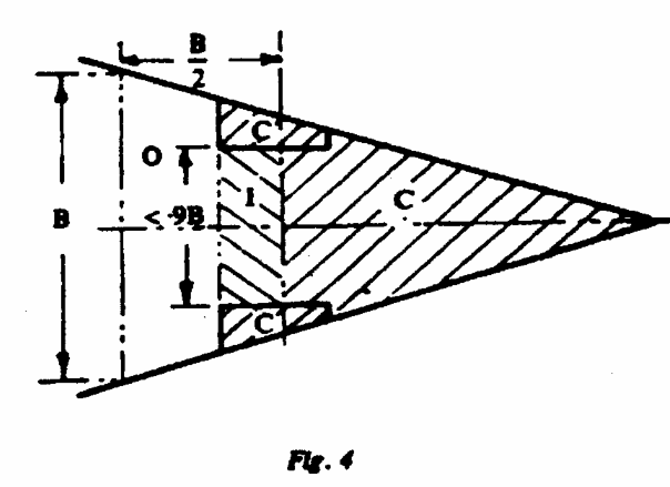
A space shall be considered an ‘Excluded space’ in the following cases:
A space within an erection opposite to an end opening extending from deck to deck.
A space under an overhead deck covering, open to the sea and weather, with no other connection to the ship side other than stanchions.
A space in a side-to-side erection directly in way of opposite side openings.
A space in erection immediately below an uncovered opening in the deck overhead, which is exposed to weather.
A recess in the boundary bulkhead of an erection which is exposed to the weather and the opening of which extends from deck to deck without means of closing.
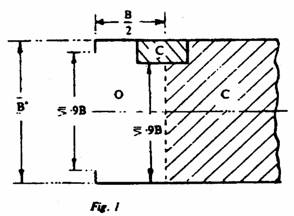
Excluded Space – Tonnage Convention Fig.1
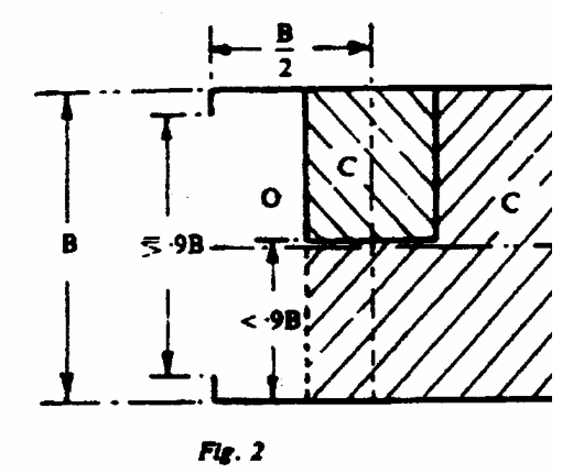
Excluded Space – Tonnage Convention Fig.2
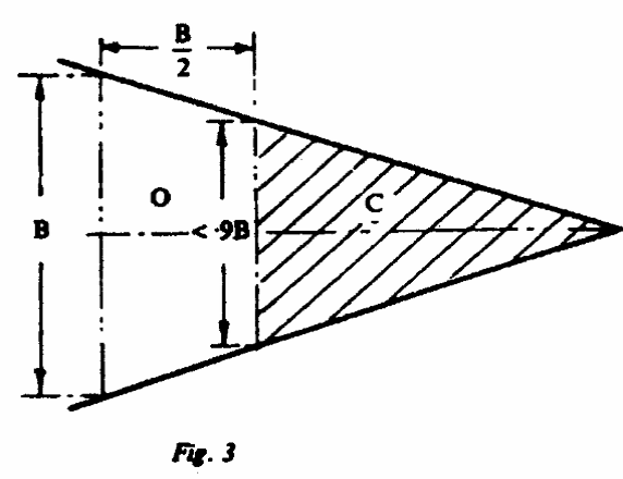
Excluded Space – Tonnage Convention Fig.3
Excluded Space – Tonnage Convention Fig.4
O = Excluded Space,
C = Enclosed Space,
I = space to be considered as an enclosed space.
B = breadth of the deck in way of the opening.
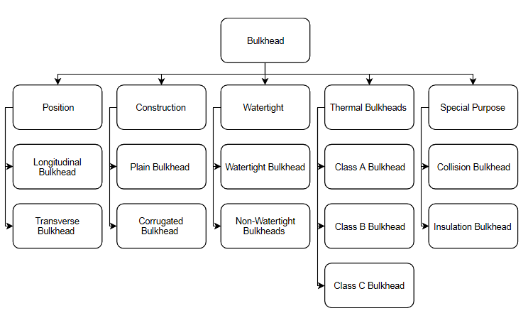
Bulkheads:- Vertical partitions on a ship are called bulkheads.
Types of Bulkhead as per Orientation:
Longitudinal: Placed in
longitudinal direction on a ship.
Transverse: placed in Transverse
direction on a ship.
Types of Bulkheads as per construction:
Watertight bulkheads: These bulkheads are water tight and prevent flooding. Numbers of Watertight bulkheads: 1- Collision bulkhead, 1- aft peak bulkhead, 1- Bulkhead of engine room and 1- bulkhead aft of engine room. Aft peak bulkhead and bulkhead aft of engine room may be combined into the additional bulkheads are to be provided as per rules depending upon the length of the ship & requirements.
Non-watertight bulkheads:
Are screens in accommodation and do not contribute to strength or water tightness.
Used to subdivide compartment into smaller units of accommodation of stores Non-watertight Bulkheads.
Factors to be taken in to account during cargo planning stage in order to minimize the damage to watertight transverse bulkheads and tank tops in bulk carriers having combination cargo/ ballast holds.
The common damage/defects that may occur on watertight transverse bulkheads situated at the ends of dry cargo holds of a bulk carrier:-
Fractures that may occur in the deck plating at hatches and in connected comings.
Causes of cracking in way of no. 1 cargo hold.
The damages caused by cargoes in cargo holds, especially to tanktop plating and side:
At loading and unloading ports for coal or iron ore, large grab buckets, high-capacity cargo.
Loaders, bulldozers and pneumatic hammers may be employed for cargo-handling operations.
Large grab buckets may cause considerable damage to tank top plating when being dropped to grab cargo.
Use of bulldozers and pneumatic hammers may also be harmful to cargo hold structures and may result in damage to tank tops, bilge hoppers, hold frames and end brackets.
Lumber cargoes may also cause damage to the cargo hold structures of smaller bulkers that are employed in the carriage of light bulk cargoes and lumbers.
Cracking on large bulk carriers, Ballast tanks. Ability to interpret given figures for bending moments and shear forces.
A standard fire test is a test in which specimens of the relevant bulkhead or decks are exposed in a test furnace to temperatures corresponding approximately to the standard time-temperature curve in accordance with the test method specified in the FTP Code.
The specimen must have an exposed surface of 2.44m width and 2.5m height. In case of decks and ceilings, they must be of 2.44mm width and 3.04m length. When the maximum overall height in practice is to be less than that given above, then the test specimen shall be of the maximum height to be used in practice.
Orientation of the test piece shall be maintained. A bulkhead shall be tested vertically and a deck or ceiling shall be tested horizontally.
Class A and B Class bulkheads and doors shall be tested from each side.
A-Class un-insulated steel bulkheads and decks without openings shall be treated as A-0 and no test is required. All other divisions, including class “A-0” divisions with a structural core of aluminum, are required to be tested.
Constructions shall be tested without paint or other superimposed finishes,subject to the approval of the Administration.
The specimen being tested should resemble as closely as possible the intended construction and include atleast one joint, where applicable.
Temperature thermocouples are placed at various points on the specimen to be tested as per FTP Code. During the test, temperatures are recorded at intervals not exceeding 1 minute.
The average temperature of the furnace as derived from the furnace thermocouples shall be monitored and controlled such that it follows the standard time-temperature curve. (This is a smooth curve drawn using furnace temperature points measured at 5m, 10m, 15m, 30m and 60m starting from the initial furnace temperature.)
The average temperature rise on the unexposed surface shall be calculated as the average of the rises recorded by the individual thermocouples to check if the specimen complies with the requirement on temperature rise.
If there is any flaming seen on the unexposed side, the duration and the location shall be recorded. In cases where it is difficult to identify whether or not there are flames then the cotton-wool pad shall be applied to see if ignition of the pad can be initiated.
For all “A” class divisions, including those with doors, the test shall continue for a minimum of 60 min. For all “B” class divisions, including those with doors, the test shall continue for a minimum of 30 min.
Limitations in the use of oils as fuel:
The following limitations shall apply to the use of oil as fuel:
Except as otherwise permitted by this paragraph, no oil fuel with a flashpoint of less than 60°C shall be used.
In emergency generators oil fuel with a flashpoint of not less than 43°C may be used.
The use of oil fuel having a flashpoint of less than 60°C but not less than 43°C may be permitted (e.g., for “feeding the emergency fire pump” s engines and the auxiliary machines which are not located in the machinery spaces of category A) subject to the following:
Fuel oil tanks except those arranged in double bottom compartments shall be located outside of machinery spaces of category A.
Provisions for the measurement of oil temperature are provided on the suction pipe of the oil fuel pump.
Stop valves and/or cocks are provided on the inlet side and outlet side of the oil fuel strainers.
Pipe joints of welded construction or of circular cone type or spherical type union joint are applied as much as possible.
In cargo ships the use of fuel having a lower flashpoint than otherwise specified, for example crude oil, may be permitted provided that such fuel is not stored in any machinery space and subject to the approval by the Administration of the complete installation.
Non Combustible material:
It is the one which neither burns nor gives off flammable vapours in sufficient quantity for self-ignition when heated to approximately 7500C, as indicated in the FTP Code.
A & B class divisions shall be constructed of non-combustible materials with the following exceptions:
Adhesives and vapour barriers, but they should have low flame spread characteristics.
Sealing materials used in penetration systems.
Seal for gas/weather/water tight doors.
Special category Spaces:
Special category spaces are
those enclosed vehicle spaces above and below the bulkhead deck, into and from
which vehicles can be driven and to which passengers have access. Special
category spaces may be accommodated on more than one deck provided that the
total overall clear height for vehicles does not exceed 10 m.
In passenger ships carrying
more than 36 passengers, the bulkheads and decks of special category spaces
shall be insulated to’A-60″ class standard.
In passenger ships, indicators
shall be provided on the navigation bridge to indicate when any fire door
leading to or from the special category spaces is closed.
In special category spaces
to which any passengers carried can have access, the number and locations of
the means of escape shall be to the satisfaction of the Administration.
Walkways to the means of escape must be provided with a breadth of at least 600
mm. The parking arrangements for vehicles shall maintain the walkways clear at
all times.
The ventilation system for
special category spaces must be sufficient to provide 10 air changes per hour.
An efficient fire patrol
system shall be maintained in special category spaces. If an efficient fire
patrol system is maintained by a continuous fire watch at all times during the
voyage, a fixed fire detection and fire alarm system is not required.
Special category spaces
shall be fitted with a fixed water-based fire-fighting system with provision of
manual operation, which shall protect all parts of any deck and vehicle platform
of such spaces. A sufficient number of drainage valves must be provided to
ensure complete drainage of the system. Also, means shall be provided to
prevent the blockage of drainage arrangements.
There are additional
requirements for special category spaces of Ro-Ro Passenger ships. For example,
CCTV surveillance and a water leakage detection system is required to be fitted
to provide an indication to the navigation bridge and to ECR of any leakage
through the bow or stern doors which could lead to flooding of special category
spaces or ro-ro spaces.
Q) Write short notes on Torsional Stress on ships.
Ans:- Torsional Stress on ships:
When a body is subject to a
twisting moment which is commonly referred to as torque, that body is said to
be in ‘torsion’. A ship heading obliquely (45°) to a wave will be subjected to
righting moments of opposite direction at its ends twisting the hull and
putting it in ‘torsion’.
In most ships, these
torsional moments and stresses are negligible but in ships with extremely wide
and long deck openings they are significant. A particular example is the larger
container ship where at the topsides a heavy torsion box girder structure
including the upper deck is provided to accommodate the torsional stresses.
Torsional stresses also
occur due to unsymmetrical loading along the centre line of the vessel. (For
example, too much load on the fwd-port side and at the aft-stbd side)
Q) What are the Intact
Stability requirements of Oil Tanker Ships
Ans:- Intact Stability requirements of Oil Tanker Ships: Oil
tankers, as defined in the section Definitions, shall comply with regulation 27
(Intact Stability) of Annex I to MARPOL 73/78:-
Every oil tanker of 5,000 tonnes deadweight and above delivered on or after 1 February 2002, as defined in regulation 1.28.7, shall comply with the intact stability criteria specified in paragraphs 1.1 and 1.2 of this regulation, as appropriate, for any operating draught under the worst possible conditions of cargo and ballast loading, consistent with good operational practice, including intermediate stages of liquid transfer operations. Under all conditions the ballast tanks shall be assumed slack.
In port, the initial metacentric height GMo, corrected for the free surface measured at 0° heel, shall be not less than 0.15 m.
At sea, the following criteria shall be applicable:
the area under the righting lever curve (GZ curve) shall be not less than 0.055 m·rad up to θ = 30° angle of heel and not less than 0.09 m·rad up to θ = 40° or other angle of flooding θf* if this angle is less than 40°. Additionally, the area under the righting lever curve (GZ curve) between the angles of heel of 308 and 40° or between 30° and θf, if this angle is less than 40°, shall be not less than 0.03 m·rad;
the righting lever GZ shall be at least 0.20 m at an angle of heel equal to or greater than 30°;
the maximum righting arm shall occur at an angle of heel preferably exceeding 30° but not less than 25°; and
the initial metacentric height GMo, corrected for free surface measured at 0° heel, shall be not less than 0.15 m.
The requirements of paragraph 1 of this regulation shall be met through design measures. For combination carriers simple supplementary operational procedures may be allowed.
Simple supplementary operational procedures for liquid transfer operations referred to in paragraph 2 of this regulation shall mean written procedures made available to the master which:
are approved by the Administration.
Indicate those cargo and ballast tanks which may, under any specific condition of liquid transfer and possible range of cargo densities, be slack and still allow the stability criteria to be met. The slack tanks may vary during the liquid transfer operations and be of any combination provided they satisfy the criteria;
will be readily understandable to the officer-in-charge of liquid transfer operations;
provide for planned sequences of cargo/ballast transfer operations;
allow comparisons of attained and required stability using stability performance criteria in graphical or tabular form;
require no extensive mathematical calculations by the officer-incharge;
provide for corrective actions to be taken by the officer-incharge in case of departure from recommended values and in case of emergency situations; and
are prominently displayed in the approved trim and stability booklet and at the cargo/ballast transfer control station and in any computer software by which stability calculations are performed.
Q) Describe the precautions to be taken while carrying out inclining test.
Ans:- Precautions to be taken while carrying out Inclining Test:
The ship must be moored in quiet sheltered waters free from the effects of passing vessels.
There must be adequate depth of water under the keel so that the bottom of the ship does not touch the sea bed on inclination.
There should little or no wind. If there is any wind the ship should be head on or stern to it.
The ship should be floating free. There should be no barges alongside.
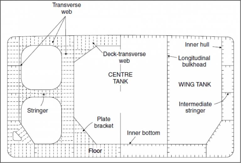
Q) Sketch and Label Mid-Ship Section of a Double Hull Oil Tanker.
Midship Section of a Double Hull Tanker
The above figure is the
midship section of a double hull tanker. The right half of the drawing shows an
ordinary frame, where the outer and inner hull plates are longitudinally
framed. The centre tank is used for storage of cargo oil, and the wing tanks or
segregated ballast tanks (SBTs) are used for carrying sea water ballast. The
SBTs are epoxy coated so as to prevent corrosion. Do observe that the
longitudinal stiffeners on the wing tank longitudinal bulkhead are placed
towards the wing tank, and not the centre cargo oil tank. Why? In order to
prevent oil accumulation on them. The double bottom spaces are also used for
water ballast, and the stiffeners on the inner bottom plating are always
towards the double bottom space.
A deep transverse web frame
(left half of the above figure) is given at every three to four frame spaces in
order to provide transverse strength to the ship. The longitudinal stiffeners
are welded to these web frames. Stringers are provided on these transverse webs
to provide further strengthening.
Today, irrespective of the
classification society certifying the design of a tanker, the structural design
of double hull tankers is done according to The Harmonised Common Structural
Rules (CSR) for Tankers, by IACS.