Q) For a fully automatic provisions refrigeration system incorporating a number of rooms: Sketch a line diagram detailing the devices incorporated into the refrigeration system to protect the machinery and equipment against malfunction.
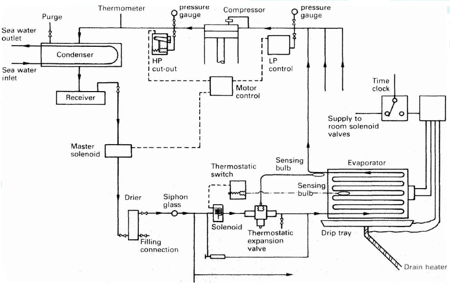
Main Components of Refrigeration plants:- Any refrigeration unit works with different components inline to each other in series. The main components are:
- Compressor: Reciprocating single or two stage compressor is commonly used for compressing and supplying the refrigerant to the system.
- Condenser: Shell and tube type condenser is used to cool down the refrigerant in the system.
- Receiver: The cooled refrigerant is supplied to the receiver, which is also used to drain out the refrigerant from the system for maintenance purpose.
- Drier: The drier connected in the system consists of silica gel to remove any moisture from the refrigerant.
- Solenoids: Different solenoid valves are used to control the flow of refrigerant into the hold or room. Master solenoid is provided in the main line and other solenoid is present in all individual cargo hold or rooms.
- Expansion valve: An Expansion valve regulates the refrigerants to maintain the correct hold or room temperature.
- Evaporator unit: The evaporator unit acts as a heat exchanger to cool down the hold or room area by transferring heat to the refrigerant.
- Control unit: The control unit consist of different safety and operating circuits for safe operation of the refer plant.
Compressor safety devices: The compressor is protected by three safety switches:-
- The OP switch or Oil Differential Pressure switch compares the measured lubricating oil pressure to the Suction (crankcase) pressure. Should the differential pressure fall below a pre-set minimum (about 1.2 bar) then the compressor will trip and require a manual reset to restart. A time delay is built into the circuit to allow sufficient time for the lubricating oil pressure to build up when starting before arming the circuit.
- The HP or High Pressure switch, is fitted to the outlet of the compressor before the isolating valve. On over pressurization (dependent on the refrigerant, up to about 24bar bar for R22) the switch will trip the compressor and a manual reset is required before restart.
- The LP or Low Pressure switch when activated (at about 1 bar for R22) will trip the compressor and require a manual reset before the compressor can be restarted.
- This normally takes the form of an LP cut out pressure switch with automatic reset on pressure rise. The cut out set point is just above the LP trip point says at about 1.4bar.
- An adjustable differential is set to about 1.4bar to give a cut in pressure of around 2.8 bar. The electrical circuit is so arranged that even when the switch has reset, if no room solenoid valves are open the compressor will not start. This is to prevent the compressor cycling due to a leaky solenoid valve.
- In addition to this extra LP switches may be fitted which operate between the extremes of the LP cut in and cut out to operate compressor unloaders.
- Some modern systems contain a rotary vane compressor with variable speed (frequency changing) control.
Q) For a fully automatic provisions refrigeration system incorporating a number of rooms: Explain how critical temperature restricts plant operation and how these limitations overcome?
Ans:- The Critical Point:- The critical point is the point above which:
- The gas will not liquefy by the action of pressure alone. This is an important temperature for refrigeration systems which rely on the change of state for heat transfer.
- The gas will not liquefy by cooling alone.
Working of Ship’s Refrigeration Plant:-
- The compressor acting as a circulation pump for refrigerant has two safety cut-outs- Low pressure (LP) and High Pressure (HP) cut outs.
- When the pressure on the suction side drops below the set valve, the control unit stops the compressor and when the pressure on the discharge side shoots up, the compressor trips.
- LP or low pressure cut out is controlled automatically i.e. when the suction pressure drops, the compressor stops and when the suction pressure rises again, the control system starts the compressor. HP or high pressure cut out is provided with manually re-set.
- The hot compressed liquid is passed to a receiver through a condenser to cool it down. The receiver can be used to collect the refrigerant when any major repair work has to be performed.
- The master solenoid is fitted after the receiver, which is controlled by the control unit. In case of sudden stoppage of compressor, the master solenoid also closes, avoiding the flooding of evaporator with refrigerant liquid.
- The room or hold solenoid and thermostatic valve regulate the flow of the refrigerant in to the room to maintain the temperature of the room.
- For this, the expansion valve is controlled by a diaphragm movement due to the pressure variation which is operated by the bulb sensor filled with expandable fluid fitted at the evaporator outlet.
- The thermostatic expansion valve supplies the correct amount of refrigerants to evaporators where the refrigerants takes up the heat from the room and boils off into vapours resulting in temperature drop for that room.
- This is how temperature is maintained in the refrigeration plant of the ship.
- A safety system includes alarm, cut offs, and trips which safeguards the machinery and its parts from getting damage.
Q) For a fully automatic provisions refrigeration system incorporating a number of rooms: What is the effect on the environment of the release of refrigerants into the atmosphere?
Ans:- Environmental and Safety properties of Refrigerants:- At present the environment friendliness of the refrigerant is a major factor in deciding the usefulness of a particular refrigerant. The important environmental and safety properties are:
- Ozone Depletion Potential (ODP): According to the Montreal protocol, the ODP of refrigerants should be zero, i.e., they should be non-ozone depleting substances.
- Global Warming Potential (GWP): Refrigerants should have as low a GWP value as possible to minimize the problem of global warming. Refrigerants with zero ODP but a high value of GWP (e.g. R134a) are likely to be regulated in future.
- Total Equivalent Warming Index (TEWI): The factor TEWI considers both direct (due to release into atmosphere) and indirect (through energy consumption) contributions of refrigerants to global warming. Naturally, refrigerants with as a low a value of TEWI are preferable from global warming point of view.
- Toxicity: Ideally, refrigerants used in a refrigeration system should be non-toxic. Toxicity is a relative term, which becomes meaningful only when the degree of concentration and time of exposure required to produce harmful effects are specified. In general the degree of hazard depends on:
- Amount of refrigerant used vs total space
- Type of occupancy
- Presence of open flames
- Odor of refrigerant, and
- Maintenance condition
- Flammability: The refrigerants should preferably be nonflammable and non-explosive. For flammable refrigerants special precautions should be taken to avoid accidents.
- Chemical stability: The refrigerants should be chemically stable as long as they are inside the refrigeration system.
- Compatibility with common materials of construction (both metals and non-metals)
- Miscibility with lubricating oils: Oil separators have to be used if the refrigerant is not miscible with lubricating oil (e.g. ammonia). Refrigerants that are completely miscible with oils are easier to handle (R12).