Actions to be taken while Observing damage cargo during discharging operation on board Car Carrier ships:
- Stop discharge, take as many photo as possible from different angle showing the damage.
- Inform Master. Describe how the damage took place.
- Take the sign of the foreman on the stevedore damage form.
- Take printouts of the photo and attach it to the stevedore damage form.
- If stevedore not signing the damage report form raise LOP. Inform central planner in containers. (Safeguard the owner’s interest.)
General Precautions to be observed while working Ro-Ro include:
- Preventing unauthorised entry of vehicles and pedestrians into the terminal.
- Enforcement of speed limits.
- Segregation of vehicles and pedestrians.
- Adequate marshaling of passenger carrying vehicles.
- Provision of safe routes from car decks to passenger accommodation.
- Maintain clear approach to Ro-Ro ramp.
- Only those involved in loading/ unloading allowed onto ramp.
- If pedestrian access must be via the ramp, provide safe means of access e.g. raised walkway.
- Ramp kept clear of obstacles.
- Good co-ordination between ship/shore to maintain ramp at safe level/gradient.
- Clear rules controlling movement of vehicles on/off the ship.
- Procedures for abnormal loads
- Lashing Teams:-
- Wear Protective clothing.
- Work in teams or in sight of each other.
- Stand where visible to loading vehicles.
- Use whistle stop and clear, standardised hand signals
- Trained and competent in lashing procedures.
- Clear safety procedures for using ships cargo lifts.
- Safe systems of work for Sto-Ro especially regarding safe use of large lift trucks.
- Control Vehicle fume:
- Ensure ships fans running before loading / unloading begins.
- Minimise number of engines running at one time.
- Maintain company controlled vehicles in accordance with manufacturers guidelines.
Pre-loading precautions for Loading Cars on a Car Carrier:
- Preventing unauthorized entry of vehicles and pedestrians into the terminal.
- Enforcement of speed limits.
- Segregation of vehicles and pedestrians.
- Adequate marshalling of passenger carrying vehicles.
- Provisions of safe route from car decks to passenger accommodation.
- Maintain clear approach to Ro-Ro ramp.
- Only those involved in loading/ unloading allowed onto ramp.
- If pedestrian access must be via the ramp, provide safe means of access e.g. raised walkway.
- Ramp kept clear of obstacles.
- Good co-ordination between ship/shore to maintain ramp at safe level/ gradient.
- Clear rules controlling movement of vehicles on/off the ship.
- Procedures for abnormal loads.
- Lashing teams
- Wear protective clothing.
- Work in team or in sight of each other
- Stand where visible to loading vehicles
- Use whistle stop and clear, standardized hand signals
- Trained and competent in lashing procedures.
- Clear safety procedures for using ships cargo lifts.
- Safe systems of work for Sto-Ro especially regarding safe use of large lift trucks.
- Control vehicle fume
- Ensure ships fans are running before loading/ unloading begins.
- Minimize number of engines running at one time.
- Maintain company controlled vehicles in accordance with manufacturer’s guidelines.
Safe method of stowage of heavy cargo items such as locomotives and project cargo being brought by your ship during monsoon:
“ANNEX 5 of CSS code – Safe stowage and securing of heavy cargo items such as locomotives, transformers, etc.”
Following are guidelines wrt lashing of heavy cargoes:
Securing Against Sliding and Tipping:
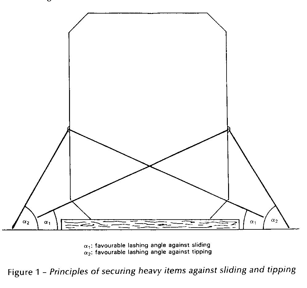
- Whenever possible, timber should be used between the stowage surface and the bottom of the unit in order to increase friction. This does not apply to items on wooden cradles or on rubber tyres or with similar bottom material having a high coefficient of friction.
- The securing devices should be arranged in a way to withstand transverse and longitudinal forces which may give rise to sliding or tipping.
- The optimum lashing angle against sliding is about 25°, while the optimum lashing angle against tipping is generally found between 45° and 60° (fig 1).
- If a heavy cargo item has been dragged into position on greased skid boards or other means to reduce friction, the number of lashings used to prevent sliding should be increased accordingly.
- If, owing to circumstances, lashings can be set at large angles only, sliding must be prevented by timber shoring, welded fittings or other appropriate means. Any welding should be carried out in accordance with accepted hot work procedures.
Securing Against Heavy Seas on Deck:-
- Whilst it is recognised that securing cargo items against heavy seas on deck is difficult, all efforts should be made to secure such items and their supports to withstand such impact and special means of securing may have to be considered.
Heavy Cargo Items Projecting over the Ship’s Side:-
- Items projecting over the ship’s side should be additionally secured by lashings acting in longitudinal and vertical directions.
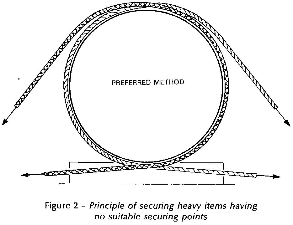
Attachment of Lashings to Heavy Cargo Items:-
- If lashings are to be attached to securing points on the item, these securing points should be of adequate strength and clearly marked. It should be borne in mind that securing points designed for road or rail transport may not be suitable for securing the items on board ship.
- Lashings attached to items without securing points should pass around the item, or a rigid part thereof, and both ends of the lashing should be secured to the same side of the unit (figure 2).
- Securing devices should be assembled so that each component is of equal strength.
- Particular attention should be paid to the correct use of wire, grips and clips. The saddle portion of the clip should be applied to the live load segment and the U-bolt to the dead or shortened end segment.
Mixed securing arrangements of devices with different strength and elongation characteristics should be avoided.
Planning & Preparations to be done before Loading and Unloading of Vehicles on a Car Carrier:
Stowage:
- Shipper’s special advice or guidelines regarding handling and stowage of individual vehicles should be observed.
- Vehicles should as far as it is possible, be aligned in a fore and aft direction. Athwartship stowage should only be allowed with the express permission of the Master having taken into account the anticipated weather for the intended voyage and provided that adequate securing arrangements can be made.
- Vehicles should not be stowed across water spray fire curtains or flood barrier doors where fitted.
- Vehicles should be closely stowed athwartships so that, in the event of any failure in the securing arrangements or from any other cause, the transverse movement is restricted. However, sufficient distance should be provided between vehicles to permit safe access for the crew and for passengers getting into and out of vehicles and going to and from accesses serving vehicle spaces.
- Safe means of access to securing arrangements, safety equipment, and operational controls should be provided and properly maintained. Stairways and escape routes from spaces below the vehicles decks should be kept clear.
- Vehicles should not obstruct the operating controls of bow and stern doors, entrances to accommodation spaces, ladders, stairways, companionways, escapes, access hatches, firefighting equipment, controls to deck scupper valves and controls to fire dampers in ventilation trunk.
- Parking brakes, where provided, of each element of a combination of vehicles should be applied.
- Semi-trailers should not be supported on their landing legs during sea transport unless the landing legs are specially designed for that purpose and so marked.
- Semi-trailers should not be supported on their landing legs during sea transportation unless the deck plating has adequate strength for the point loadings, or there are suitable arrangements to spread the load.
- Uncoupled semi-trailers should be supported by trestles or similar devices placed in the immediate area of the drawplates so that the connection of the fifth-wheel to the kingpin is not restricted. Such trestles or devices should be tested and clearly marked to show their maximum permitted load which must not be exceeded.
- Depending on the area of operation, the predominant weather conditions and the characteristics of the ship, freight vehicles should be stowed so that the chasses are kept as static as possible by not allowing free play in the suspension. This can be done by securing the vehicle to the deck as tightly as the lashing tensioning device will permit or by jacking up the freight vehicle chasses prior to securing.
- Depending on the area of operation, the predominant weather conditions and the characteristics of the ship, freight vehicles should be stowed so that the chassis are kept as static as possible by not allowing free play in the suspension. This can be done by securing the vehicle to the deck as tightly as the lashing tensioning device will permit or by jacking up the freight vehicle chassis prior to securing. Since compressed air suspension systems may lose air, adequate arrangements should be made to prevent the slackening off of lashings as a result of air leakage during the voyage. Such arrangements may include the jacking up of the vehicle or the release of air from the suspension system where this facility is provided.
Securing:
- Securing operations should be completed before the ship leaves the berth.
- Persons appointed to carry out the task of securing vehicles should be trained in the use of the equipment to be used and in the most effective methods for securing different types of vehicles.
- Persons supervising the securing of vehicles should be conversant with the contents of the “Cargo Securing Manual”.
- There should be an adequate supply of cargo securing gear which is maintained in a sound working condition.
- Freight vehicles of more than 3.5 tonnes should be secured in all circumstances where the expected conditions for the intended voyage are such that movement of the vehicles relative to the ship could be expected. So far as is reasonably practicable the securing arrangements should be adequate to ensure that there will be no movement from any cause which will endanger the ship.
- When freight vehicles are being stowed on an inclined deck, the wheels should be chocked before lashing commences. During discharge, sufficient restraints should remain in place until the tractor unit has been connected, where appropriate.
- Lashings should not be attached to or led across lamp brackets, trailer landing legs, kingpins, sideguards or bumpers except those specially designed for this purpose.
- When wheel chocks are used to restrain a semi-trailer they should remain in place until the semi-trailer is properly secured to the semi-trailer towing vehicle.
- To avoid being damaged during loading and unloading all securing equipment should be kept clear of moving vehicles on the vehicle deck.
- Inspection routines for securing equipment should be specified in the Cargo Securing Manual and require at least one inspection every six months by a trained person. Defective equipment should be taken out of service and placed where it cannot be used inadvertently.
Lashing Arrangements:
- Lashings should have strength and elongation characteristics appropriate for the mass of vehicle being secured.
- Steel chains are commonly used for lashing freight vehicles of more than 3.5 tonnes gross vehicle mass (GVM). Webbing straps or other novel securing systems may be used instead of steel chain, provided that they have an equivalent strength and suitable elongation characteristics (see IMO MSC/Circ 812 for further details).
- Chains/straps and associated elements (eg Hooks, shackles, elephant’s feet and tensioning devices) should have an MSL of 100 kN.
- Where, exceptionally, wire ropes or other materials are used their breaking load should be atleast 200 kN.
- Hooks and other devices which are used for attaching a lashing to a securing point should be designed and applied in a manner which prevents them from disengaging from the aperture of the securing point if the lashing slackens during a voyage.
- Lashings should be so designed and attached that, provided that there is safe access, it is possible to tighten them if they become slack.
- Securing points provided on vehicles should only be used for lashing the vehicle to the ship. Only one lashing should be attached to any one aperture loop or lashing ring at each securing point.
- The lashings are most effective on a vehicle when they make an angle with the deck of between 30 and 6 degrees. When these optimum angles cannot be achieved, additional lashings may be required.
- Where practicable, the arrangement of lashings on both sides of a vehicle should be the same, and angled to provide some fore and aft restraint with an equal number pulling forward as are pulling aft.
- Crossed lashings should, where practicable, not be used for securing freight vehicles because this disposition provides no restraint against tipping over at moderate angles of roll of the ship. With these vehicles, lashings should pass from a securing point on the vehicle to a deck securing point adjacent to the same side of the vehicle. Where there is a concern about the possibility of low coefficients of friction on vehicles such as solid wheeled trailers, additional cross lashings may be used to restrain sliding.
- Bearing in mind the characteristics of the ship, the approved “Cargo Securing Manual” and the conditions expected on the intended voyage, the master should decide on the number of lashings, if any to be used on each class of vehicle having regard to any vehicles which by the nature or disposition of their load may require particular attention.
-
 Cargo Solved MMD Past Papers Phase 1 Chief MatePrice range: ₹ 244.00 through ₹ 576.00
 -
 2nd Mate (F.G.) & NCV (NWKO) – Volume 3 (Cargo)₹ 219.00
 -
 Cargo Consolidated Notes for Phase 1 Chief Mate₹ 361.00
Problem areas in Ro-Ro ships:
Enclosed spaces are a fundamental component to the ship’s structure and are also circuitously critical for the economics of running the shipping company. A large part of the ship’s earnings in the form of cargo (dry as well as wet) is exhumed from large void spaces commonly known as ‘tanks’, within the ships configuration. As a matter of fact, the steel tanks aid with the ship’s stability, especially when stability is associated to juggling between filling and discharge of fuel oil or water as ballast / domestic.
Considering the immense significance of these spaces, they have to be regularly maintained. Planned inspections and regular cleaning / repairs would be best for ascertaining top shape of the ship’s hull and its components.
However, it is proven that over time the ships’ steel deteriorates structurally, and if left unchecked, can worsen to serious framing and compositional defects with sometimes causing loss to ship, even lives. Consequently, in order to avoid such premature loss to life or for that matter loss of revenue from forced off-hire periods, effective repairs are indispensable; this includes visibly examining the tanks methodically.
The intention of this study is to present a generic guide of how to go about inspecting the ships tanks namely, cargo holds / tanks (dry and wet), ballast tanks, void spaces, fuel oil tanks, fresh water storage tanks, etc.
Let’s first quickly run down through the general defects that affect the steel structures due to direct wear and tear.
1. Corrosion – Also considered as ‘material wastage’, it is the lead cause for structural deformations and fracturing. It is by far the most ‘popular’ of all other defects directly related to steel and its components. If left unattended, corrosion is a disaster waiting to happen; either by cargo or fuel oil contamination, structural losses, pollution and finally possible loss of the ship itself.
2. Deformation – It is a sub-component defect caused due to damage of steel platings or material failure. It could be a change in shape or physical disfigurement of steel that is caused either by implosion (caused due to vacuum build up in tanks) or explosion, excessive dynamic (wave bending / loading) as well as static stress (ship’s hogging and sagging conditions)and strains onto the steel structures, and likewise. It should be noted that deformations observed on the ship’s hull are more likely to affect structures on the interior too.
3. Fractures – This is due to propagation of cracks through the steel plating, which have been left unattended, obviously. Most of it occurs due to excessive stress concentrated on weakened steel plates throughout the tanks’ dimensions. There have been many cases where inspectors have arrested ships, especially bulk carriers, where imminent cracks (mainly due to concentration of stress) through the cargo areas have been observed. Welding defects have also been observed to be the cause of fractures.
As we are aware that entering the tank or the enclosed spaces onboard encompasses certain mandatory procedures, which should be followed in particular. Prerequisites such as Permit to Work in Enclosed Spaces, PPE, high beam lighting, oxygen / gas detection meters, communications, etc. are mandatory while undertaking such critical operations. Once all the essentials are in place, a competent officer should head the inspection process after chalking out the tasks that are required to be ticked off, say for completing a PMS. Needless to say, onboard checklists provide a complete synopsis as to what one has to confirm while inspecting the tanks.
Here are a few pointers one should specifically identify while inspecting the steel tanks:-
1. Assessing the overall condition – Immediately on entering the enclosed space one can figure out the tank’s well being by considering the state of the access ways and the ladders, paint coatings, and by closely observing areas susceptible to corrosion such as near the weld joints. Rungs, step ways and ladders are often the foremost members that are exposed to deterioration due to oxidation. The competent officer should examine the material wastage throughout the set of access ways and related components. An overall study of the paint coating would permit the competent person to estimate how the tank has reacted to general corrosion. For easy identification of loop holes, the paint applied on the surface is generally light in colour. Thereby, re-coated areas can be easily spotted, should be re-checked for coating failure or for scaling or pitting in the vicinity.
2. Condition of corrosion levels – General corrosion appears to be as a non-protected oxidation that tends to crop up homogeneously on internal surfaces of the holds or tanks which have been left uncoated. The corroded scale frequently breaks off, revealing the bare metal, which is susceptible to corrosive attack. In tanks and holds that have been coated, corrosion starts affecting the moment the coating starts breaking down. Determining thickness reduction in the steel plates is difficult unless excessive shrinking has occurred.
For example, corrosion on the inner surfaces of the liquid cargo tanks (example, Crude Oil Tankers) is mainly due to the mixture of corrosive gases, crude oil acids, as well as sea water (Crude oil washing). This along with the fluctuations in temperatures within the tanks and structural flexing, over a period of time, shrinks the thickness of the steel plating and associated supports, ultimately leading to failure of the steel structure.
Careful examination should be carried out in areas such as – in the vicinity of sounding pipes and striker plates, openings for the air vents and tank gauging, internal piping including expansion joints, dresser coupling and related fittings / joints / clamps, near the operational valves within the tanks, bilges and tank top areas, underside of hatch coamings / tank openings, bulkheads in general, joints associated with girders, web frames, etc.
3. Condition of ‘sacrificial’ anodes fitted inside the tank – Normally such anodes are made up of zinc among other elements and provide excellent preventive measures to fight corrosion within the tanks, especially the ballast tanks. Due to their sacrificial nature, the anodes, over a period of time get ‘wasted’. Hence, in order to maintain their integrity, anodes have to be checked and inspected closely for excessive wear and tear. A record of material wastage should be maintained for future examining. One must also inspect whether the anodes are well secured to the brackets provided.
4. Checking for Damages / Cracks / Deformations – Adequate lighting in the tanks is necessary for the inspection work and for identifying deformations or surface dents. Shadows are one of the best indicators to highlight any buckling or cracks within the tanks. However this may not be the case for darker paint coatings (Coal Tar Epoxy, for example) where the tanks have to be lit up to the max in order to locate the defects. Deformations may generally not be readily obvious when viewed over a larger area. To identify this, it is good idea to highlight the area using a high beam torch by projecting it parallel to the surface. Where it is difficult to identify defects in a straight line by the torch, the old school method of using a length of string or rope could be considered for determining the obscured deformations on the surfaces.
Buckling is another condition of large deformations which can be caused due to a diminutive increase in loads. Permanent buckling may arise due to overloading weak structures (read – corrosion or contact damage)
5. Pitting corrosion and blister formation – Pitting Corrosion is often known to be observed in the bottom plating of ballast tanks especially near the ‘bell-mouth’, near the ‘bell-mouth’ in a liquid cargo tank, or next to suction wells associated with the submerged pumps fitted within the tanks. Pitting Corrosion begins mostly with the local breakdown of the coatings, exposing the bare metal, and thereby getting accentuated by oxidation and galvanic reactions in the area.
Blister formation is a common site in areas where the surface preparation is inadequate prior to application of paint coats or for some reason the coating failed to adhere to the surface. The officer must be on a look out for these unwary bumps on the tank surfaces that may act as alibi to the mounting decay underneath.
6. Condition of the tank gauging systems – Gauging systems that include gas measuring gauges, pressure gauges, temperature gauges, remote level sensing meters, sounding pipes as well as the striker plates should be checked for operational abnormalities. Rusting, too, is often found underneath the tank top near the conduits that encompass the gauges. If possible, it is always a good idea to try and clear out debris (example – mud, oil deposits) manually from the remote measuring sensors and attempt operating them. For example, during the inspection process physically testing the ‘remote’ gas measuring devices may be well worth the assessment.
The gauges fitted inside or outside the tank must be calibrated during major inspection (dry dock) or at intervals defined by the maker.
7. Condition of the Safety Devices – Safety devices fitted in the tanks are critical for providing the operators a remote indication of an unwanted threat such as water ingress in the bilges of cargo holds due to sweating or any other reason for that matter. The importance of such devices onboard is high and should be regarded as priority for visible examination. It is not very frequent that the bilge high level and low level alarms of critical spaces such as in the ship’s chain locker, dry cargo holds, void spaces, etc. would be manually tested and scrutinised closely for operational deficiencies.
8. Condition of Mud or Sludge Build Up – Accumulation of mud and oily sludge in the tanks could be detrimental in terms of hiding away serious defects and also to promote development of structural deterioration underneath the horizontal / parallel surfaces. Therefore, it is highly recommended to remove the excess debris prior any tank inspection, this means washing the crude oil tanks enough in order to visibly locate the defects, or physically hosing down the mud accretion in ballast tanks. This also aids in identifying any bottom shell pitting corrosion or deformations.
9. Condition of Cargo Equipment – Cargo equipment within the tanks include heating coils, cargo pumps, crude oil washing machines, remote gauging systems, temperature / heat sensors, etc. Leak test using compressed air or steam could be carried out on heating coils whereby the pipe-work and steam traps within the tanks must be thoroughly inspected visually for faults and leaks. The competent officer should also physically ensure the optimal operation of all the cargo equipment fitted internally. This could be done by remotely trying out the system from a control room and feedback confirmed from within the tank. Any irregularity in the equipments’ operation must be recorded and later reported.
Finally, a few other areas onboard susceptible to defects and damages that must be frequently examined –
– Ballast tanks that are bordering the hot Engine Room spaces
– Ballast and void tanks neighboring the heated fuel oil and cargo tanks
– Tanks that are in the vicinity to areas where vibration levels are high
– Side shell spaces between the loaded and light draughts
– Tanks adjacent to external tug contact points
– Spaces in the forward part of the vessel, especially to be considered after heavy weather
Therefore, in order to detect and identify where a fault has occurred in the enclosed space most of the above mentioned factors would be needed to take into consideration. For evidence and record keeping, using an intrinsically safe camera or any camera with a certified explosion proof housing for that matter is highly recommended.
Need to monitor Atmosphere in Ro-Ro Spaces:-
- When internal combustion engines exhaust into a hold, intermediate deck, or any other compartment, the employer must ensure that the atmosphere is tested as frequently as needed to prevent carbon monoxide (CO) concentrations from exceeding allowable limits.
- These tests must be made in the area in which workers are working by persons competent in the use of the test equipment and procedures.
- Employers should ensure that workers control loose paper within RO-RO areas.
- Papers can be sucked into the ventilation system, blocking airflow and allowing the buildup of harmful gases.
- Employers should closely monitor air quality during all operations where overexposure may occur.
- Most modern car carriers have efficient exhaust ventilation systems. Ventilation systems in cargo holds should be started 15 minutes prior to starting work.
- The time needed may vary depending on the size of the hold and the airflow.
Vehicle Stowage and Securing (Ro-Ro Ships & Car Carrier):
IMO Resolution A. 489 (XII) – Safe Stowage and Securing of Cargo Units and other entities in Ships other than Cellular Container Ships. (Guidelines for Cargo Securing Manual).
IMO Resolution A. 533 (13) – Elements to be taken into account when considering the same stowage and securing of cargo units and vehicles on ships.
IMO Resolution A. 581 (14) – Guidelines for securing arrangements for the transport of road vehicles on ships.
IMO Resolution A. 489 (XII) – Code for safe practice of cargo stowage and securing. Annex 4 – Safe Stowage and securing of wheel-based cargoes.
A stable vehicle deck needs to be maintained, so all Ro-Ro ferries are built with stabilizers of some form. However, cargo movement can still expect to occur in very rough sea conditions even when stabilization systems are operational. To prevent movement at sea individual vehicles are secured.
- The stowage / securing of vehicles should be supervised by a responsible Ship’s Officer assisted by at least one other competent person.
- Vehicles must be loaded, stowed and secured in accord with the Cargo Securing Manual (CSM) (IMO Res. A. 489 (XII)), as approved by the authority.
- Lashing material used should have sufficient strength and should comply with the CSM.
- Securing points shall be provided on ship’s deck, spaced not more than 2.5m in the F & A direction and in the arthwartship direction not less than 2.8m and not more than 3m, same should be mentioned in the CSM of the ship.
- Minimum strength of securing point on deck should be 120kN and if more than one lashing can be attached than – no. of lashing x 120kN.
- In Ro-Ro ships the spacing and the strength may vary depending on the special consider which may be required to stow and secure road vehicles.
- Securing points on road vehicles shall be provided which shall be capable of accepting only one lasing, highlighted, provided effective restraints to the vehicle by the lashing and should be of adequate strength.
- Vehicles which are not provided with securing points should have those places clearly marked, where lashing may be applied.
- Cargo spaces in which wheel based cargo is to be stowed should be dry, clean and free from grease and oil.
- Vehicles should as far as possible be aligned F & A, with sufficient distance between vehicles so as to allow access through the vehicle deck.
- The parking brake on each vehicle/ unit should be applied and where possible the unit should be placed in ’gear’.
- Where drop loads or uncoupled units are being carried these should be landed on trestles or equivalent support, prior to being secured by chain or other suitable securing constraint.
- Road vehicles should be stowed so that the chassis are kept as static as possible, by not allowing free play in the suspension of the vehicles. By either compressing the springs by tightly securing the vehicle to the deck, by jacking up the chassis prior securing the vehicle or by releasing the air pressure on the compressed air suspension system.
- Wheels of vehicles stowed on decks should be ‘chocked’ and the hand brakes to be applied.
- Cargoes stowed on wheel based units should be adequately secured to stowage platforms or where provided with suitable means, toits sides. Any movable external components attached to a wheel based unit, such as derricks, arms should be adequately locked or secured in position.
- Suitable lashings against the incline should be secured and the unit left in an opposing gear.
- Vehicles should be lashed using the correct securing points provided on the vehicle and deck.
- All lashings applied whether of a ‘hook’ type or other variety should be secured in such a manner that in the event of them becoming slack, they are prevented from becoming detached and should also permit tensioning during the voyage when they become slack.
- All vehicle / cargo units should be secured prior to the vessel leaving the berth and such securings should be at the master’s discretion to be most effective.
- While enroute these lashings should be regularly inspected to ensure they remain effective during the time at sea.
- Personnel engaged on vehicle deck inspections should take extreme caution against injury from swaying vehicles.
- If necessary the master may alter the ship’s course while such inspections are ongoing to reduce the motion on the vehicle deck.
- Lashings should only be released once the ship is secured at the berth and personnel so engaged should take care when clearing securings which may be under tension.
Note: Lashings are considered most effective at between 30deg and 60deg to the deck line. Alternatively, additional lashings may be required.
Unit Securing – chain lashings:
Ro-Ro units are secured in accordance with the ‘Cargo Securing Manual’. In some short sea voyages, during the summer season and with a predominately good weather forecast, units may not even be secured other than hand brakes and left in gear.
However, at the Master’s discretion, chain lashings could be applied by the crew if and when circumstances dictate that securing becomes necessary.
In virtually all cases, hazardous units would automatically be chained down. Chain lashings vary but can be applied between a deck star lashing point and the unit itself, then tensioned by al load-binding lever.
Such lashings can be secured and tensioned quickly and lend to labour saving. The number of lashings per unit will be variable, depending on the weight and size of the vehicle. However, a standard 40-ft unit would usually be fitted with a minimum of 6 lashings.
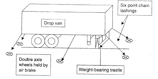
Drop Unit Stowage
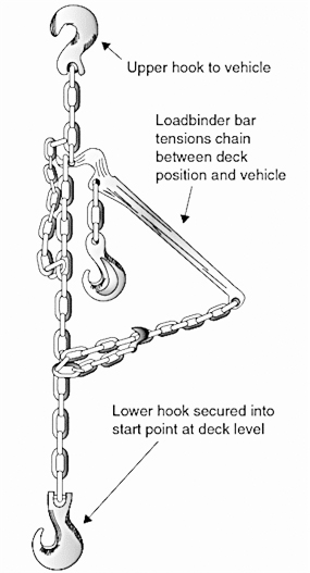
Example of Chain Lashing
Vehicles are built with star lashing points or ‘elephant feet’ type anchor points. Lashings have club foot fitting into these points, with a hook at the opposite end. Alternately, hooks are used at each end.
Procedures for Opening, Closing and Securing of hull openings on Ro-Ro Ships:
The documentation must enable the user to operate the shell doors, inner doors and ramps, if applicable, in a safe manner. The closing and securing functions need to be described particularly clear. Besides safety precautions also the maneuvers running automatically must be explained in detail in order to provide a full understanding of the functions.
References shall be given for troubleshooting of faults and failures and measures to be taken consequently. Emergency stops and emergency operation e.g. in case of energy supply loss shall be described.
The documentation on the operating procedures is to be posted on board at appropriate places.
Problem areas of Ro-Ro vessels:
- The Problem of Stability: – If a vessel maintains its stability at sea then it is safer to sail. However, the problem with the RO-RO ship is its design, which includes cargo in upper decks and accommodation at even higher levels. Even a minor shift of cargo in the ro-ro vessel can become a major threat to the stability of the ship. Similarly, hull failure leading to flooding can result in capsize of the vessel in no time. The effects of wind and bad weather on high accommodation can also disturb the ship’s stability.
- High Freeboard: – In Ro-Ro ships which carry only cargo, the general arrangement of cargo access door is close to the water line. In the event of listing, the door can get submerged leading to high chances for ingress of water inside the ship which will lead to capsize.
- Cargo Access Door: – As discussed above the effect of listing of the ship leads to ingress of water if the cargo doors are open or damaged. One weak point of ro-ro vessel is that sometimes the cargo door itself is used as a ramp which makes the ship more vulnerable to damages.
- Lack of Bulkheads: – The subdivision of ro-ro ship from inside lacks from the transverse bulkheads, leading to lower water tight integrity when water ingress or flooding takes place. Lack of bulkhead also leads to spreading of fire more quickly as no subdivision is present to contain the fire.
- Location of Life Saving Appliances (LSA):- When a ship is to be abandoned, life raft and lifeboats are used to leave the ship as soon as possible. The location of lifeboat and life rafts on ro-ro ships is usually very high, which makes it even difficult to lower them at sea especially when the ship is listing.
- Weather condition: – Another reason which acts externally on the Ro-Ro vessel is the rough weather, which may result in reduction in the stability and cause heavy rolling of the ship. Heavy rolling has lead to capsizing of ships in the past.
- Cargo stowage: – Cargo stowage is very important operation on Ro-Ro vessel for any loose cargo (trailer, cars etc.) can give rise to a chain reaction leading to heavy shift in cargo position. The trucks and trawlers loaded on board also carry cargo inside them and any shift of that cargo can also lead to listing of the ship.
- Cargo Loading: – It is very difficult to have a sequential loading of cargo as cargo arrives on terminals at different intervals and due to lack of time on port. This further leads to uneven cargo distribution, something for which nothing can be done about. Lack of proper cargo distribution has been the reason for several ship accidents in the past.