Principle & Working of Doppler Log:
- Equipment
to measure ship’s speed. - The
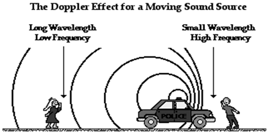
Doppler log is based on measurement of the Doppler effect. - The
Doppler effect can be observed for any type of wave – water wave, sound wave,
light wave, etc. we are most familiar with the Doppler effect because of our
experiences with sound waves. For instance, a police car or emergency vehicle
was travelling towards us on the highway. As the car approached with its siren
blasting, the pitch of the siren sound (a measure of the siren’s frequency) was
high; and then suddenly after the car passed by, the pitch off the siren sound
was low. That was the Doppler Effect – an apparent shift in frequency for a
sound wave produced by a moving source. - The Doppler Effect is a frequency shift that results
from relative motion between a frequency source and a listener. - If
both source and listener are not moving with respect to each other (although
both may be moving at the same speed in the same direction), no Doppler
shift will take place. - If
the source and listener are moving closer to each other, the listener will
perceive a higher frequency – the faster the source or receiver is
approaching the higher the Doppler shift. - If
the source and listener are getting further apart, the listener will perceive a
lower frequency – the faster the source or receiver is moving away the lower
the frequency. - So,
the Doppler shift is directly proportional to speed between source and
listener, frequency of the source, and the speed the wave travels.
Explanation of how ship’s speed is transmitted to remote displays:
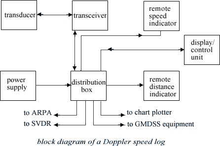
- Distance recording is achieved by using a constant speed motor (10) which drives the distance counter (11), via friction gearing.
- The constant speed motor has been used in order that a distance indication may be produced that is independent of the non-linear characteristic of the system.
- The motor is started by contact (5) as previously described.
- The main shaft (7), whose angle of rotation is directly proportional to the speed of the ship, is fitted with a screw spindle (12).
- The rotation of the shaft causes a lateral displacement of the friction wheel (13). At zero speed, the friction wheel rests against the apex of the distance cone (14), whilst at maximum speed the wheel has been displaced along the cone to the rim.
- The distance indicator (11) is driven from the constant speed motor (10) via the cone.
- The nearer to the rim of the cone the friction wheel rides, the greater will be the distance indication.
- Revolutions of the distance shaft (15) are transmitted to the remote distance indicator via the servo transmission system (16 and 17).
- The speed unit provides the following outputs to drive both speed and distance counters:-
- An analogue voltage, the gradient of which is 0.1 V/knot, to drive the potentiometer servo-type speed indicators.
- A pulse frequency proportional to speed.
- The frequency is 200/36 pulses/s/knot. Pulses are gated into the digital counter by a 1.8-s gate pulse.
- A positive/negative voltage level to set the ahead/astern indication or the B track/W track indication.
- 2000 pulses per nautical mile to drive the stepping motor in the digital distance indicator.
FORMULA of Doppler Log:-
- Doppler effect can be further explained by following equations:
- fr is the frequency received by observer.
- ft is the transmitted frequency.
- c is the speed of sound.
- vO is Velocity of observer
- vg is Velocity of source
- If the source moves towards stationary observer, fr = c ft / (c – vg)
- If the source moves away stationary observer, fr = c ft / (c + vg)
- If the observer moves towards stationary source, fr = ft (c + vg) / c
- If the observer moves away from stationary observer, fr = ft (c – vg) / c
- If the observer & source moves away from each other, fr = ft (c – vg) / (c + vs)
- If the observer & source moves toward each other, fr = ft (c + vg) / (c – vs)
- Since,
in the case of the Doppler log, the source & observer are the same.
Hence,
vO is equal to vS, is equal to v
fr = ft (c+ v) / (c – v)
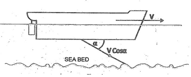
fr = ft (c+ v cos a) / (c – v cos a)
After Further simplification
v = c (fr – ft) / 2 ft cos a
- Given
a propogation angle of 60O, cos a = 0.5 (using single transducer
facing forward) - Graphs
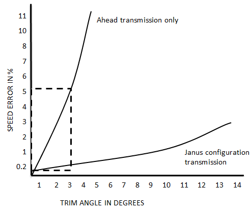
of speed error caused by variations of the vessel’s trim:
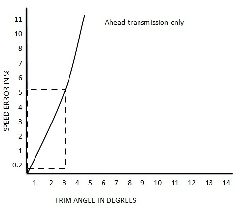
- It
follows that if the angle changes, the speed calculated will be in error
because the angle of propagation has been applied to the speed calculation
formula in this way. If the vessel is not in correct trim (or pitching in heavy
weather) the longitudinal parameters will change and the speed indicated will
be in error. - To
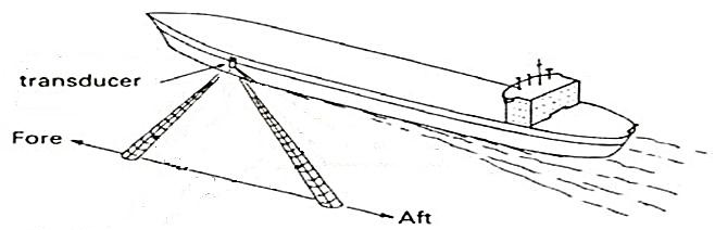
counteract this effect to some extent, two acoustic beams are transmitted, one
ahead and one astern. The transducer assembly used for this type of
transmission is called a ‘Janus’ configuration after the Roman god who
reputedly possessed two faces and was able to see into both the future and the
past.
After installing transducer facing aft, the Doppler frequency shift formula now becomes:-
Frt – fra – 4 vft cos a / c
Hence, v = c (frt – fra) / 4 ft cos a
- Therefore
the transmission angle can effectively be ignored. - The
advantage of having a Janus configuration over a single transducer arrangement.
It can be seen that a 3O change of trim on a vessel in a forward
pointing Doppler system will produce a 5 % velocity error. With a Janus
configuration transducer system, the error is reduced to 0.2% but is not fully
eliminated.
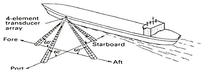
- The addition of a
second transducer assembly set at right angles to the first one, enables dual
axis speed (longitudinal speed and transverse speed) to be indicated.
Docking Operation:
- The placing of the Janus configuration in a fore and aft direction is known as a single axis system and is used to calculate speed over ground in the forward and after direction. A dual axis system places a second grouping of Janus configured transducers in an athwart ships direction allowing for the calculation of a vessel’s speed when moving sideways through the water, as in docking. The beam width of the athwart ship installation is about 8 degrees to account for the possibility of a vessel’s rolling.
- The Doppler system calculates speed to within an accuracy of about 0.5 percent of the distance traveled. It functions well for all speeds that modern vessels can attain and works from a minimum depth of about 1.5 feet to a maximum depth of about 600 feet. Frequencies employed are between 100 kHz and 600 kHz. There are primarily four errors to be aware of when using the Doppler system:
- Transducer orientation error caused when the pitching or rolling of the vessel becomes excessive.
- Vessel motion error caused by excessive vibration of the vessel as it moves through the water.
- Velocity of sound errors due to changes in water temperature or density due to salinity and particle content.
- Signal loss errors caused by attenuation of the vibrations during transit through the water or upon reflection from the bottom.
- The Doppler system normally measures speed over ground to about 600 feet. This depth signals may be returned by a dense, colder layer of water located throughout the oceans called the deep scattering layer (DSL). Signals received off the DSL are not as accurate as signals received from bottom reflections but can still be used to provide an indication of speed through the water instead of speed over ground when bottom tracking. Your unit may have a manual or automatic system which will switch from bottom tracking to water tracking at increased depth.
- The Doppler system can be connected with other electronic navigation systems providing generally accurate speed input. The navigator should be cautioned that precise speed should be determined not only by using the Doppler but also from careful calculations of distances between accurate navigational fixes.
Errors in a Doppler log & how are some of these errors overcome by the Janus Configuration:
ERRORS OF DOPPLER LOG:- The Log speed indicated is subject to various errors, spanning installation, equipment, data processing, varying propagation conditions and sea conditions.
- Error in transducer orientation:- The transducers should make a perfect angle of 60° with respect to the keel or else the speed indicated will be inaccurate.
- Error in oscillator frequency:- The frequency generated by the oscillator must be accurate and constant. Any deviation in the frequency will result in the speed showing in error.
- Error in propagation:- The velocity of the acoustic wave at a temperature of 16°C and salinity of 3.2% is 1505 m/sec but taken as 1500 m/sec for calculation. This velocity changes with temperature, salinity and pressure. To compensate the error due to temperature change, a thermister is mounted near the transducer and change in velocity of the acoustic wave through the water from the standard value due to the change in sea water temperature is accounted for.
- Error in ships’ motion:- During the period of transmission and reception, the ship may have a marginal roll or pitch and thereby the angle of transmission and reception can change and a two degree difference in the angle of transmission and reception can have a 0.10% error in the indicated speed, which is marginal and can be neglected.
- Error due to rolling/pitching:- The effect of pitching will cause an error in the forward speed and not the athwartship speed. Similarly, rolling will have an effect on the athwartship speed, not the forward speed.
Actual speed = Indicated speed/Cosß
- Error due to inaccuracy in measurement of frequency:- The difference
in the frequencies received by the forward and aft transducers must be measured
accurately. Any error in this will be directly reflected in the speed of the
vessel. - Error due to side lobe:- When the side
lobe reception dominates over the main beam reception, there will be an error
in the speed indicated. The error is more pronounced on a sloping bottom as the
side lobe is reflected at a more favourable angle and will have path length
less than the main beam. This error can be eliminated with the help of the
Janus configuration and to reduce this error, the beam of the transmitted
acoustic wave is reduced.
THE ‘SPEED’ FORMULA WITH SHIP MOVEMENTS CORRECTION – JANUS CONFIGURATION:-
As the ship moves forward, she also has an up and down motion in the vertical direction, called ‘heaving’. The vertical motion component is v sin α.
As this movement of the ship has an effect on the frequency shift, it should be accounted for. This is done by installing a second set of transducers (for transmitting and receiving) in the aft direction at the same angle of 60º. (Refer figure). This type of installation setup is called Janus Configuration.
The effect of frequency shift due to vertical motion (the component v sin α ) of the ship gets cancelled out in Janus Configuration and the resultant ship speed is calculated by the formulae:
v = c (Frf – Fra) / 4 Ft cos α
Where,
- v= ship’s speed
- c= speed of acoustic wave in water
- Frf = Freq. of the received wave, from fwd direction
- Fra = Freq. of the received wave, from aft direction
- Ft = Freq. of the transmitted wave
- α = angle of acoustic wave transmission