Basic Principles of Echo Sounder:
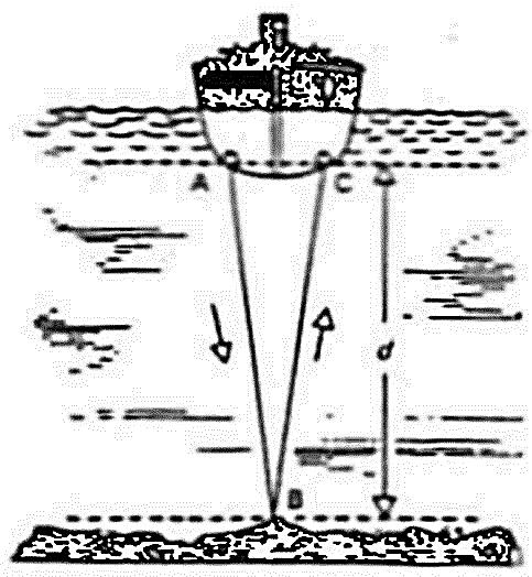
Short pulses of sound vibrations are transmitted from the bottom of the ship to the seabed. These sound waves are reflected back by the seabed and the time taken from transmission to reception of the reflected sound waves is measured. Since the speed of sound in water is about 1500 m/sec, the depth of the sea bed is calculated which will be half the distance travelled by the sound waves.
The received echoes are converted into electrical signal by the receiving transducer and after passing through to stylus which burns out the coating of the thin layer of aluminum powder and produces the black mark on the paper indicating the depth of seabed.
Components of Echo Sounder:
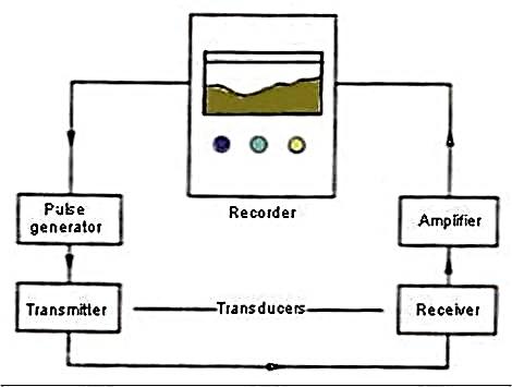
- Basically an echo sounder has following components:
- Transducer – to generate the sound vibrations and also receive the reflected sound vibration.
- Pulse generator – to produce electrical oscillations for the transmitting transducer.
- Amplifier – to amplify the weak electrical oscillations that has been generated by the receiving transducer on reception of the reflected sound vibration.
- Recorder – for measuring and indicating depth.
CONTROLS:-
- An echo sounder will normally have the following controls:
- Range Switch – to select the range between which the depth is be checked e.g. 0- 50 m, 1 – 100 m, 100 – 200 m etc. Always check the lowest range first before shifting to a higher range.
- Unit selector switch – to select the unit feet, fathoms or meter as required.
- Gain switch – to be adjusted such that the clearest echo line is recorded on the paper.
- Paper speed control – to select the speed of the paper – usually two speeds available.
- Zero Adjustment or Draught setting control – the echo sounder will normally display the depth below the keel. This switch can be used to feed the ship’s draught such that the echo sounder will display the total sea depth. This switch is also used to adjust the start of the transmission of the sound pulse to be in line with the zero of the scale in use.
- Fix or event marker – this button is used to draw a line on the paper as a mark to indicate certain time e.g. passing a navigational mark, when a position is plotted on the chart etc.
- Transducer changeover switch – in case vessel has more than one switch e.g. forward and aft transducer.
- Dimmer – to illuminate the display as required.
Working:
- The acoustic pulses of very short duration are transmitted vertically at the rate of 5 to 600 pulses per minute having a beam width of 12 to 25°.
- These pulses strike the seabed and get reflected back towards the receiving transducer as echoes.
- These received echoes are converted into electrical signals by the receiving transducer and after passing through the different stages of the receiver, the current is supplied to the stylus which bums out the coating of the thin layer of aluminium powder and produces a black mark on the paper indicating the depth of the seabed.
-
 Bridge Watchkeeping 2nd Mate Solved Past papers till May’26₹ 241.00
 -
 Bridge Watchkeeping, Safety Solved MMD Past Papers Phase 2 Chief Mate till February’26₹ 242.00
 -
 2nd Mate Oral Function 1 Notes (F.G.)₹ 164.00
 -
 Chief Mate Orals Function 1 FAQ Notes₹ 207.00
 -
 Bridge Watchkeeping NCV (NWKO) Solved Past papers till Jan’20₹ 117.00
 -
 Function 1 – Chief Mate Orals Notes by Sagar Das₹ 255.00
Principle used in the working of an Echo Sounder:-
There are two techniques:-
- Ranging
- Phasing
Ranging:-
- In echo sounder the stylus is mounted on circular belt driven by means of a stylus motor which moves at certain speed and transmission takes place when the stylus passes the zero marks.
- A magnet fixed on the stylus belt triggers the transmitter to transmit a pulse every rotation of belt when stylus is at zero mark on the paper scale, the transmission of the acoustic waves from the transducer is synchronized with the stylus at the zero mark.
- The acoustic waves are reflected from the seabed and echoes are received by the transducer and after passing through various stages eventually the current is supplied to stylus which burns out the coating of the thin layer of aluminum powder and produces the black mark on the paper indicating the depth of seabed.
- This cycle is repeated for every rotation so as the paper is pulled across the display, the profile of seabed is obtained.
- Suppose the lowest range scale is 0 to 50 M, the transmission will take place when stylus reaches at the zero mark.
- When the higher range is selected say 0 to 100 M, in order to cater for this range scale, the speed of the stylus motor is reduced, in this process the scale magnification is lost and as we switch over to higher ranges the scale becomes more & more congested.
- To overcome this problem some of echo sounding machines work on phasing technique.
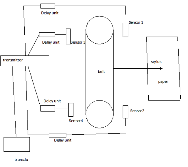
Phasing:-
- In phasing the speed of the stylus motor remains constant.
- Instead of changing the speed of the stylus, the transmission point is advanced.
- If the first range is 0 to 50 M the second range will be 50 to 100 M (instead of 0 to 100 M).
- Various sensors are positioned around the stylus belt, the magnet generates the pulse when it passes the sensors which in turns activates the transmitter.
- In the below diagram, when we select the lowest range i.e. 0 to 50 M, the magnet mounted on the stylus belt will activate sensor no. 1, transmission takes place when the stylus exactly passes over the zero mark, when we switch over to higher range, say 50 to 100 M, the magnet mounted on the stylus belt will activate sensor no.2 and transmission will take place early, at the time of the transmission, the stylus will not be passing over 50 M mark on display unit, in other words there will be delay introduced by delay unit no.2 & the stylus will reach the 50 M on display unit after delay of 0.067 seconds. (50 x 2 / 1500, where 50 correspond to the range, multiplied by 2 because double of distance is covered by acoustic waves & the echoes and 1500 is the speed of acoustic waves).
- Likewise, when we switch over to higher range say, 100 to 150 M, magnet mounted on the stylus belt will activate sensor no. 3 & more delay will be introduced for the stylus to pass over the 100 M.
Caution when using phasing technique: – We must always start sounding at lowest range and check for echoes, adjust the gain control if required and then only switch over to higher range.
Errors of Echo Sounder:
- Velocity of propagation in water:- The velocity changes with temperature salinity & pressure. The velocity of the acoustic wave assumed at the temperature of 16 degree C & Salinity of 3.4% is 1505 m/sec, but generally it is taken as 1500 m/sec for calculations. As velocity is varying hence depth recorded will be erroneous. Depth indicated in Fresh water can be about 3% higher than the actual depth. NP 139 can be referred in order to obtain the corrections. To compensate the error due to temperature variation, a component called “thermistor” may be mounted near the transducer & change in velocity of the acoustic wave through water from the standard value due to the change in sea water temperature is accounted for. Error due to pressure is not so significant.
- Stylus speed error:- The speed of the stylus is such that the time taken by the stylus to travel from top to bottom on chart is same as the time taken by sound waves to travel twice the range selected, but due to fluctuation in voltage supplied to stylus motor, will cause error in the recorded depth.
- Pythagoras error:- This error is found when two transducers are used, one for transmission and the other one for reception. This error is calculated using the Pythagoras principle. This error becomes prominent whenever distance between two transducer is more than 2 mtrs, manual should be referred in order to use the table for corrections.
- Multiple echoes:- The echo may be reflected no. of times from the bottom of the sea bed, hence providing the multiple depth marks on paper.
- The thermal and density layers:- The density of the water varies with temperature and salinity, which all tends to form different layers. The sound wave may be reflected from these layers.
- Zero line adjustment error:- If the zero is not adjusted properly, it will give error in reading.
- Cross noise:- If sensitivity of the amplifier is high, just after zero marking a narrow line along with the several irregular dots and dashes appear and this is called cross noise. The main reasons for the cross noise are aeration and picking up the transmitted pulse. If intensity of cross noise is high, it will completely mask the shallow water depths. This is controlled by swept gain control circuit.
- Aeration:- When the sound wave is reflected from the reflected from the air bubbles, it will appear as dots, this is known as aeration.
- Aeration can be due to pockets of bubble due to heavy weather.
- Rudder hard over causing drastic alteration of course.
- Pitching in light condition.
- Whilst astern propulsion. (Switch over to forward transducer if available.)
Electrostrictive Transducer with respect to Echo Sounder:
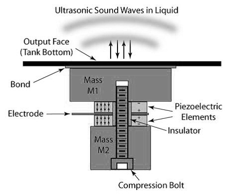
- This type of transducer works on the basic principle of piezo-electric effect, i.e., certain crystals such as quartz, have a property that when pressure is applied to the two opposite faces, a difference of potential is created which is proportional to the applied pressure or when an alternating voltage is applied,
the crystals start vibrating or oscillating. This type of transducer is also known as Piezostrictive transducer. - The electrostrictive transducer uses the property of a crystal for transmission and reception of acoustic waves in water. The crystal is firmly fixed between two steel plates so that they act as a single unit.
- The purpose of the steel plates is to provide solid and robust housing for the crystal as well as a suitable contact surface for seawater.
- When an alternating voltage is applied between the steel plates, the quartz and the steel plates start vibrating together. The vibration will be of very high amplitude, if the frequency of the alternating voltage is equal to the resonance frequency of the crystal. The lower of the two steel plates is in direct contact with the water, which will cause the vibration in the seawater.
The vibration is always perpendicular to the plate and hence always kept horizontally. - Generally, only one transducer is used for transmission and reception of the signals and this transducer is always mounted as pierced hull.