Posted on Leave a comment

Inspection of Vulnerable Areas

Inspection of Vulnerable Areas in the Dry Cargo Holds for Damages:

When a vessel requires repairs to damaged equipment or to the hull it is necessary for the work to be carried out to the satisfaction of the classification society surveyors. In order that the ship maintains its class, approval of the repairs undertaken must be obtained from the surveyors either at the time of the repair or at the earliest opportunity.

Terminal operators should be aware of the damage that their cargo handling equipment can inflict on the ship’s structure. It is important that the protective coatings in cargo holds and water ballast tanks are maintained.

The cargo holds and deck areas should be inspected by the ship’s deck officers upon completion of cargo discharge to identify any signs of physical damage, corrosion or coating damage to the ship’s structure. Where hull damage is identified, which may affect the integrity of the hull structure and the seaworthiness of the ship, it should be reported accordingly to the classification society.

Cargo watch on deck should monitor stevedore grab handling and damage. Crane drivers should be advised to take care not to damage ship structure cargo watch on deck should monitor ballast operations cargo watch on deck when the ship is carrying water-sensitive cargoes should identify the potential for water to leak from a crack or damage in the hold plating following grab damage consider gravitating ballast, to reduce pressure on ballast tank structures a rigorous sounding regime should be maintained in port.

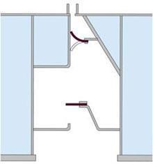
The internal hold structure and protective coatings in the cargo hold and the adjacent double bottom are vulnerable to damage when the cargo is discharged using grabs. The weight of empty grabs can be 35 tonnes. Other types of equipment employed to free and clear cargo, including hydraulic hammers fitted to extending arms of tractors and bulldozers can inflict further damage to the ship’s structure, especially in way of the side shell and the associated frames and end brackets. Chipping (sharp indentations) and the local buckling or detachment of side frames at their lower connection could lead to cracking of the side shell plating which would allow the ingress of water in to the cargo space.

The protective coatings which may be required to be applied in the cargo hold are also subject to deterioration caused by the corrosive nature of the cargo, high temperature cargoes, cargo settlement during the voyage and the abrasive action of the cargo. Where no protective coatings have been applied or the applied protective coatings have broken down, the rate of corrosion in that area will greatly increase, especially when carrying corrosive cargoes, such as coal.

Corrosion will weaken the ship’s structure and may, eventually, seriously affect the ship’s structural integrity. The severity of the corrosion attained by a structural member may not be easily detected without close- up inspection or until the corrosion causes serious structural problems such as the collapse or detachment of hold frames resulting in cracks propagating in the side shell.

Impact damage to the inner bottom plating or the hopper sloping plating will result in the breakdown of coatings in the adjacent water ballast tanks, thereby intensifying the rate of structural deterioration.

Solas 74 as amended Chapter XII: Additional safety measures for bulk carriers Regulation 5: (This regulation applies to bulk carriers constructed on or after 1 July 1999)

Bulk carriers of 150 m in length and upwards of single side skin construction, designed to carry solid bulk cargoes having a density of 1,000 kg/m3 and above, shall have sufficient strength to withstand flooding of any one cargo hold in all loading and ballast conditions, taking also into account dynamic effects resulting from the presence of water in the hold, and taking into account the recommendations adopted by the Organization.

Regulation 6: Structural and other requirements for bulk carriers (This regulation applies to bulk carriers constructed before 1 July 1999):-

  1. Bulk carriers of 150 m in length and upwards of single side skin construction, carrying solid bulk cargoes having a density of 1,780 kg/m3 and above, shall comply with the requirements of this regulation in accordance with the implementation schedule specified in regulation 3.
  2. The transverse watertight bulkhead between the two foremost cargo holds and the double bottom of the foremost cargo hold shall have sufficient strength to withstand flooding of the foremost cargo hold, taking also into account dynamic effects resulting from the presence of water in the hold, in compliance with the bulk carrier bulkhead and double bottom strength standards. For the purpose of this regulation, the bulk carrier bulkhead and double bottom strength standards shall be treated as mandatory.
  3. In considering the need for, and the extent of, strengthening of the transverse watertight bulkhead or double bottom to meet the requirements of paragraph 2, the following restrictions may be taken into account:
    • Restrictions on the distribution of the total cargo weight between the cargo holds; and
    • Restrictions on the maximum deadweight.
  4. For bulk carriers using either of, or both, the restrictions given in paragraphs 3.1 and 3.2 above for the purpose of fulfilling the requirements of paragraph 2, these restrictions shall be complied with whenever solid bulk cargoes having a density of 1,780 kg/m3 and above are carried.

Vulnerable Areas in Ship’s Cargo holds where infestation may take place:

  • Tank top ceiling: If, as often happens, cracks appear between the ceiling boards, food material may be forced down into the underlying space and serve as a focus of infestation for an indefinite period. Insects bred in this space can readily move out to attack food cargoes and establish their progeny in them.
  • ‘Tween-deck centre lines, wooden feeders and bins are often left in place for several voyages and because of their construction are a frequent source of infestation. After unloading a grain cargo, burlap and battens covering the narrow spaces between the planks should be removed and discarded before the holds are cleaned or washed down. These coverings should be replaced by new material in preparation for the next cargo.
  • Transverse beams and longitudinal deck girders which support the decks and hatch openings may have an L-shaped angle-bar construction. Such girders provide ledges where grain may lodge when bulk cargoes are unloaded. The ledges are often in inaccessible places overlooked during cleaning operations.
  • Insulated bulkheads near engine-rooms: When the hold side of an engine-room bulkhead is insulated with a wooden sheathing, the airspace and the cracks between the boards often become filled with grain and other material. Sometimes the airspace is filled with insulating material which may become heavily infested and serves as a place for insect breeding. Temporary wooden bulkheads also provide an ideal place for insect breeding, especially under moist conditions, such as when green lumber is used.
  • Cargo battens: The crevices at the sparring cleats are ideal places for material to lodge and for insects to hide.
  • Bilges: Insects in accumulations of food material are often found in these spaces.
  • Electrical conduit casings: Sometimes the sheet-metal covering is damaged by general cargo and when bulk grain is loaded later, the casings may become completely filled. This residual grain has often been found to be heavily infested. Casings that are damaged should be repaired immediately or, where possible, they should be replaced with steel strapping, which can be cleaned more easily.
  • Other places where material accumulates and where insects breed and hide include:
    • The area underneath burlap, which is used to cover limber boards and sometimes to cover tank top ceilings.
    • Boxing around pipes, especially if it is broken.
    • Corners, where old cereal material is often found.
    • Crevices at plate landings, frames and chocks.
    • Wooden coverings of manholes or wells leading to double-bottom tanks or other places.
    • Cracks in the wooden ceiling protecting the propeller shaft tunnel.
    • Beneath rusty scale and old paint on the inside of hull plates.
    • Shifting boards.
    • Dunnage material, empty bags and used separation cloths.
    • Inside lockers.
Posted on Leave a comment

Macgregor Hatch Cover on board of bulk carrier

Maintenance of Macgregor type of steel hatch cover on board of bulk carrier.

Poor maintenance of hatch covers causes leakage leading to cargo damage and represents a hazard to the ship and its crew. Although hatch covers are simple and durable, their sealing gaskets are easily damaged. The quality of sealing is affected by lack of alignment and poor gasket compression. When hatch covers are opened at the end of an ocean voyage, look for signs of leakage such as rust staining or drip marks.

Regular adjustment and repair, by ship’s staff, will reduce the overall cost of maintenance. Painting double drainage channels will help to prevent corrosion.

Always keep a detailed record of maintenance. Take care during extensive hatch cover repair to avoid cover distortion.

Rubber Gaskets: -Keep clean and free from paint. If physically damaged, permanently set-in or aged, replace with minimum 1 metre lengths. Always follow the manufacturer’s instructions when renewing gaskets.

Macgregor Hatch Cover - Rubber Gaskets
Macgregor Hatch Cover – Rubber Gaskets

Gasket Channels:- If gasket channels are badly corroded, causing the hatch packing to hang loose, the packing should be removed and the channel repaired by welding new metal strips which should be painted before fitting new rubber. Always follow proper fire prevention safety procedures. Make sure that cargo spaces are free of cargo and combustible material. When conducting extensive structural repairs, remove the hatch covers to shore.

Macgregor Hatch Cover - Gasket Channels
Macgregor Hatch Cover – Gasket Channels

Hatch Cover Structure:- Repair or replace any damaged, worn or defective hatch covers or comings. Consult with the ship’s classification society before commencing repair. Paint new structure immediately.

Compression Bars:- Effective sealing is only possible with a straight, undamaged and non-corroded compression bar. Compression bars which are not in this condition should be repaired or replaced, taking care to align the bars properly. Remember to carry out a chalk test to check alignment, both during and after repair.

Landing Pads:- Hatch sealing is arranged by design to give the correct compression of the gasket when there is metal-to-metal contact on the hatch landing pad, side plate, or inter panel block. If landing pads are reduced in height (check with manufacturers’ drawings) because of wear, repair is essential.

Hatch Wheel Track Ways:- Track ways can corrode. They are weakened by abrasive wear and tear. When weakened, track ways can distort and break, affecting hatch movement and alignment. Deterioration is visible to the naked eye. Repair by replacing the worn or damaged material with sufficient new material to restore strength. Always keep hatch wheel track ways clean and painted.

Macgregor Hatch Cover - Hatch Wheel Track Ways
Macgregor Hatch Cover – Hatch Wheel Track Ways

Hatch Coamings:- Look for cracks at coaming corners. If any are found, consult the ship’s classification society before commencing repairs in case the coaming needs to be reinforced. Examine coaming support brackets for corrosion where they connect with the ship’s deck. Make sure coamings and their support brackets are painted. Coamings can be damaged by cargo equipment during loading or discharge. Look out for damage and repair if found.

Macgregor Hatch Cover - Hatch Cleats and Wedges
Macgregor Hatch Cover – Hatch Cleats and Wedges

Hatch Cleats and Wedges:- It is important for compression washers to be adjusted correctly. A locking nut for adjusting compression is situated at the base of the cleat. The procedure to alter compression (see illustrations) is as follows:

  • Close hatch and secure for sea;
  • Place the cam of the cleat in the hatch socket as if to lock it, but leave it unlocked (the cam should move freely and fit snugly in its housing);
  • Adjust the locking nut until the compression washer touches the underside of the hatch coaming or its steel washer;
  • Turn the locking nut one full turn to achieve the desired tension;
  • Do not over-tighten;
  • Protect the thread on completion.

When closing and securing a hatch for sea passage, check the tension in side cleats. Cleats should never be adjusted in isolation, adjust all cleats along the hatch skirt at the same time.

Hatch Cross-Joints:- It is essential for the cross-joint to be in good condition and properly aligned.

Maintenance and repair should focus on:

  • Examination of the cross-joint structure for corrosion.
  • Examination of joint hinges for pin wear, blade cracking or weld failure.

(Re-grease the hinge pin bushes making sure grease reaches the hinge pins).

  • Examination of the steel-to-steel inter-panel blocks and locators for wear. (Check the top plate of hatch panels, they should be level when closed).
  • Checking the gap between panels when they are closed. Misalignment could be caused by an incorrectly adjusted cylinder or the wheel tracks could be worn.

Hatch Wheels:- Hatch wheel spindles and bearings (where fitted) need to be greased regularly. Check the wheel spindle for wear and the wheel housing for physical damage. Repair if the spindle is worn or if the wheels are out of alignment.

Drain Channels and Non-Return Valves:- Clean coaming tops and cross-joint channels by removing any loose scale or cargo residue by brushing or hosing. Clean coaming drain holes and check that the nonreturn valve is functioning.

Greasing:- Wheel spindles, cleat spindles, hinge pins, hydraulic cylinder protective sheaths, cleat wedges, drive chain sprockets, toothed rack and cylinder spherical bearings need to be kept well-greased. Re-grease every month if necessary, and always apply new grease after the ship has passed through heavy weather.

Painting:- Corrosion occurs mainly at the panel ends along the cross-joint or where access is difficult, but it can also occur on the underside of a panel, especially along hatch beams. Regular painting will be necessary.

Inert Gas:- Hatch covers with a double skin, in the form of a closed box, are filled with inert gas. After structural repair, the inner spaces must be re-inerted. This is done by inserting special tablets (available from the hatch cover manufacturer) into the space and welding shut. Never allow water to penetrate the box construction.

Hydraulic Systems and Components:- The cleanliness and viscosity of hydraulic oil must be checked. Samples of the oil should be sent to a chemist for testing (use the same company that checks and tests your fuel and lubricating oil). The hydraulic system is provided with bleed points from which samples can be taken. Hydraulic oil should be changed every five years or after there have been significant repairs, such as piping or cylinder replacement. Hydraulic oil filters should be changed every twelve months. Do not contemplate repairing the hydraulic system without the proper components and skilled fitters.

Posted on Leave a comment

Testing & Inspection of Hatch Covers

Testing of Hatch Covers – Weather Tightness:

After maintenance procedure it is advised to test the water tight integrity of the hatch cover by different methods. The three methods to check water tightness of hold covers are:

Hose water Test:

In this test a water spray from a nozzle of 12mm diameter is sprayed over the joint of hold and cover from a distance of 1m to 1.5 m with a pressure of 0.5 m/ second water jet.

Hatch Cover - Hose Water Test
Hatch Cover – Hose Water Test
  • The limitation or drawbacks of this test is that it requires two persons and hatch cover to be tested must be empty.
  • The leakage if very minimal cannot be identified by naked eye and cannot be performed in sub zero or cold weather.

Advantages:-

  • The hose test is the traditional way of testing hatch covers.
  • It is an inexpensive method as a fire hose with nozzle & a good water pressure from the fire pump is the only primary requirement.
  • It can be useful to have good results of hatch cover tests entered in the logbook.

Disadvantages:-

  • Surplus amount of sea water required for performing the test.
  • Sometimes have resulted in cargo damage.
  • From a surveyor’s point of view, the hose test also has the disadvantage of not being fool proof. The surveyor will not be able to observe how the spraying is performed on the outside, while he is the cargo hold looking for leakages.
  • If a hard water jet is not armed directly over the hatch cover joints, then the test may prove worthless.

Chalk Test:

  • The Chalk Test is often carried out when the vessel is new in the shipyard.
  • All the compression bars are rigorously rubbed with a piece of chalk thereafter the hatch covers are put in place & secured and then opened  again.
  • If there has been insufficient compression between the compression box and the hatch cover gasket there will be lack of or incomplete chalk marks in such areas of gaskets.

Advantages:-

  • It clearly defines the persisting problem in achieving weather tightness.
  • It also marks if the gasket lands off-centre on the compression bar.

Disadvantages:-

  • Surplus amount of chalk required to cover the full periphery of the compression bar length.
  • The method is rather time consuming and can only be used in dry weather.

Ultra Apparatus Test:

One of the possible applications for using ultrasounds in the marine industry consists of testing the weathertight integrity of hatch covers, weathertight doors, ventilators, on board of ships. The testing principle is based on the generation of a distinctive ultrasonic signal by using a transmitter (SDT 200mW for small compartments and SDT 8 MS for larger compartments) which is placed inside the compartment to be tested. Through reflection, the ultrasounds generated by the transmitter will fill up the cargo hold.

Ultrasounds passing through sealing arrangements, cracks, holes etc. can easily be picked up and measured by the SDT Sherlog ultrasonic receiver equipped with a handy flexible sensor.

        Positioning the transmitter in the hold     Checking sealing arrangements for leaks:-

Hatch Cover - Ultra Apparatus Test
Hatch Cover – Ultra Apparatus Test

Advantages:-

Testing hatch covers, or other cargo access equipment such as bow-doors, visors, ramps, etc., with ultrasonic testing equipment offers the surveyor or inspector several advantages. The most important benefits of using ultrasonic testing material are:

Reliable, Non-destructive, repeatable testing method:

  • Detection of areas where lack of compression exists with pin-point accuracy (no time consuming investigation needed for finding the leaks, as the leak can be pin-pointed local repairs might be sufficient and adequate,….).
  • Information about compression status.
  • Quick and easy testing, without assistance from ship’s crew (except for supervision and safety aspects).
  • Possibility to use the equipment in holds loaded with water susceptible cargo.
  • Possibility to test hatch covers irrespective of weather conditions.
  • Testing for weathertightness and air/gas tightness.
  • Identification of leaks without the use of a transmitter (on condition that the compartment tested for leaks is pressurised (air escaping through small openings, cracks etc… will cause disturbance of molecules/friction which creates ultrasounds that can be detected)).

Carrying out Hatch Cover Inspection w.r.t. Load Line Survey:

Guide Notes for Hatch Covers of Dry Cargo Ships Survey:
  1. Statutory surveys of hatch covers and their coamings are to be carried out by the Administration as part of the annual survey required by article 14 of the International Convention on Load Lines, 1966, as modified by the 1988 Protocol relating thereto. The International Maritime Organization (IMO) adopts the International Code on the Enhanced Program of Inspections During Surveys for Bulk Carriers and Oil Tankers, 2011 (2011 ESP Code) by means of the Resolution A. 1049 (27) regarding IMO mandatory inspection regime for tankers and bulk carriers which contains the approved text as set out in the annex to this Resolution.
  2. A thorough survey of hatch covers and coamings is only possible by examination in the open as well as closed positions and should include verification of proper opening and closing operation. As a result, at least 50% of hatch cover sets should be surveyed open, closed and in operation to the full extent in each direction, at each annual survey. The closing of the covers should include the fastening of all peripheral, and cross joint cleats or other securing devices. Particular attention should be paid to the condition of hatch covers in the forward 25% of the ship’s length, where sea loads are normally greatest.
  3. If there are indications of difficulty in operating and securing hatch covers, additional sets above those required by 2, at the discretion of the surveyor, should be tested in operation.
  4. Owners and operators should ensure that facilities and personnel are available to perform the required hatch cover movements during each annual survey.
  5. It is implicit that if the hatch securing system cannot be properly operated, the ship will be obliged to effect repairs under the supervision of the Administration. Where hatch covers or coamings undergo substantial repairs, the strength of securing devices should comply with IACS UR S30.
  6. Owners and operators should be made aware that partial replacements in cleating systems have the potential to introduce imbalance between old and new cleats. This could result in isolated cleats being subjected to excessive loads, which may then lead to sequential failure.
  7. For each hatch cover set, at each annual survey, the following items should be surveyed:
    • cover panels, including side plates, and stiffener attachments of opened covers, by close up survey (for corrosion, cracks, deformation);
    • sealing arrangements of perimeter and cross joints (gaskets for condition and permanent deformation, flexible seals on combination carriers, gasket lips, compression bars, drainage channels and non-return valves);
    • clamping devices, retaining bars, cleating (for wastage, adjustment, and condition of rubber components);
    • closed cover locating devices (for distortion and attachment);
    • chain or rope pulleys;
    • guides;
    • guide rails and track wheels;
    • stoppers;
    • wires, chains, tensioners and gypsies;
    • hydraulic system, electrical safety devices and interlocks; and
    • end and inter-panel hinges pins and stools where fitted.
  8. At each hatchway, at each annual survey, the coamings, with plating, stiffeners and brackets should be checked for corrosion, cracks and deformation, especially of the coaming tops.
  9. Where considered necessary, the effectiveness of sealing arrangements may be proved by hose or chalk testing supplemented by dimensional measurements of seal compressing components.
Posted on Leave a comment

Maintenance of Hatch Covers

Procedure for Maintenance of Hatch Covers:

The watertightness of hatch covers is imperative to protect the cargo and avoid large cargo claims. The vessel’s maintenance program for testing & maintenance of hatch covers should also include recommended instructions from hatch cover manufacturers. Due to frequent operation of the hatch cover requires constant maintenance of various moving and non-moving parts including renewals as listed below:

Rust removal from steel work:- The top & sides of the hatch covers, coamings & stays must be thoroughly checked for signs of corrosion and reduction in plate thickness. Areas particularly liable to corrosion include welded seams on the hatch top, edges of pontoons, drain channels, circumference of lightning holes in stays, edges of flanges or brackets, shadow areas  such as behind accentric wheels where chipping devices cannot reach underside of the trackway, retaining channel for rubber packing, etc.

Cleaning:- Dirt & Cargo residues or the trackway and rubber packing will prevent watertightness.

Compression Bars:- Compression bars must be of an even height, with a rounded profile and no sharp edges due to corrosion as this could damage the rubber packing. If uneven, they must be built up by welding or ground to an even height. Extremely bad lengths are to cropped & renewed. Compression bars are often made of stainless steel for long life to avoid the problems mentioned above.

Rubber Packing:- The rubber packing all around the hatch cover and across each panel should be in good condition, elastic & not hardened. The point is t have gaskets of sufficient residence to achieve tightness when resting against compression bars of adjoining panels and hatch coamings. Rubber packing should be protected from paint and chemicals. The retaining channels in which the packing sits should be free of corrosion. Rubber packing is to be replaced if damaged or compressed to less than 80% of original size. Rubber packing cannot be repaired in bits & pieces as uneven compression will result. The entire length must be replaced. The retaining channel must be chipped & painted prior to renewal of rubber packing.

Eccentric Wheels & Balancing Wheels:- Eccentric wheels should freely rotate even by hand. They should be greased atleast once a month especially after a long voyage. Every six months depending on their use they should be opened up, cleaned greased and the bearings renewed if necessary. Wheel bush wheel pin must be replaced if there is more than 1 mm of wear down.

Towing Chains:- Towing chains are susceptible to elongation as they bear a lot of stress when pulling the covers. If elongated a gap will appear between adjoining panels when closing. However any elongation means deformation and weaking and loss of strength. If elongation exceeds 5 % of its original length that particular length of chain must be replaced.

Quick acting cleats:- Quick acting cleats and screw bolt cleats pull the hatch cover down tight over the coaming. Thus, compressing the rubber packing. The length of the cleat should be adjusted by a nut so as to produce just the right amount of compression. On old cleats the rubber washer often hardens & the threads should be protected from corrosion by greasing.

Resting Pads:- The full weight of the hatch covers is not supposed to be borne by gaskets alone, only to the extent that the correct design compression of the gasket is achieved  and then limited by the hatch cover resting steel to steel on coaming top on designed resting pads. Wear and corrosion of the resting pads or where these are not fitted, reduction of the lower edges of hatch covers and the corrosion of contact area of the hatch coaming top should be avoided by proper maintenance.

Guttes & Drain pipes:- Cross over joints between panels will have gutters fitted underneath the packing to accumulate small amounts of water penetrating. These gutters will drain the water to the hatch coaming gutters and it is important to check that they are not fractured or damaged at the ends so water drains down the inside of the coamings instead. The hatch coaming gutters will drain the water aft to drain pipes. They should be kept clean of all remains of cargo before battering down. Non-return valve of the drain pipes should be checked for clogging by duster cargo residues and tested for efficient functioning.

Pull Wire:- The pull wire for the covers should be in good condition & greased. Blocks through which it is led must be regularly checked & maintained.


Planned Maintenance System for Hatch Covers:

Bulk carrier hatch cover maintenance standards:

As per IMO /MSC/Circ.1071 Ship owners and operators are recommended to maintain a record of maintenance, and component replacement, to facilitate statutory surveys by the Administration.

All major repairs should be undertaken only after consultation with the hatch cover manufacturer and with the approval of the Administration. Hatch cover maintenance plans should form part of a ships safety management system as referred to in the ISM Code.

Although the PMS has an ongoing system both for renewals and maintenance regime, it is recommended that vessels maintain a simple checklist as per makers instructions is advisable to be maintained on board and the checklist should cover the below items.

After Each cargo operation:

  • Clean the coaming tops and remove any debris or equipment.
  • Clear drain line holes and valves of debris.
  • Drain valve caps should be attached by chain, but not screwed on. They must be ready in case of a fire in the hold or when carrying out fumigation operations.
  • Grooves and worn landing pads can be built up with welding and ground down, as required, giving a permanent repair.
  • Check and clean the surface of the seals and take special care if the cargo is dusty or gritty.
  • After discharge check hold internals, including ladders, sounding pipes, backetrs and inner coaming surface for mechanical damage.
  • Check hydraulic system for leaks, especially coupling, valve blocks and flexible hoses.
  • Check forrust streaks on the inside of the coaming which would indicate a leaking hatch cover, then take any necessery remedial action. Clean off the old rust streaks and stains.

Routine Maintenance – Three monthly:

  • Grease wheel spindles, cleat spindles, hinge pins and hydraulic cylinder protective sheaths.
  • Check hinge pins for wear and repair as necessary. Worn hinge pins can casue slewing of panels and leaking cross joint cleats.
  • Grease cleat wedges, drive chain sprockets, toothed racks and cylinder spherical bearings.
  • Check and adjust drive and towing chain adjusters.
  • Check rubber seals for elasticity, mechanical damage or permanent deformation
  • Hatch covers usually make steel ¨Cto steel contact when a compression bar indents rubber seals by 12-16 mm, check makers manual for exact compression.
  • When the hatch covers are opened the rubber should almost retain its original shape, although new rubber will invariable suffer a 1-2 mm permanent set after the first operation.
  • Once the permanent indentation reaches 70% of the designed compression the hatch cover is likely to leak.
  • Do not grease the rubber packing or seals unless proceeding into cold wetaher when glycerine based grease can be used.

9 Monthly or Annual checks:

  • Check quantity and condition of spares carried on board
  • The rubber packings and adhesive have a limited shelf life and normally should be date stamped when purchased
  • Check hydraulic system oil by analysis
  • Check safety locking devices and hydraulic system cutouts

Dos and Donts:

  • Always rectify steel to steel faults first
  • Keep chains and cleats correctly adjusted
  • Attach locking pins and chains to doors and hatch covers in open position
  • Keep coaming tops and double drainage channels in good order
  • Keep hatch covers and clean coaming tops and double drainage channels after loading bulk cargo through the grain or cement hatches
  • Always keep wheels, hinges and chain tension equipment well greased
  • Do not enter a hold with suspect atmosphere
  • Do not remove ball valve from drain valves
  • Do not allow grooves to form in coaming tops in way of the side panels
  • Do not leave loose cleats when proceeding to sea
  • Do not screw down cleats beyond normal tension

Posted on Leave a comment

Pontoons Hatch Covers

Methods of Securing Hatch Pontoons:-

Positioning of Hatch Covers:-

  • Every precaution must be taken to ensure that the hatch panels are correctly positioned when they are lowered onto the coaming.
  • If a panel is wrongly positioned the cleats will not meet truly. They should not be forced, instead the panel should be repositioned.
  • With Single pull covers it is imperative when closing that the leading panel is positioned correctly, the hauling wire is then shifted to the trailing panel and again pulled tight to ensure that ultimately all the sections are properly mated together so that the transverse compression bars are in the center of the gaskets. Failure to above this could result in leakage in the way of cross joints.
  • In folding type hatch covers, correct positioning of the panel is ensured by placing longitudinal stoppers fitted on panel side & corresponding locator pads on the coaming side.

Cleating Arrangements:-

  • There are various ways of securing the hatch covers once they are in place. The hatch panels are held in position by cleats of varying design.
  • Because of the need for an elastic joint between adjoining panels and between panels and coamings due to flexing of ship structure at sea and conditions of loading resulting in a hog or sag there by arising the need that the decks is to restrict the vertical movement of the hatch panels in heavy seas and also achieve watertightness by physical compression of gaskets against the rounded profile of compression bars.
  • Modern covers may be self-cleating or secured by hydraulically operated cleats or wedges.
  • But the most common type an older vessel is the manual quick-acting cleat, having a cam at the upper end, which is forced onto a snug on the hatch cover panels. A rubber disc between two steel washers at the lower end of the cleat has enough elasticity for the cam to be placed on the snug by using a portable lever. Thus the hatch covers are restrained from lifting, but are allowed some movement on the hatch coaming in the transverse and longitudinal directions.
  • When hatch cover panels are not sufficiently linked together by hinges, they also need cleats across the cross joints of the panels. These cleats are termed as cross joint wedges/ screw cleats. Some covers may have torsion bars/ internal cleats operated manually or automatically.
  • The manufacturers recommended sequence for fastening of cleats should be followed, since uneven tightening of cleats might after the flexing & watertightness of hatch cover.