With reference to oil monitoring of bilge and tanker ballast discharges: Describe with aid of a sketch, the general arrangements of an oil monitoring system.
Oil content monitoring – Working principles & procedure for ship service systems:-
- In the past, an inspection glass, fitted in the overboard discharge pipe of the oil/water separator permitted sighting of the flow. The discharge was illuminated by a light bulb fitted on the outside of the glass port opposite the viewer. The separator was shut down if there was any evidence of oil carry over, but problems with observation occurred due to poor light and accumulation of oily deposits on the inside of the glasses.
- Present-day monitors are based on the same principle. However, whilst the eye can register anything from an emulsion to globules of oil a light-sensitive photo-cell detector cannot.
Makers may therefore use a sampling and mixing pump to draw a representative sample with a general opaqueness more easily registered by the simple photo-cell monitor. Flow through the sampling chamber is made rapid to reduce
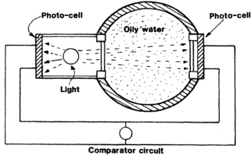
deposit on glass lenses. They are easily removed for cleaning. - Bilge or ballast water passing through a sample chamber can be monitored by a strong light shining directly through it and on to a photo-cell (Figure 1). Light reaching the cell decreases with increasing oil content of the water. The effect of this light on the photo-cell compared with that of direct light on the reference cell to the left of the bulb, can be registered on a meter calibrated to show oil content.
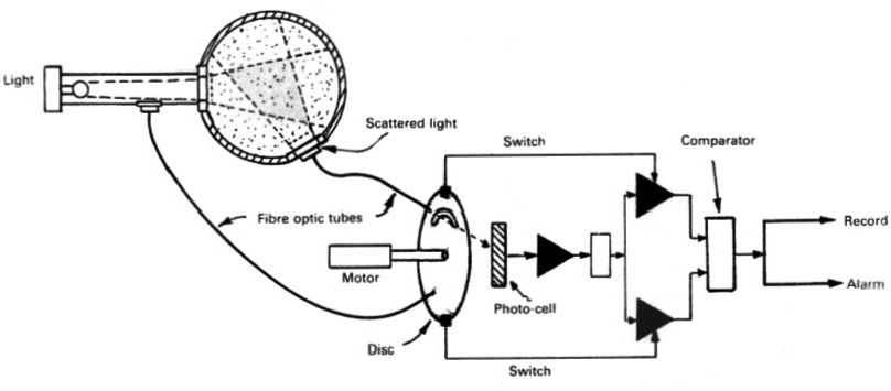
- Another approach is to register light scattered by oil particles dispersed in the water by the sampling pumps (Figure 2), Light reflected or scattered by any oil particles in the flow, illuminates the scattered light window. This light when compared with the source light increases to a maximum and then decreases with increasing oil content of the flow.
- Fibre optic tubes are used in the device shown to convey light from the source and from the scattered light window to the photo-cell. The motor-driven rotating disc with its slot, lets each light shine alternately on the photo-cell and also, by means of switches at the periphery, causes the signals to be passed independently to a comparator device, These two methods briefly described, could be used together to improve accuracy, but they will not distinguish between oil and other particles in the flow.
- Methods of checking for oil by chemical test would give better results but take too long in a situation where excess amounts require immediate shut down of the oily water separator.
Tanker ballast:-
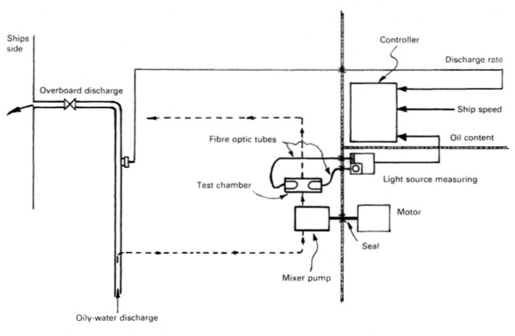
- Sampling and monitoring equipment fitted in the pump room of a tanker can be made safe by using fibre optics to transmit light to and from the sampling chamber (Figure 3). The light source and photo-cell can be situated in the cargo control room together with the control, recording and alarm console. The sampling pump can be fitted in the pump room to keep the sampling pipe short and so minimize time delay.
- For safety the drive motor is fitted in the machinery space, with the shaft passing through a gas-tight seal in the bulkhead. Oil content reading of the discharge is fed into the control computer together with discharge rate and ship’s speed to give a permanent record.
With reference to oil monitoring of bilge and tanker ballast discharges: State the Inputs that are recorded and output operation.
List of items to be recorded:- (Marpol Annex I)
(A) Ballasting or cleaning of oil fuel tanks
- Identity of tank(s) ballasted.
- Whether cleaned since they last contained oil and, if not, type of oil previously carried.
- Cleaning process:
- position of ship and time at the start and completion of cleaning;
- identify tank(s) in which one or another method has been employed (rinsing through, steaming, cleaning with chemicals; type and quantity of chemicals used, in cubic metres);
- identity of tank(s) into which cleaning water was transferred.
- Ballasting:
- position of ship and time at start and end of ballasting;
- quantity of ballast if tanks are not cleaned, in cubic metres.
(B) Discharge of dirty ballast or cleaning water from oil fuel tanks referred to under section (A)
- Identity of tank(s).
- Position of ship at start of discharge.
- Position of ship on completion of discharge.
- Ship’s speed(s) during discharge.
- Method of discharge:
- through 15 ppm equipment;
- to reception facilities.
- Quantity discharged, in cubic metres.
(C) Collection and disposal of oil residues (sludge and other residues)
- Collection of oil residues: Quantities of oil residues (sludge and other oil residues) retained on board. The quantity should be recorded weekly:* (This means that the quantity must be recorded once a week even if the voyage lasts more than one week)
- identity of tank(s) . . . . . . . . . . . . . . . . . . . . . . . . . . . . . .
- capacity of tank(s) . . . . . . . . . . . . . . . . . . . . . . . . . . . .m3
- total quantity of retention . . . . . . . . . . . . . . . . . . . . . . m3
- Methods of disposal of residue. State quantity of oil residues disposed of, the tank(s) emptied and the quantity of contents retained in cubic metres:
- to reception facilities (identify port);
- transferred to another (other) tank(s) (indicate tank(s) and the total content of tank(s));
- incinerated (indicate total time of operation);
- other method (state which).
(D) Non-automatic discharge overboard or disposal otherwise of bilge water which has accumulated in machinery spaces
- Quantity discharged or disposed of, in cubic metres.
- Time of discharge or disposal (start and stop).
- Method of discharge or disposal:
- through 15 ppm equipment (state position at start and end);
- to reception facilities (identify port);
- transfer to slop tank or holding tank (indicate tank(s); state quantity retained in tank(s), in cubic metres).
(E) Automatic discharge overboard or disposal otherwise of bilge water which has accumulated in machinery spaces:-
- Time and position of ship at which the system has been put into automatic mode of operation for discharge overboard, through 15 ppm equipment.
- Time when the system has been put into automatic mode of operation for transfer of bilge water to holding tank (identify tank).
- Time when the system has been put into manual operation.
