Q) Write short notes
on: Protection / Precautions against Crank Case Explosion.
Ans:-
Protection against Crankcase explosions:
Crankcase doors of sufficient strength are
provided so that they do not get displaced by crankcase explosion. They must be
fastened sufficiently.
One or more crankcase explosion relief doors
are fitted, depending on engine size. Crankcase explosion relief valves are
fitted with flame arrestors.
Crankcase oil mist detectors (OMD) and
monitoring equipment are provided. They give an alarm and also indicate the
unit where the mist level is high. Low level of mist is generally an alarm
only. But high level of mist gives an alarm / initiates slowdown of the main
engine. The OMD must be checked to see it is functional.
High bearing temperature alarms are provided.
Warning notices are provided on crankcase
doors indicating doors not to be opened immediately if overheating is
suspected.
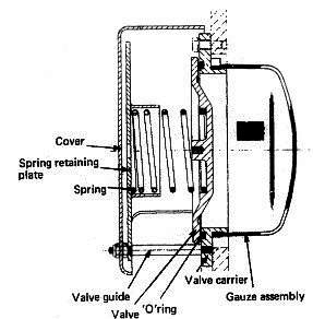
Crankcase Relief Door & Valve
The figure alongside shows a Crankcase explosion relief door & valve. It consists of:-
A woven wire gauze assembly that does not
allow flame to travel out of the crankcase.
A relief valve usually made of aluminum.
A spring against a retaining plate and
A discharge hood so designed that products of
explosion are discharged in such a way that it does not cause harm to the
engine room personnel.
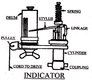
Q) Write short notes
on: Use of indicator card on board.
Ans:- Use of indicator card on board:
Power
Card is the measurement of the variation of pressures in a cycle.
Irregularities
in the shape of the diagram will show operational faults. Maximum or peak
pressure may be measured to scale between the atmospheric line and the highest
point on the diagram.
Compression
diagram is taken in a similar manner to the power card but with the fuel shut
off from the cylinder.
The
height of this curve shows maximum compression pressure. If compression and
expansion lines coincide, it shows that the indicator is correctly synchronized
with the engine.
Reduction
in height of this diagram show slow compression, which may be due to worn
cylinder liner, faulty piston rings, insufficient scavenge air or leaky exhaust
valve, any of the which will cause poor combustion.
Draw
card or out of phase diagram is taken in a similar manner to the power card, with
fuel pump engaged but with the indicator drum 90″C out of phase piston
stroke. This illustrates more clearly the pressure changes during fuel
combustion. Fuel timing or injector faults may be detected from its shape.
Light
or Weak spring diagram is again similar to the power card and in phase with the
engine, but taken with a light compression spring fitted to the indicator showing
pressure changes during exhaust and scavenge to an enlarged scale.
It
can be used to detect faults and scavenge to an enlarged scale. It can be used
to detect operations.
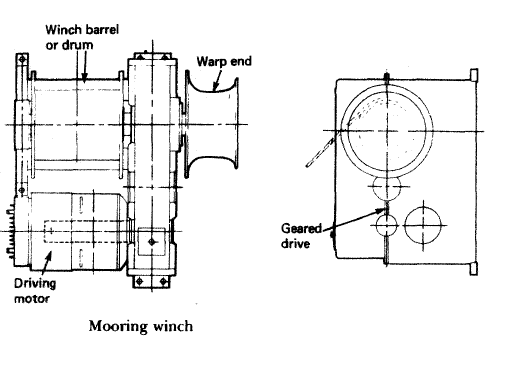
Purpose of Deck Mooring Winch and Windlass Winch used on board ship:
Deck Mooring Winch:-
Deck Mooring Winch
Mooring winch is a mechanical device used for securing a ship to the berth. An equipment with various barrels used for pulling ropes or cables, mooring winches play an important role in berthing the ship ashore.
The barrels, also known as winch drums, are used for hauling in or letting out the wires or ropes, which will help in fastening the ship to the berth.
Mooring winches assembly comes in various arrangements with different number of barrels, depending on the requirement of the ship.
The main parts of mooring winch includes a winch barrel or a drum, a warp end and a driving motor. Modern mooring winches comprises of elaborate designs with various gear assemblies, which can be electric, pneumatic or hydraulic driven.
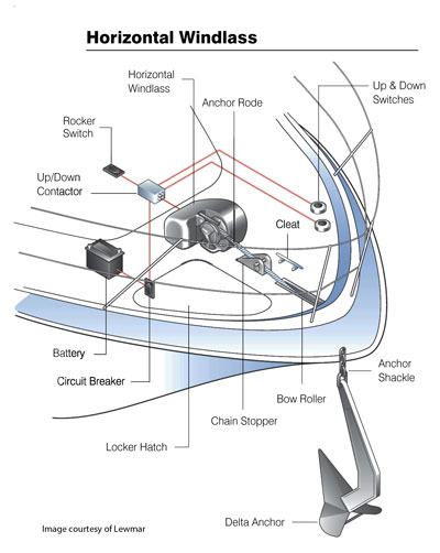
Windlass Winch:-
Windlass Winch
A windlass is a machine used
on ships that is used to let-out and heave-up equipment such as a ship’s anchor
or a fishing trawl. On some ships, it may be located in a specific room called
the windlass room.
An anchor windlass is a
machine that restrains and manipulates the anchor chain on a boat, allowing the
anchor to be raised and lowered by means of chain cable. A notched wheel
engages the links of the chain or the rope.
A trawl windlass is a
similar machine that restrains or manipulates the trawl on a commercial fishing
vessel. The trawl is a sort of big fishing net that is wound on the windlass.
The fishermen either let-out the trawl or heave-up the trawl during fishing
operations. A brake is provided for additional control. The windlass is usually
powered by an electric or hydraulic motor operating via a gear train.
Technically speaking, the
term “windlass” refers only to horizontal winches. Vertical designs
are correctly called capstans. Horizontal windlasses make use of an integral
gearbox and motor assembly, all typically located above-deck, with a horizontal
shaft through the unit and wheels for chain and/or rope on either side.
Vertical capstans use a vertical shaft, with the motor and gearbox situated
below the winch unit (usually below decks).
Q) List the routine
maintenances carried out on board.
Ans:- Efficient planning and
adequate usage of equipments is the key to productive maintenance.
Types of Maintenance Procedures:-
Preventive or Scheduled Maintenance System: – It is famously known as
the PMS or Planned Maintenance System. In this type of system the maintenance
is carried out as per the running hours like 4000 hrs, 8000 hrs etc., or by the
calendar intervals like 6 monthly, yearly etc. of the machinery. The
maintenance is carried out irrespective of the condition of the machinery. The
parts have to be replaced if it is written in the schedule, even if they can be
still used.
Corrective or Breakdown Maintenance: – In this system the maintenance is carried
out when the machinery breaks down. This is the reason it is known as the
breakdown maintenance. This is not a suitable and good method as situations may
occur wherein the machinery is required in emergency. The only advantage of
this system is that the working of machinery parts is used to its full life or
until it breaks. This system might get costly as during breakdown several other
parts may also get damaged.
Condition Maintenance system: – In this system the machinery parts are checked
regularly. With the help of sensors etc. the condition of the machinery is
accessed regularly and the maintenance is done accordingly. This system
requires experience and knowledge as wrong interpretation may damage the
machinery and lead to costly repairs which may not be acceptable by the
company.
Q) With reference to
oil monitoring of bilge and tanker ballast discharges: Describe with aid of a
sketch, the general arrangements of an oil monitoring system.
Ans:- Oil content monitoring – Working principles & procedure for ship service systems:-
In the past, an inspection
glass, fitted in the overboard discharge pipe of the oil/water separator
permitted sighting of the flow. The discharge was illuminated by a light bulb
fitted on the outside of the glass port opposite the viewer. The separator was
shut down if there was any evidence of oil carry over, but problems with
observation occurred due to poor light and accumulation of oily deposits on the
inside of the glasses.
Present-day monitors are
based on the same principle. However, whilst the eye can register anything from
an emulsion to globules of oil a light-sensitive photo-cell detector cannot.
Makers may therefore use a sampling and mixing pump to draw a representative
sample with a general opaqueness more easily registered by the simple
photo-cell monitor. Flow through the sampling chamber is made rapid to reduce
deposit on glass lenses. They are easily removed for cleaning.
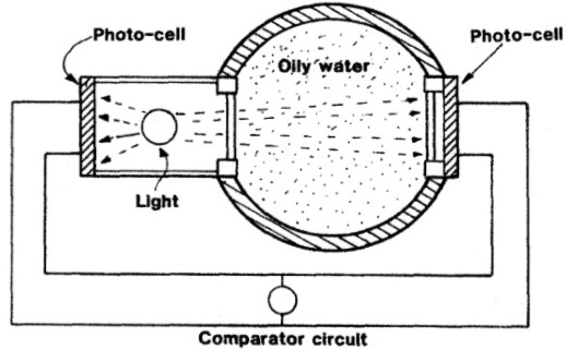
Bilge or ballast water
passing through a sample chamber can be monitored by a strong light shining
directly through it and on to a photo-cell (Figure 1). Light reaching the cell
decreases with increasing oil content of the water. The effect of this light on
the photo-cell compared with that of direct light on the reference cell to the
left of the bulb, can be registered on a meter calibrated to show oil content.
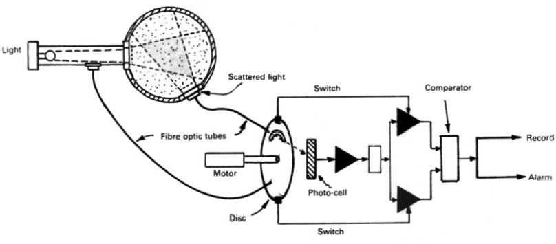
Another approach is to
register light scattered by oil particles dispersed in the water by the
sampling pumps (Figure 2), Light reflected or scattered by any oil particles in
the flow, illuminates the scattered light window. This light when compared with
the source light increases to a maximum and then decreases with increasing oil
content of the flow.
Fibre optic tubes are used
in the device shown to convey light from the source and from the scattered
light window to the photo-cell. The motor-driven rotating disc with its slot,
lets each light shine alternately on the photo-cell and also, by means of
switches at the periphery, causes the signals to be passed independently to a
comparator device, These two methods briefly described, could be used together
to improve accuracy, but they will not distinguish between oil and other
particles in the flow.
Methods of checking for oil
by chemical test would give better results but take too long in a situation
where excess amounts require immediate shut down of the oily water separator.
Monitor for oily water using direct light (Figure-1)
Monitor based on scattered light (courtesy Sofrance) (Figure-2)
Tanker ballast:-
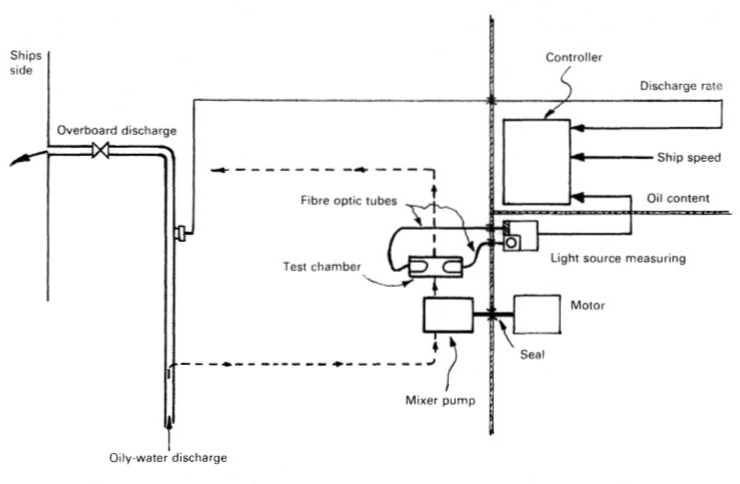
Sampling and monitoring
equipment fitted in the pump room of a tanker can be made safe by using fibre
optics to transmit light to and from the sampling chamber (Figure 3). The light
source and photo-cell can be situated in the cargo control room together with
the control, recording and alarm console. The sampling pump can be fitted in
the pump room to keep the sampling pipe short and so minimize time delay.
For safety the drive motor
is fitted in the machinery space, with the shaft passing through a gas-tight
seal in the bulkhead. Oil content reading of the discharge is fed into the
control computer together with discharge rate and ship’s speed to give a
permanent record.
Seris Monitoring System for Tanker Ballast (Figure-3)
Q) With reference to
oil monitoring of bilge and tanker ballast discharges: State the Inputs that
are recorded and output operation.
Ans:- List of items to be recorded:- (Marpol Annex I)
(A) Ballasting or cleaning of oil fuel tanks
Identity of tank(s) ballasted.
Whether cleaned since they last contained oil and, if not, type of oil previously carried.
Cleaning process:
position of ship and time at the start and completion of cleaning;
identify tank(s) in which one or another method has been employed (rinsing through, steaming, cleaning with chemicals; type and quantity of chemicals used, in cubic metres);
identity of tank(s) into which cleaning water was transferred.
Ballasting:
position of ship and time at start and end of ballasting;
quantity of ballast if tanks are not cleaned, in cubic metres.
(B) Discharge of dirty ballast or cleaning water from oil fuel tanks referred to under section (A)
Identity
of tank(s).
Position
of ship at start of discharge.
Position
of ship on completion of discharge.
Ship’s
speed(s) during discharge.
Method
of discharge:
through 15 ppm equipment;
to reception facilities.
Quantity
discharged, in cubic metres.
(C) Collection and disposal of oil residues (sludge and other residues)
Collection of oil residues: Quantities of oil residues (sludge and other oil residues) retained on board. The quantity should be recorded weekly:* (This means that the quantity must be recorded once a week even if the voyage lasts more than one week)
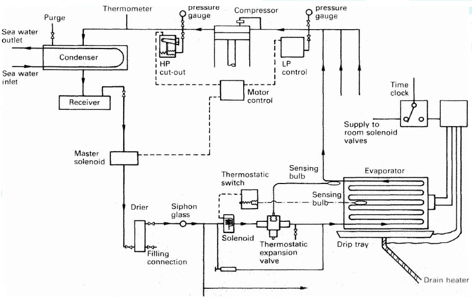
Q) For a fully
automatic provisions refrigeration system incorporating a number of rooms: Sketch
a line diagram detailing the devices incorporated into the refrigeration system
to protect the machinery and equipment against malfunction.
Main Components of Refrigeration Plants
Main Components of
Refrigeration plants:- Any refrigeration unit works with different components inline to each
other in series. The main components are:
Compressor: Reciprocating single or two stage compressor is commonly
used for compressing and supplying the refrigerant to the system.
Condenser: Shell and tube type condenser is used to cool down the
refrigerant in the system.
Receiver: The cooled refrigerant is supplied to the receiver, which is
also used to drain out the refrigerant from the system for maintenance purpose.
Drier: The drier connected in the system consists of silica gel to
remove any moisture from the refrigerant.
Solenoids: Different solenoid valves are used to control the flow of
refrigerant into the hold or room. Master solenoid is provided in the main line
and other solenoid is present in all individual cargo hold or rooms.
Expansion valve: An Expansion valve regulates the refrigerants to
maintain the correct hold or room temperature.
Evaporator unit: The evaporator unit acts as a heat exchanger to cool
down the hold or room area by transferring heat to the refrigerant.
Control unit: The control unit consist of different safety and operating
circuits for safe operation of the refer plant.
Compressor
safety devices: The compressor is protected by three safety switches:-
The OP switch or Oil Differential Pressure switch compares the measured
lubricating oil pressure to the Suction (crankcase) pressure. Should the
differential pressure fall below a pre-set minimum (about 1.2 bar) then the
compressor will trip and require a manual reset to restart. A time delay is
built into the circuit to allow sufficient time for the lubricating oil
pressure to build up when starting before arming the circuit.
The HP or High Pressure switch, is fitted to the outlet of the compressor
before the isolating valve. On over pressurization (dependent on the
refrigerant, up to about 24bar bar for R22) the switch will trip the compressor
and a manual reset is required before restart.
The LP or Low Pressure switch when activated (at about 1 bar for R22)
will trip the compressor and require a manual reset before the compressor can
be restarted.
This normally takes the form
of an LP cut out pressure switch with automatic reset on pressure rise. The cut
out set point is just above the LP trip point says at about 1.4bar.
An adjustable differential
is set to about 1.4bar to give a cut in pressure of around 2.8 bar. The
electrical circuit is so arranged that even when the switch has reset, if no
room solenoid valves are open the compressor will not start. This is to prevent
the compressor cycling due to a leaky solenoid valve.
In addition to this extra LP
switches may be fitted which operate between the extremes of the LP cut in and
cut out to operate compressor unloaders.
Some modern systems contain
a rotary vane compressor with variable speed (frequency changing) control.
Q) For a fully automatic provisions refrigeration system incorporating a number of rooms: Explain how critical temperature restricts plant operation and how these limitations overcome?
Ans:- The Critical Point:- The critical point is the point above which:
The gas will not liquefy by the action of pressure alone. This is an
important temperature for refrigeration systems which rely on the change of
state for heat transfer.
The gas will not liquefy by cooling alone.
Working of Ship’s Refrigeration Plant:-
The compressor acting as a circulation pump for refrigerant has two safety cut-outs- Low pressure (LP) and High Pressure (HP) cut outs.
When the pressure on the suction side drops below the set valve, the control unit stops the compressor and when the pressure on the discharge side shoots up, the compressor trips.
LP or low pressure cut out is controlled automatically i.e. when the suction pressure drops, the compressor stops and when the suction pressure rises again, the control system starts the compressor. HP or high pressure cut out is provided with manually re-set.
The hot compressed liquid is passed to a receiver through a condenser to cool it down. The receiver can be used to collect the refrigerant when any major repair work has to be performed.
The master solenoid is fitted after the receiver, which is controlled by the control unit. In case of sudden stoppage of compressor, the master solenoid also closes, avoiding the flooding of evaporator with refrigerant liquid.
The room or hold solenoid and thermostatic valve regulate the flow of the refrigerant in to the room to maintain the temperature of the room.
For this, the expansion valve is controlled by a diaphragm movement due to the pressure variation which is operated by the bulb sensor filled with expandable fluid fitted at the evaporator outlet.
The thermostatic expansion valve supplies the correct amount of refrigerants to evaporators where the refrigerants takes up the heat from the room and boils off into vapours resulting in temperature drop for that room.
This is how temperature is maintained in the refrigeration plant of the ship.
A safety system includes alarm, cut offs, and trips which safeguards the machinery and its parts from getting damage.
Q) For a fully
automatic provisions refrigeration system incorporating a number of rooms: What
is the effect on the environment of the release of refrigerants into the
atmosphere?
Ans:- Environmental and
Safety properties of Refrigerants:- At present the environment friendliness
of the refrigerant is a major factor in deciding the usefulness of a particular
refrigerant. The important environmental and safety properties are:
Ozone Depletion Potential (ODP): According to the Montreal protocol, the ODP of refrigerants should be zero, i.e., they should be non-ozone depleting substances.
Global Warming Potential (GWP): Refrigerants should have as low a GWP value as possible to minimize the problem of global warming. Refrigerants with zero ODP but a high value of GWP (e.g. R134a) are likely to be regulated in future.
Total Equivalent Warming Index (TEWI): The factor TEWI considers both direct (due to release into atmosphere) and indirect (through energy consumption) contributions of refrigerants to global warming. Naturally, refrigerants with as a low a value of TEWI are preferable from global warming point of view.
Toxicity: Ideally, refrigerants used in a refrigeration system should be non-toxic. Toxicity is a relative term, which becomes meaningful only when the degree of concentration and time of exposure required to produce harmful effects are specified. In general the degree of hazard depends on:
Amount of refrigerant used vs total space
Type of occupancy
Presence of open flames
Odor of refrigerant, and
Maintenance condition
Flammability: The refrigerants should preferably be nonflammable and non-explosive. For flammable refrigerants special precautions should be taken to avoid accidents.
Chemical stability: The refrigerants should be chemically stable as long as they are inside the refrigeration system.
Compatibility with common materials of construction (both metals and non-metals)
Miscibility with lubricating oils: Oil separators have to be used if the refrigerant is not miscible with lubricating oil (e.g. ammonia). Refrigerants that are completely miscible with oils are easier to handle (R12).
Q) Explain how paralleling of generator’s carried out.
Ans:- Parallel Operation of Generators:-
Depending upon the capacity
and the electrical load, more than one alternator can be connected to the
common Bus bars. The connecting process is called ‘Synchronising’ i.e. enabling
the parallel operation of the alternators.
Following conditions must be
fulfilled for paralleling the Alternators:
Voltage must be same.
Frequency must match.
Phase sequence must be correct.
In short, the incoming
alternator should have the same parameters as the running alternator(s). If the
speed of the incoming machine is different, the ‘governor control switch’
should be used to adjust the speed.
Departure from the above
conditions will result in the formation of power surges and unwanted
electro-mechanical oscillation of rotor which will damage the equipment.
To carry out the paralleling
operation, following devices are provided:
Synchroscope
Lamps (Dark/Bright)
Following are the steps to
carry out with paralleling using a synchroscope:
Check voltages are same.
Check frequency of incoming generator is same as running generator.
Put on synchroscope and see that pointer turns slowly in clockwise
direction (may require to adjust speed of incoming generator using the
‘governor control switch’ for this).
When the pointer is at 11 o’clock position, close the breaker of
incoming generator.
Now the load is equally distributed among the generators.
Advantages of Parallel
Operating Alternators
For maintenance or inspection, one machine can be taken out from
service and the other alternator can keep up for the continuity of supply.
Load supply can be increased.
During light loads, more than one alternator can be shut down while the
other will operate in nearly full load.
High efficiency and operating cost is reduced.
Ensures the protection of supply and enables cost-effective generation.
Q) Sketch and describe a Typical Ships Electrical Distribution System.
Typical Ships Electrical Distribution System
The electrical power
distribution system on board a ship is designed so as to provide a secure
supply to all loads with adequate built in protection for the equipment and
operating personnel. The general scheme of a ship’s electrical power system is
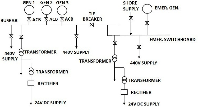
common to nearly all ships.
Both the auxiliary and
emergency services are supplied by the Main generators during normal operating
conditions. In event of emergency, only the emergency services are supplied by
the Emergency generator.
The below figure shows a
typical electrical distribution system of a vessel.
The main generators are
connected to the main bus bar via air circuit breakers. The main bus bar
supplies 440V directly, 220V via transformers and 24V DC via transformers and
rectifiers.
The main bus bar is
connected to the emergency switch board via the tiebreaker. Emergency generator
is also connected to the emergency switch board.
Arrangements are also made
for shore supply to be connected.
Q) State some built in measures by which steering gear mechanism can be kept operational in the event of breakage of rudder actuator, pipe failures, motor burn out etc.
Ans:- Measures against steering gear failure: Some general requirements for steering gears, based on the various regulations and SOLAS 1974, are given below:
Ships must have a main and an auxiliary steering gear, arranged so that the failure of one does not render the other inoperative. An auxiliary steering gear need not be fitted, however, when the main steering gear has two or more identical power units and is arranged such that after a single failure in its piping system or one of its power units, steering capability can be maintained. To meet this latter alternative the steering gear has to comply with the operating conditions of paragraph 2 — in the case of passenger ships while any one of the power units is out of operation. In the case of large tankers, chemical tankers and gas carriers the provision of two or more identical power units for the main steering gear is mandatory.
The main steering gear must be able to steer the ship at maximum ahead service speed and be capable at this speed, and at the ship’s deepest service draught, of putting the rudder from 35 deg on one side to 30 deg on the other side in not more than 28 secs. (The apparent anomaly in the degree of movement is to allow for difficulty in judging when the final position is reached due to feedback from the hunting gear which shortens the variable delivery pump stroke.) Where the rudder stock, excluding ice strengthening allowance, is required to be 120 mm diameter at the tiller, the steering gear has to be power operated.
The auxiliary steering gear must be capable of being brought speedily into operation and be able to put the rudder over from 15deg on one side to 15deg on the other side in not more than 60 sees with the ship at its deepest service draught and running ahead at the greater of one half of the maximum service speed or 7 knots. Where the rudder stock (excluding ice strengthening allowance) is over 230 mm diameter at the tiller, then the gear has to be power operated.
It must be possible to bring into operation main and auxiliary steering gear power units from the navigating bridge. A power failure to any one of the steering gear power units or to its control system must result in an audible and visual alarm on the navigating bridge and the power units must be arranged to restart automatically when power is restored.
Steering gear control must be provided both on the bridge and in the steering gear room for the main steering gear and, where the main steering gear comprises two or more identical power units there must be two independent control systems both operable from the bridge (this does not mean that two steering-wheels are required). When a hydraulic tele-motor is used for the control system, a second independent system need not be fitted except in the case of a tanker, chemical carrier or gas carrier of 10000 gt and over. Auxiliary steering gear control must be arranged in the steering gear room and where the auxiliary gear is power operated, control must also be arranged from the bridge and be independent of the main steering gear control system. It must be possible, from within the steering gear room, to disconnect any control system operable from the bridge from the steering gear it serves. It must be possible to bring the system into operation from the bridge.
Hydraulic power systems must be provided with arrangements to maintain the cleanliness of the hydraulic fluid. A low level alarm must be fitted on each hydraulic fluid reservoir to give an early audible and visual indication on the bridge and in the engine room of any hydraulic fluid leakage. Power operated steering gears require a storage tank arranged so that the hydraulic systems can be readily re-charged from a position within the steering gear compartment. The tank must be of sufficient capacity to recharge at least one power actuating system.
Where the rudder stock is required to be over 230 rnm diameter at the tiller (excluding ice strengthening) an alternative power supply capable of providing power to operate the rudder, as described in paragraph 3 above, is to be provided automatically within 45 seconds. This must supply the power unit, its control system and the rudder angle indicator and can be provided from the ships emergency power supply or from an independent source of power located within the steering compartment and dedicated for this purpose. Its capacity shall be at least 30 minutes for ships of 1O,OOO gt and over and 10 minutes for other ships.
Q) Sketch &
describe the Reverse Osmosis system for the production of drinking water on
board the ships.
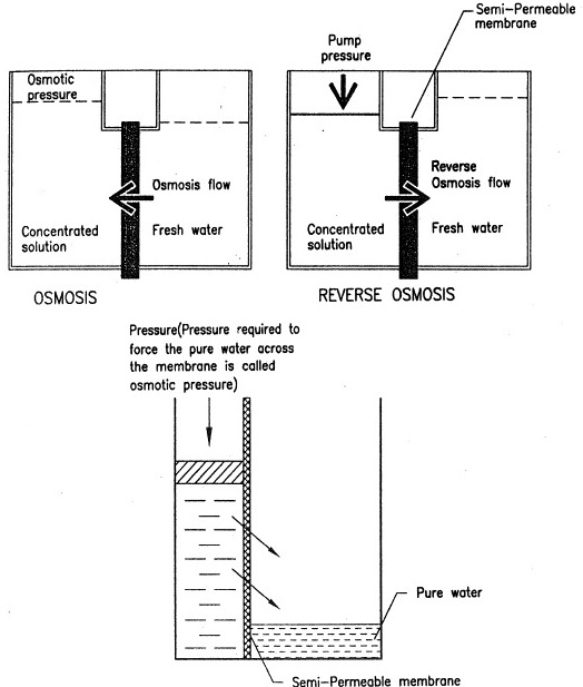
Principle of Reverse Osmosis – (Figure-1)
Reverse Osmosis:-
One of the methods of
producing fresh water is by using the principle of Osmosis. Osmosis term is
used to describe passage of pure water from one side off a semi-permeable
membrane into a salt or other solution on the other, with the result the salt
solution is diluted but the water remains pure.
Reverse Osmosis is a water
filtration process, which makes use of semi-membrane materials. Salt water on
one side of the membrane is pressurized by a pump and forced against the
material. Pure water passes through but not thee salts see figure 1.
Pressure required to force
the pure water through, is called osmotic pressure & requirement of osmotic
pressure is higher if the salinity of salt water is higher. For production of
large amounts of pure water, the membrane area must be large and it must be
tough enough to withstand the pump pressure.
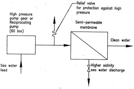
Also, as continuous supply
of sea water is used as feed, the salinity of feed is steady, than the osmotic
pressure required to force fresh water through is also steady, and steady
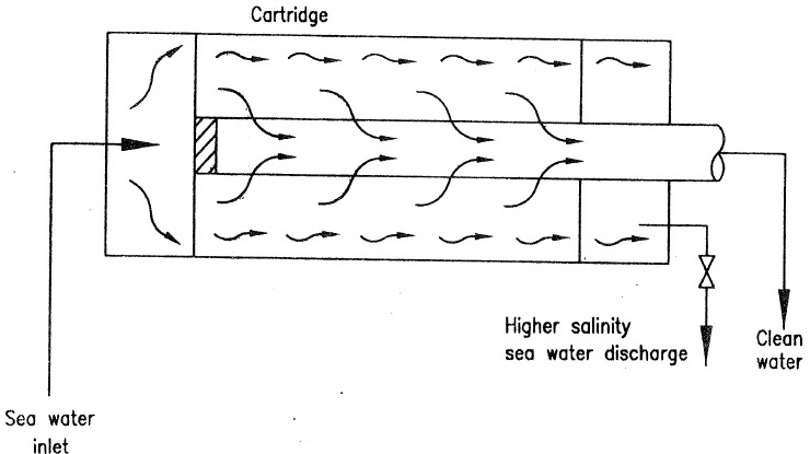
pressure is taken from a continuously running pump, see figure 2. Semi
permeable membrane may be provided by a bunch off cartridge as shown in figure
3.
Reverse Osmosis System for continuous supply of Fresh Water (Figure -2)
Cartridge used for Reverse Osmosis (Figure -3)
Q) State –
Pre-treatment used with RO equipment.
Ans:- Due to the low
temperature of operation in low pressure evaporators, the fresh water produced
by such a FWG may be harmful to drink as it may contain bacteria. It may not
even contain the minerals that are needed. Therefore, it needs to be treated,
in order for it to be potable. The treatment of fresh water can be done using
the following methods:
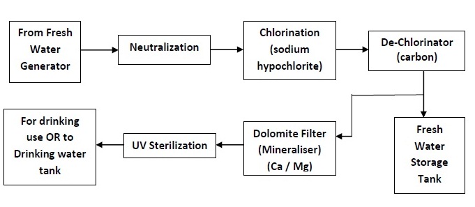
Chlorine Sterilization: The sterilization by
chlorine is recommended and it may be done by an excess dose of chlorine
provides by sodium hypochlorite in a liquid form or by adding calcium chloride
granules. The chlorine content may be upto 0.2 ppm, for it to be effective. The
water is then de-chlorinated in a bed of activated carbon to remove the excess
chlorine. Any colour, taste and odour, which were present in the water, will
also be removed by the carbon.
Silver Ion Sterilization: In this method, silver
ions are injected into the distillate, by means of a silver anode. This method
of sterilization is effective since silver is toxic to the bacteria present in
the water. Unlike chlorine, the silver ions do not evaporate. The amount of
silver ion released into the water is controlled by the current and the silver
ion content may be upto 0.08 ppm, for it to be effective.
Ultraviolet Light
Sterilization:
A temporary but immediately effective sterilization is by means of UV light.
Chlorine and silver ion methods although long lasting, change the taste of the
water and require efficient carbon filtration to remove the odour. UV light on
the other hand does not cause any physical or chemical change in the water.
This method uses UV lamps to produce short wave radiations that destroy the
bacteria, viruses and other organisms in the water. This method is usually used
on the discharge side of the water storage tank so that the water is sterilized
immediately before use.
Sterilization by Ozone: Use of ozone for
sterilization is very effective. It is an effective oxidant. However, the
equipment is costly and has high running cost.
An example of treatment of fresh water produced by the FWG is shown in the flowchart below. The system may be different on different ships. The end result should however be that the produced water made available for drinking is slightly alkaline, sterilized, clear and good in taste.
Flow chart of pre-treatment of Drinking Water
Q) State – The
Post-treatment necessary.
The Permeate (product water) from the above process may contain small quantities of dissolved salts and is suitable as drinking water if the salt content is below 250 ppm, well within the WHO limit.
However, if the water is to be used for boiler feed, it has to be completely free from salts and the product water may require further treatment to get rid of small quantities of salts by Ion Exchange Treatment.
Q) Explain why
regular testing of water in Auxiliary Boilers is desirable.
Ans:- Boiler water tests are
tests to find a particular chemical compound or excess chemical compound in the
boiler water. If you do the boiler water test correctly and regularly you can
find excess compound or impurities in the boiler water and prevent following
factors:-
Prevent corrosion in the
boiler feed system by maintaining the boiler water’s alkaline condition.
Prevent scale formation in
the boiler tubes.
Remove dissolved gases such
as oxygen from water.
Control sludge formations
which prevent carry over with the steam.
Determine the amount of
impurities by which we can select appropriate treatment.
Exercise careful control
over boiler treatment chemicals.
Maintain and provide
residual reserve of chemicals.
Improve efficiency, thus
increasing boiler life and service period of boilers.
For economical operation of
boiler.
Q) For each test normally carried out, state – Reasons for making the test.
Ans: – Different Boiler Water
Tests and its Purpose:
Hydrate Alkalinity – For
testing the presence of hydrates.
Condensate PH – Measuring
the acidity or alkalinity of the water.
Chloride ppm CI Test-
measure the chlorine content or sea water presents.
Phosphate – For testing the
presence of phosphate compounds. It is important to maintain minimum of 10 ppm
of phosphate.
Deha/Oxygen test – For
testing oxygen and Chemical content.
Neutralized Conductivity –
For testing the presence of ferrous ions and metal contents.
Feed Water Hardness – For
testing the presence of carbonate compounds.
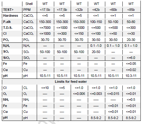
Q) For each test normally carried out, state – Acceptable values for any particular type of auxiliary boiler.
Acceptable values for any particular type of auxiliary boiler
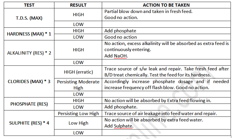
Q) Action required
when measured values differ appreciably from desired values.
Ans:- When measured values differ from acceptable standards, a corrective action chart is to be referred and suitable action taken accordingly. This chart is reproduced:-
Action required when measured values differ appreciably from desired values