Working of a Ship’s Auto Pilot with Sketch:
- An auto pilot is the ship’s steering controller which automatically manipulates the rudder to decrease the error between the reference heading and actual heading.
- Autopilot relieves the helmsman to great extent but definitely autopilot is not a substitute for helmsman.
- Autopilot also reduces fuel consumption as the zig-zag course is avoided.
Working of Auto Pilot:-
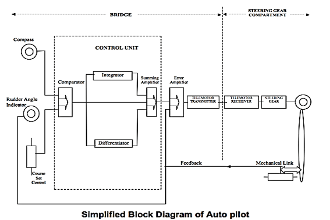
- Course is selected by the course selector.
- Present heading is indicated by the compass.
- The output from the compass is fed to the comparator in the control unit. The signal from the course selector is also fed to the comparator.
- Difference between the two signals is causing the output error signal detected by the comparator.
- Integrator and differentiator also analyze the signal.
- The signals from the comparator, integrator and differentiator are fed to summing amplifier (control unit).
- The summing amplifier in turn, passes the signals to error amplifier which also receives feedback from the steering gear.
- The output of error amplifier is transmitted to steering gear via telemotor transmitter and telemotor receiver.
- A torque motor may be fitted instead of a telemotor.
Controls available in Auto Pilot console:
The Autopilot Control Unit – The PID Control Unit:- In order to maintain the ship’s course accurately, the deviation signal has to be generated under the following conditions:
- When the set course is changed (by the navigator).
- When the ship deviates from the set course (due to external factors).
For this purpose, the helm must be provided with data regarding the ship’s movement relative to the course to steer line.
This is achieved by electronic circuits with the help of the following:
- Proportional control
- Derivative control
- Integral control
Proportional Control:-
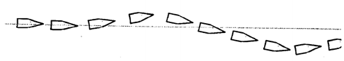
- The effect on steering, when only the proportional control is applied, causes the rudder to move by an amount proportional to the off-course error from the course to steer.
- When the ship has gone off-course to port, an error occurs and helm, proportional to the deviation and hence error signal, is used to bring her back to the set course.
- As the ship starts to return to the set course, the helm is gradually eased and finally removed when the ship is back on the set course.
- The rudder will be amidships when the ship reaches its set course and then the heading overshoots resulting in the vessel to go more to starboard. Correcting helm is now applied causing the ship to return to port and back to the original course.
- The vessel thus keeps on oscillating to port and starboard of the course line.
Derivative Control:-
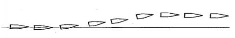
- In derivative control, the rudder is shifted by an amount proportional to the rate of change of the ship’s deviation from the course. Any deviation of course to port will cause correcting rudder to be applied to starboard.
- As the rate of change of course decreases, the automatic rudder control decreases and at a point X, the rudder will return to midships before the vessel reaches its set course.
- The ship will now make good a course parallel to the required course.
Integral Control:-
- Certain errors due to the design of the ship (bow going to port due to transverse thrust, shape of the hull, current draft, etc.) have an impact on the steering capabilities of the ship and have to be corrected for effective overall steering performance.
- In order to achieve this, signals are produced by sensing the heading error over a period of time and applying an appropriate degree of permanent helm. The rudder used to correct the course will now be about this permanent helm. That is, the permanent helm will now act as midships.
- Additionally, there are various controls provided on the autopilot system along with a filter system for the action of the winds and waves which supply more data to the autopilot which optimizes the performance of integral control.
- The output of these three controls is combined and the net resultant thus obtained drives the rudder maintaining the ship on the set course. This type of auto pilot is referred to as PID auto pilot.
Working of “Weather Control” in Auto Pilot System:
Rough weather and hostile sea conditions have adverse effects on the performance of the auto-pilot. Uncontrolled yawing of the ship can result in excessive rudder movement. Modern auto-pilot system has Weather control option in which the system automatically adjusts the setting to adapt to the changing weather and sea conditions. It also provides an option for the user to manual set a specific value.
Working of “Yaw Control” in Auto Pilot System:
The setting of the Yaw Control depends upon the wind and weather condition and their effect on the course keeping ability of the ship, in bad weather this setting should be set high and calm weather this should be set low. If Yaw Control is not set properly, the steering gear will over work & there will be excessive load on the system.
Working of “Off Course Alarm” in Auto Pilot System:
Off Course Alarm:- Usually an Off Course Alarm is fitted on the Autopilot. This can be set for the required amount of degrees. So that if at anytime the difference between the actual course and the Autopilot set course is more than the preset degrees, an alarm will warn the officer.
There is however, one limitation which should be noted. In case, the gyro compass itself begins to wander the Autopilot well steer so as to follow the wandering compass and the Off Course Alarm will not sound. It does not ring unless the difference between the course setting and gyro heading is more than the preset limit.
Working of “Rudder Limit” in Auto Pilot System:
Rudder Limit:- This setting specifies the maximum amount of rudder to be used when correcting the ship’s head or when altering course on autopilot. That is, if a setting of 10O is applied for rudder limit, when altering course the rudder will move to a maximum of 10O. This limit can be varied according to the requirements of the navigator.
Purpose of following settings in Autopilot: Rudder
- This control determines the amount of rudder to be used to correct the slightest amount deviation from the set course.
- The higher is setting the larger the rudder angle is used to correct a course deviation and this may result in over correcting.
- But if setting is less, the rudder angle is used to correct deviation may not be sufficient and will take longer time to return to set course.
- This is proportional controller which transmits a signal which is proportional to course error
- Controller output = constant (Kp) x Deviation
- The ratio can be changed by settings (i.e. the ratio between instantaneous heading error and rudder command) also called rudder multiplier.
- Control Knob alters the ratio of output.
- Higher setting – Larger rudder angle (results in overcorrecting – overshooting)
- Lower setting – Less rudder angle (Long time to return to set Co-Sluggish).
- Therefore, optimum setting required.
Purpose of following settings in Autopilot: Counter Rudder
- This control determines the amount of counter action by the rudder to be used to steady the ship on the set course keeping the overshoot to minimum.
- Too low setting will allow the ship to overshoot and too high setting will bring the ship back in long time.
- This is Derivative control.
- Purpose is to apply a relatively greater amount of helm at the beginning of a course alteration to get the ship turning. Once the ship is turning, just enough helm is applied in order to keep her coming around. When new heading is approached, opposite helm is applied to stop the swing. As the ship settles on new heading and the yaw rate disappears, the helm is removed.
- Produces an output when course of vessel is changing.
- Depends on rate of change of course:
- Controller output = constant ( KD ) x change of error / time
- Determines amount of counter rudder to steady the ship on set course.
- Keeps over shoot to minimum.
- Greater the ship’s inertia, greater the setting required. If ship has good dynamic stability, relatively small settings of counter rudder will be sufficient. If the ship is unstable, higher settings will be required.
- Depends on ship’s characteristics, loaded/ballast conditions and rate of turn.
- Too high setting will bring the ship to set Co slowly.
- Too low setting allows overshoot.
- As counter rudder settings increase, counter rudder increases.
- KD – Counter rudder time constant (Calibration done at sea trial to set KD).
Purpose of following settings in Autopilot: Constant Helm
Constant / Permanent Helm:
- This is integral controller. (In NFU this control is out of action).
- When ship has known imbalance to one side, requiring a certain amount of bias helm (e.g. TT of propeller) manual setting of the approximate bias speed up the effect of the AUTOMATIC PERMANENT HELM calculator, because it started off nearer to its target.
- Whether the control setting is estimated correctly or left at zero has no effect on the final steering accuracy but only in the time it takes to reach this heading accuracy.
- If not used as described above , the permanent helm should be left at ZERO and the automatic permanent helm will function normally.
- Produces output as long a course error persists.
- Used when beam winds; couple formed causing ship to turn into wind.
- Rudder position required to counteract is permanent helm.
- Continuous control calibrated from 20 (P) to 20 (S).


Purpose of following settings in Autopilot: Weather
The setting of the yaw control depends upon the wind and weather condition and their effect on course keeping ability of the ship in bad weather this setting should be set high and calm weather this should be low.
Purpose of following settings in Autopilot: Rudder Limit
Rudder limit: This control specifies the maximum amount of rudder to be used, when correcting the ship’s head or altering the ship’s course.
Auto Pilot should not be used in the following conditions:
- In narrow channels.
- At slow speeds.
- During manoeuvring.
- During pilotage.
- During heavy weather conditions.
- During large alteration of course.
- Near or in area of restricted visibility.
- When passing close to vessels etc.