Cellular Container Vessel:
A cellular vessel is a container ship specially designed for the efficient storage of freight containers one on top of other with vertical bracings at the four corners. The majority of vessels operated by maritime carriers are fully cellular ships.
Before 1991 most containerships where constructed with hatch covers. Because of the longer load and unloading times of these types of ships the cellular type was invented. As loading and unloading occurs only vertically and the containers have standardized dimensions (TEU), large quantities of cargo can quickly be loaded using gantry cranes.
Advantages:
- The cargo handling is more efficient resulting in shorter time in port
- Guide rails hold the containers into place instead of time consuming lashings
- No need of hatch covers, reducing maintenance, weight, and handling
- There is a high freeboard resulting in a stronger construction
- Containers lashed to cellular vessels are less vulnerable to crew tampering than containers on mixed-use cargo vessels, making them less of a risk from the standpoint of port security.
Disadvantages:
- The high freeboard results in higher registered tonnage.
- The price of the ship is high due to the amount of steel used and the complex design process.
- The absence of hatch covers means that rain water and overcoming seawater can freely enter into the cargo hold. Therefore, higher requirements of bilge systems are applicable to open cargo holds.
Bay Plan of a Cellular Container Vessel:
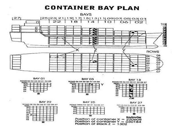
Information provided in Bay Plan of a Container System:-
- Each slot for a container is given a number which indicates its position on ship. The number consists of six digits the front “two digits” indicate the bay, the second “two digits” indicate the row and last “two Digits” indicate the tier.
- Bays – Numbered from fwd to aft. In 20 feet lengths commencing from fwd as 01, 03, 05, 07 and so on. A 40 feet container which occupies two bays is allotted an even number which is between the two 20 feet bays, it occupies. Thus, if a 40 feet container is stowed within bays 21 & 23 its bay number will be 22.
- Rows – Indicate the athwartship position of the container. If a slot is located on the C/L of the ship it is given a row 00. The starboard rows are numbered 01, 03, 05, 07 and so on commencing from the centre towards the shipside ad the port side slots are numbered 02, 04, 06, 08 etc. All the bays may not have a centre slot in which case there will not be a 00 row for that bay.
- Tiers – Indicate the height of the container. They are numbered 02, 04, 06, 08 etc. commencing from bottom. The tiers on deck are numbered 82, 84, 86, etc. starting from first tier on deck upwards.
A Bay Plan of the vessel will have diagrams of all bays showing the rows & Tiers inn each bay. The slots will not be numbered as each slot can be easily identified as per the numbering system described above, instead the container number is inserted. So that precise location of each container onboard can be identified and conversely the identity of each container in any slot can be known.
Cellular Container Ships: Anti-Heeling Tanks:
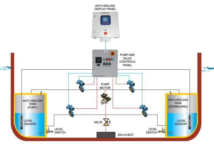
Anti – Heeling System:
The anti heeling system of a ship automatically detects the heeling angle of the ship and compensates the same. This allows the vessels to have continues loading and unloading cargo operation without stopping in between for list correction. This saves considerable amount time on the port.
In this system, ballast tanks are internally connected to each other by means of pipe lines, automatic valves and control systems. When the ship heels to any of the sides, the heeling sensor sends the signal for change of ships angle with respect to the ship’s upright position to the master control panel. This change in heeling angle is compensated by methods of auto transferring the water from the heeled side to the other side of the ship, making the vessel upright.
Level control switches are also installed in the ballast tank involved with the anti-heeling system to avoid low level or over filling and hence over pressurising of the tanks.
Types of Anti Heeling System:-
There are two widely used anti heeling system on board ships:
1) Pneumatic system:
This system comprises of air purging arrangement and regulating valve system to force the air on the top of ballast tank. The air is forced on one tank and purged from the other, making the water rapidly flow from pressurised to purged tank. This transfer of water is used to upright the vessel in quick time.
2) Water pump system:
The pump system consists of electrical motor driven water pump, which can be a reversible or non reversible pump, connected with remote controlled valves that can direct ballast water flow in between the tanks.
Advantages of Anti Heeling System:
- Allows safer and rapid cargo loading and unloading.
- Shortens harbour time and saves port dues.
- Reduces damage to ramp, rolling cargo and containers.
- Ensures safety of the ship and personals.
Torsional Stresses:
- Torsional stresses arise when the ship is evenly loaded along the fore & aft line. Although the ship may be upright overall, yet some bays may be excessively loaded on the port side, others on stbd side, giving rise to torsional stresses which tend to twist the ship along the centerline.
- At sea, these forces increase due to the effect of sea & swell.
- In container ships the beam, length and freeboard is large and there is uneven distribution of cargo as well.
- The torsional moments at the bay can be reduced by the use of ballast in the tanks at that bay.
- The torsional stresss will not reduce by correcting the imbalance at another bay.
- Torsional moments on each side = stack weight X distance from the centreline.
- The difference between prot and stbd moments gives the torsion at that point.
- The torsional stress at any point is the sum of torsion at all points before that line.
Stack Weight or Stack Load:
- Is the maximum weight that can be borne by the deck, hatch covers or tank top at the corners of a bottom slot near the cell guides.
- The weight of the container is distributed over the 4 corner fittings and not over the entire area occupied by the container. As such the point loads under the corners are very high.
- The internal structure of the vessel distributes this load over the strength members of the hull.
- The stack weights should not be exceeded during loading.
- Excessive stack weights can be avoided by allotting a mix of heavy and light containers to a stack.
Tare Weight:
Tare Weight – It is the weight of the container and/or packed materials without considering the weight of the goods inside the container.
Custom Plate on a Container:
The Customs plate (referring to the Customs Convention for Containers (CCC) requirements) showing the certificate applicable to the container to allow transport under customs seal.
Procedures for Loading & Carriage of Refrigerated Containers:
Reception and Loading/ Stowage of Cargo:
- Local port regulations should be known to ship’s officers with respect to opening and closing of compartments and accepted working temperatures for stevedores to avoid friction with them and delay to the ship.
- Cargo Carrying Instructions: – The cargo carrying instructions must be onboard before loading starts. They must be read and understood, and signed only if they are fully understood and the ship can comply with the instructions. The instructions have to be claused and questions asked if the ship cannot fulfil any of the instructions.
- The temperatures in the empty decks at the hatch opening before the loading starts, are to be noted as well as the temperatures on delivery and return air at the closing of the hatch when loading is finished.
- The hour when loading started and finished in each deck is also to be noted and this information is to be entered in the refrigeration report.
- Checkpoint Vessel-In:- The cargo is transported from the terminal to the quay. Before the cargo leaves the terminal, it passes through Checkpoint Terminal-Out. Checkpoint Vessel-In is defined as `In the vessel after all handling by the stevedores to the final stow in the hold’. At this point, the responsibility for the cargo is handed over from the stevedores/terminal to the ship. This is a very important stage, since from this point onwards the ship is responsible for the quality and quantity of the cargo.
- Checking the Cargo
- To check the cargo quantity, the ship’s staff have to tally the number of items being loaded onto the ship. Sometimes, private tally clerks are employed to assist them. Common sense is often the best tool to judge the cargo condition.
- Cargo quality is checked using the AC/DC criteria below:
- AC – apparent good order and condition. This implies reasonable checking of the cargo by sight and odour. There is no abnormal odour or visual fault (such as mould) and the pallet construction is sound and fit for sea transport
- DC – damaged condition. The cargo appears to be damaged.
- Walking boards should be used at all times if walking on cargo is necessary, particularly during pre-slung operations in the hatch square pre-slung cargo must be loaded with an adequate pallet spreader and handled without causing any damage slip sheets must be used pallets with display cartons, trays or bins are not to be used for pre-slung operations and should not be stowed in the hatch-square.
At the loading of cargo into a reefer vessel it is very essential that the quality of the cargo is checked. Utmost care should be taken to inspect the incoming cargoes for inherent damage. This can be done by taking random samples.
The appearance of the delivered cargo is to be supervised during the whole loading and pulp temperatures have to be taken regularly to get a full knowledge of the state of the cargo that is loaded. All bad conditions as well as the temperatures should be carefully noted. Any overripe or damaged cargo must be rejected and at times pre-cooled cargo with high pulp temperatures may be rejected.
Normally the highest and lowest pulp temperatures in each deck are to be inserted in the refrigeration report. Additionally pulp temperatures of cargoes to be maintained.
Remarks must be made on the mate’s receipts and in bills of lading unless other measures are agreed with Owners.
When loading a lower hold through a refrigerated tween deck, canvas or tarpaulins must be hung around the opening to restrict the escape of cold air.
During long breaks for meals, etc., the compartments need to be closed and cooling should be started to maintain temperatures.
After loading is completed all outside access should be sealed to ensure good circulation. Hatch covers are normally self sealing.
As soon as one deck is closed the refrigeration has to be started in that deck at full capacity.
The shipper must provide the vessel with loading and carrying temperatures and any other special requirements.
Cargo Stowage:-
There are three main reasons why it is important to make stowage plan of reefer cargo prior loading:
- To achieve optimal capacity utilization of reefer cargo.
- To simplify and speed up of loading unloading operation at berth.
- To calculate necessary lashing requirements in advance
Role of Deck Officers and Crew:
Deck staff should be watchful, pro-active, co-operative and communicative with all the activities regarding the cargo. There must be a continual deck watch and excellent communication with the port Captain and stevedore foreman. The ship’s staff should monitor, control and enforce the Zero Damage Policy. Walking boards must be used when walking is required on the cargo. During the loading operation, the emphasis should be on problem solving and damage prevention. Any dispute should be referred to the Master. There should be a constant check for rain and it must be possible to close the hatches without delay in the case of adverse weather. A sufficient number of tarpaulins should be available for use instantly to protect the cargo from rain.
During Transit:
Reefer cargo care at sea – procedure for reefer ships
Reefer cargo is classed as high freight cargo and is expensive. Every ship should have a reefer operations manual specifying the details for carriage of various commodities shipped in refrigerated containers, any possible problems and a summary of trouble-shooting procedures. If there is any doubt about, for example, the carriage instructions for a particular cargo, the advice of cargo care experts should be obtained.
During the voyage, the combined efforts of the ship’s staff must focus on, anticipate, care for and maintain the Zero Damage condition of the cargo. Carrying instructions must be meticulously followed and may include:
- Specific instructions regarding any shock treatment required
- delivery air temperature instructions
- time, duration and quantity of fresh air requirement
- maximum permissible CO2 level speed of circulation fans etc.
Deck Officers Guideline:
This department is responsible for taking care of the cargo. The crew must keep an accurate logbook with relevant information such as position, course, speed, weather conditions, bilge soundings, ballasting and deballasting routines and cargo checks (lashing and physical checks whenever possible). It is very important that relevant entries are made in the ship’s log books.
To verify the cargo condition the Master should send a daily temperature report in the format required by the company’s manuals. The temperature report should be sent every noon from the time the first cooling section is closed in the first port of loading until the last cooling section has been opened in the last port of discharging.
The daily temperature noon report may contain the following information:
- Temperatures
- CO2 percentages
- relative humidity
- speed of circulation fans
- fresh air status
- sea water and ambient temperatures
- last defrosting cycle
- any other information which may affect the condition of the cargo.
Careful Navigation:
In addition to good cargo care, careful navigation is also important. Ships must be equipped with an adequate navigational equipment and aids. They should navigate carefully using modern services like weather routing, GPS etc. Weather routing improves efficiency through:
- Reduced cargo damage
- reduced ship damage
- a higher reliability of cargo delivery
- shorter transit times
- more accurate ETA notices
- better logistical planning lower bunker consumption.
Precautions to ensure that the cargo does not get damaged on refrigerated ships:
- Written instructions should always be obtained from the shipper prior to loading refrigerated cargo. These instructions should include details of pre-cooling, carriage temperature, ventilation and stowage requirements.
- The vessel should obtain a certificate from a class surveyor or other competent expert prior to loading, stating the condition and suitability of the refrigeration machinery and reefer compartments for the carriage of the specific cargo in question. For containers, pre-trip inspections should be carried out.
- Any confirmation, doubt or ambiguity must be queried and resolved in writing.
- The vessel should never accept carriage instructions that the vessel will not be able to comply with.
- Temperature ranges must be strictly adhered to, and in case of unavoidable deviation, the vessel’s P&I insurer must be immediately notified.
- For controlled atmosphere (CA) shipments, the carriage instructions should include recommended concentration of oxygen (O2) and carbon dioxide (CO2) and, if relevant, other gases (eg. hydrocarbons).
- Whether loaded inside containers or the ship’s hold, proper stowage with sufficient horizontal and vertical air gaps or channels must be ensured.
- The floor/deck must be dry, clean and the drains must be clear.
- Pre-cooling may take up to 24 hours before the set or desired carrying temperature can be maintained.
- For containers, the air vent must be set or controlled as per shipper’s instructions.
Planning & Precautions required to be taken before loading/ unloading/ shifting containers:
As a deck officer, the main responsibilities are safe navigation of ship and safe cargo handling and stowage. As the rank or responsibility of the deck officer rises, the cargo handling and stowage knowledge is must for a competent deck officer for the safety of the ship’s property and personnel.
In a container ship, a stowage plan is prepared as per the container to be discharge and loaded on a particular port along with the tanks condition i.e. mass carried by the ship other than cargo. This is done to maintain the stability of the ship at all times. Chief Officer of the ship is responsible for safe and secure stowage of the cargo on ships.
Objectives when cargo is stowed in the ship –
- To protect the ship.
- To protect the cargo.
- To obtain the maximum use of the available capacity of the ship.
- To provide for rapid and systematic discharging and loading.
- To provide for the safety of crew and shore men at all times.
Points to remember when loading cargo container on ships:
- Over stowage should be avoided and cargo planning to be done as per the latest cargo, i.e. cargo for a later port should not be placed over that of an earlier port.
- Loading conditions must be calculated for intact stability, shearing force, bending moment, torsion moment, trim and draft etc. Torsion moment, bending moment and shear force values must not exceed 100% at any time.
- The IMO visibility line should be taken care of when planning the stowage of containers on deck.
- The stowage of IMDG containers to be done as per ships Document of compliance with the special requirements for ships carrying dangerous goods
- The GM value is affected (increases/decreases) by means of stowing light containers on top of heavy containers respectively and vice-versa.
- GM is the also known as Metacentric height which is the distance between the centre of gravity of the ship and its metacentre. The GM is responsible for deciding the stability factor of the ship.
- In a low GM situation, it is preferable for light containers to be stowed on top.
- However, usually the GM values for ship are high and stowing light containers on top of heavy ones will only increase GM leading to a “stiff” ship with short rolling periods, which increases the stresses on the lashing.
- In this situation, it is preferable for the heavy containers to be loaded on top but with due regard to lashing stresses and staking weight.
Out of Gauge or OOG Containers:
- OOG containers are the ones for which standard lashing equipment and procedures cannot be applied.
- OOG should not be stored in outboard rows in order to prevent the OOG cargo from falling overboard if lashings break.
- Stowage of OOG on deck in the foremost bay is never permitted. If possible stowage of OOG on deck of the second most forward bay also to be avoided.
- The main thing is to check the lashing of the OOG cargo as the stevedores lash them after loading. The OOG cargo should be secured properly and it should be ensured that the OOG cargo won’t shift or break loose.
Transversal Lashing System:
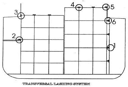
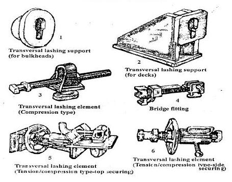
- If only twistlocks are used, during rolling a horizontal force is exerted on the twistlocks especially the lowest one which bears the maximum force of the entire stack load.
- This could cause the twistlocks to give way or the deck to be ripped off.
- The transversal lashing system solves a lot of these problems when used in certain types of vessels.
- The principle of this system is to transmit all horizontal forces arising from ship’s rolling at a reinforced part of the ship’s structure.
- A transverse lashing element is then wedged between the container block and the ship’s structure at the level of the corner fittings of the upper tiers on port and stbd side.
- These transverse elements absorb the horizontal forces generated by the container.
- Transversal elements can be pressure or tension pressure type.
- If tension-pressure type is used on each side, the horizontal force is split into two and each element bears half the force, one pulling the container block and the other pushing it.
- This keeps the force on the corner fittings within limits.
- However, where the horizontal forces are not large, pressure elements can be used wherein the one on which side the roll is, bears the full force, while the other remains idle.
- The arrangement of transverse elements may vary according to the number of tiers and slacks and the availability of strong support in the ship’s structure such as decks, hatch coamings, frames or longitudinal.
- However a suitable distribution of forces must be achieved.
- The foundations for the transversal elements should be preferable be of the flush type so that loading/ unloading operations are not hindered and the ability to load other types of cargoes is not compromised.
- The distance between the container block and the hull structure must be reasonably small (within 1.5m), if not the size of the transverse elements will make them difficult to handle.
- Large elements element may sometimes be permanently suspended instead of being removable which allows for better handling.
Container Code (CSC):
The technical requirements placed on containers are enshrined in the “International Convention for Safe Containers” or CSC. Prepared under the auspices of IMO, CSC makes it obligatory for the owners of containers to follow ISO standards which govern safety – specifications & testing.
The aim of the Convention is to achieve the highest possible level of safety of human life in the handling, stacking and transporting of containers. The Convention applies to all containers used for international transport, except containers developed especially for air travel.
Annex II of the CSC gives examples of structural safety requirements and tests:-
Every contracting state must ensure that effective procedures are put in place to enforce the regulations in Annex I of the Convention. This Annex sets out regulations for the testing, inspection, approval and maintenance of containers. However, the text of the Convention does allow duly authorized organizations to be entrusted with all these tasks, other than maintenance. In many countries, the national classification societies are entrusted with these tasks, e.g. Germanischer Lloyd in Germany.
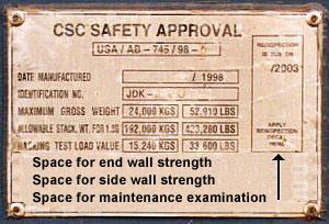
A Safety Approval Plate must be permanently affixed to every container at a readily visible place, where it cannot be easily damaged.
Annex I to the International Convention for Safe Containers” (CSC) sets out regulations for the testing, inspection, approval and maintenance of containers. Regulation 1 deals with the Safety Approval Plate. Point 1 makes the following statements:
CSC Plate
The Plate shall contain the following information in at least the English or French language:
- “CSC SAFETY APPROVAL”.
- Country of approval and approval reference.
- Date (month and year) of manufacture.
- Manufacturer’s identification number of the container.
- Maximum operating gross weight (kilograms and lbs).
- Allowable stacking weight for 1.8 g (kilograms and lbs).
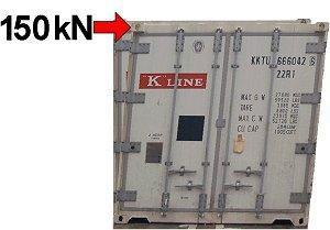
- Transverse racking test load value.
The Safety Approval Plate … shall take the form of a permanent, non-corrosive, fire-proof rectangular plate measuring not less than 200 mm by 100 mm. The words “CSC Safety Approval” of a minimum letter height of 8 mm and all other words and numbers of a minimum height of 5 mm shall be stamped into, embossed on or indicated on its surface in any other permanent and legible way.
- Country of Approval and Approval Reference is in this case the USA, the certifier is AB, standing for the American Bureau of Shipping, the reference is 745.
- Date (month and year) of manufacture is year: 1998 and month: September (stated according to ISO standard as 98-9)
- Manufacturer’s identification number of the container is JDK …and so on.
- Maximum operating gross weight (kilograms and lbs) is stated
as 24,000 KGS and 52,910 LBS (i.e. pounds). According to the original DIN/ISO standards, the maximum total mass for a 20′ container is 20,320 kg. In the example it is therefore higher, which is not uncommon these days. Containers with a markedly higher total weight are available. - Allowable stacking weight for 1.8 g (kilograms and lbs) According to ISO standards, fully loaded containers must be stackable 6 high. The container given by way of example may be stacked 8 high (192,000 kg ÷ 24,000 kg = 8).
- Transverse racking test load value. In this instance, this value is 15,240 KGS or 33,600 LBS.
A blank space should be reserved on the Plate for insertion of end and/or side-wall strength values (factors). A blank space should also be reserved on the Plate for first and subsequent maintenance examination dates (month and year) when used.
The CSC Safety Approval Plates illustrated above do not carry these details. With good reason, since the regulations subsequently state:
End Wall Strength to be indicated on plate only if end walls are designed to withstand a load of less or greater than 0.4 times the maximum permissible payload, i.e. 0.4 P.
Side Wall Strength to be indicated on plate only if the side walls are designed to withstand a load of less or greater than 0.6 times the maximum permissible payload, i.e. 0.6 P.

Positioning of data on the Safety Approval Plate
“A blank space should also be reserved on the CSC Plate for first and subsequent maintenance examination dates (month and year) when used.“
In the example illustrated, this blank space has been left not at the bottom but on the right of the other required data (see arrow). This is common practice.
In the “International Convention for Safe Containers”, Regulation 2 of Annex I deals with maintenance, and reads as follows:
The owner of the container shall be responsible for maintaining it in safe condition.
The owner of an approved container shall examine the container or have it examined in accordance with the procedure either prescribed or approved by the Contracting Party concerned, at intervals appropriate to operation conditions. The date (month and year) before which a new container shall undergo its first examination shall be marked on the Safety Approval Plate.
The date (month and year) before which the container shall be re-examined shall be clearly marked on the container on or as close as practicable to the Safety Approval Plate and in a manner acceptable to that Contracting Party which prescribed or approved the particular maintenance procedure involved.
The interval from the date of manufacture to the date of the first examination shall not exceed five years. Subsequent examination of new containers and re-examination of existing containers shall be at intervals of not more than 24 months. All examinations shall determine whether the container has any defects which could place any person in danger.
For some years now, owners have in most cases been responsible for examining their own containers. Regulators have provided for this by establishing an “Approved Continuous Examination Program“, in which owners participate. The ACEP is a recognized repair and maintenance system providing for regular examinations and servicing. To participate actively in this program, it is necessary to register with the competent authorities. Registration is indicated on the container. The owner has then to take responsibility for the necessary inspections and the date for re-examination need no longer be indicated on the CSC plate.
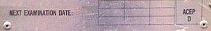
A valid ACEP renders it unnecessary to indicate a next examination date.
-
 Cargo Solved MMD Past Papers Phase 1 Chief MatePrice range: ₹ 244.00 through ₹ 576.00
 -
 2nd Mate (F.G.) & NCV (NWKO) – Volume 3 (Cargo)₹ 219.00
 -
 Cargo Consolidated Notes for Phase 1 Chief Mate₹ 361.00
Factors to be considered for Preparing a Container Loading Plan:
As a deck officer, the main responsibilities are safe navigation of ship and safe cargo handling and stowage. As the rank or responsibility of the deck officer rises, the cargo handling and stowage knowledge is must for a competent deck officer for the safety of the ship’s property and personnel.
In a container ship, a stowage plan is prepared as per the container to be discharge and loaded on a particular port along with the tanks condition i.e. mass carried by the ship other than cargo. This is done to maintain the stability of the ship at all times. Chief Officer of the ship is responsible for safe and secure stowage of the cargo on ships.
Objectives when cargo is stowed in the ship –
- To protect the ship.
- To protect the cargo.
- To obtain the maximum use of the available capacity of the ship.
- To provide for rapid and systematic discharging and loading.
- To provide for the safety of crew and shore men at all times.
Points to remember when loading cargo container on ships:
Over stowage should be avoided and cargo planning to be done as per the latest cargo, i.e. cargo for a later port should not be placed over that of an earlier port.
Loading conditions must be calculated for intact stability, shearing force, bending moment, torsion moment, trim and draft etc. Torsion moment, bending moment and shear force values must not exceed 100% at any time.
The IMO visibility line should be taken care of when planning the stowage of containers on deck.
The stowage of IMDG containers to be done as per ships Document of compliance with the special requirements for ships carrying dangerous goods
The GM value is affected (increases/decreases) by means of stowing light containers on top of heavy containers respectively and vice-versa.
GM is the also known as Metacentric height which is the distance between the centre of gravity of the ship and its metacentre. The GM is responsible for deciding the stability factor of the ship.
In a low GM situation, it is preferable for light containers to be stowed on top.
However, usually the GM values for ship are high and stowing light containers on top of heavy ones will only increase GM leading to a “stiff” ship with short rolling periods, which increases the stresses on the lashing.
In this situation, it is preferable for the heavy containers to be loaded on top but with due regard to lashing stresses and staking weight.
Out of Gauge or OOG Containers:-
OOG containers are the ones for which standard lashing equipment and procedures cannot be applied.
OOG should not be stored in outboard rows in order to prevent the OOG cargo from falling overboard if lashings break.
Stowage of OOG on deck in the foremost bay is never permitted. If possible stowage of OOG on deck of the second most forward bay also to be avoided;the main thing is to check the lashing of the OOG cargo as the stevedores lash them after loading. The OOG cargo should be secured properly and it should be ensured that the OOG cargo won’t shift or break loose.
Design & Construction Requirements:
- The general design and construction requirements of this sub-section are deemed to be met if the bulk container complies with the requirements of ISO 1496-4:1991 “Series 1 Freight containers – Specification and testing – Part 4: Non pressurized containers for dry bulk” and the container is siftproof.
- Containers designed and tested in accordance with ISO 1496-1:1990 “Series 1 Freight containers – Specification and testing – Part 1: General cargo containers for general purposes” shall be equipped with operational equipment which, including its connection to the container, is designed to strengthen the end walls and to improve the longitudinal restraint as necessary to comply with the test requirements of ISO 1496- 4:1991 as relevant.
- Bulk containers shall be siftproof. Where a liner is used to make the container siftproof it shall be made of a suitable material. The strength of material used for, and the construction of, the liner shall be appropriate to the capacity of the container and its intended use. Joins and closures of the liner shall withstand pressures and impacts liable to occur under normal conditions of handling and carriage. For ventilated bulk containers any liner shall not impair the operation of ventilating devices.
- The operational equipment of bulk containers designed to be emptied by tilting shall be capable of withstanding the total filling mass in the tilted orientation.
- Any movable roof or side or end wall or roof section shall be fitted with locking devices with securing devices designed to show the locked state to an observer at ground level.
Non-standardized Stowage & Securing:-
- Chapter 5 of “Code of Safe Practice for Cargo Stowage and Securing” and the annexes provide advice of a general nature for the stowage and securing of cargoes not covered by chapters 3 and 4 of this Code and particularly specific advice for the stowage and securing of cargoes which have proved to be difficult to stow and secure on board ships.
- The list of cargoes given in 5.3 should not be regarded as exhaustive, as there may be other cargoes which could create hazards if not properly stowed and secured.
Equivalent Stowage & Securing:-
The guidance given in the annexes provides for certain safeguards against the problems inherent in the cargoes covered. Alternative methods of stowage and securing may afford the same degree of safety. It is imperative that any alternative method chosen should provide a level of securing safety at least equivalent to that described in the resolutions, circulars and guidelines listed in the foreword to this Code.
Cargoes which have proved to be a potential source of danger.
Such Cargoes include:
- Containers when carried on deck of ships which are not specially designed and fitted for the purpose of carrying containers (annex 1);
- Portable tanks (tank-containers) (annex 2);
- Portable receptacles (annex 3);
- Special wheel-based (rolling) cargoes (annex 4);
- Heavy cargo items such as locomotives, transformers, etc. (annex 5);
- Coiled sheet steel (annex 6);
- Heavy metal products (annex 7);
- Anchor chains (annex 8);
- Metal scrap in bulk (annex 9);
- Flexible intermediate bulk containers (FIBCs) (annex 10);
- Logs in under-deck stow (annex 11); and
- Unit loads (annex 12).
Securing Arrangements of Rolled Steel & Steel Coils:-
Normally, coils of sheet steel have a gross mass in excess of 10 tonnes each.
Coils:-
- Coils should be given bottom stow and, whenever possible, be stowed in regular tiers from side to side of the ship.
- Coils should be stowed on dunnage laid athwart ships. Coils should be stowed with their axes in the fore-and-aft direction. Each coil should be stowed against its neighbor. Wedges should be used as stoppers when necessary during loading and discharging to prevent shifting.
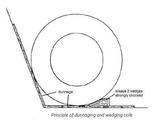
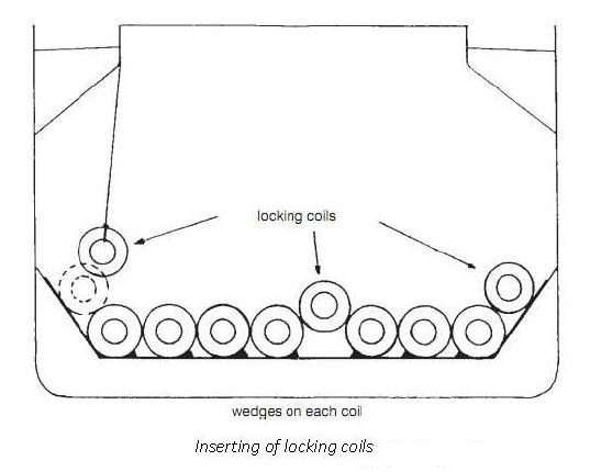
- The final coil in each row should normally rest on the two adjacent coils. The mass of this coil will lock the other coils in the row.
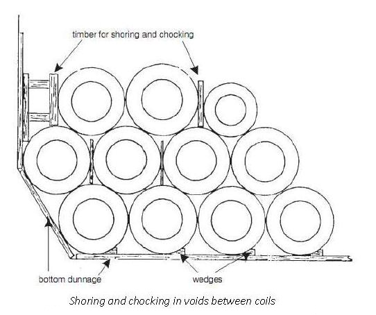
- If it is necessary to load a second tier over the first, then the coils should be stowed in between the coils of the first tier (figure 9).
- Any void space between coils in the topmost tier should be adequately secured (figure 10).
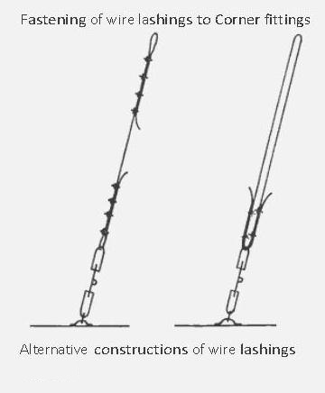
Lashings:-
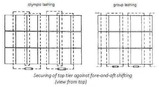
- The objective is to form one large, immovable block of coils in the hold by lashing them together. In general, strip coils in three end rows in the top tier should be lashed. To prevent fore-and-aft shifting in the top tier of bare-wound coils, group-lashing should not be applied due to their fragile nature; the end row of a top tier should be secured by dunnage and wires, which are to be tightened from side to side, and by additional wires to the bulkhead. When coils are fully loaded over the entire bottom space and are well shored, no lashings are required except for locking coils.
- The lashings can be of a conventional type using wire, steel band or any equivalent means.
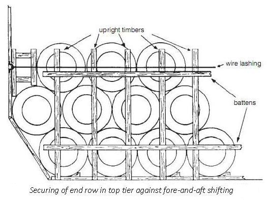
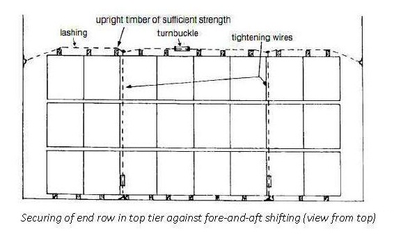
- Conventional lashings should consist of wires having sufficient tensile strength. The first tier should be chocked. It should be possible to retighten the lashings during the voyage (figures 12 and 13).
- Wire lashings should be protected against damage from sharp edges.
- If there are few coils, or a single coil only, they should be adequately secured to the ship, by placing them in cradles, by wedging, or by shoring and then lashing to prevent transverse and longitudinal movement.
- Coils carried in containers, railway wagons and road vehicles should be stowed in cradles or specially made beds and should be prevented from moving by adequate securing.
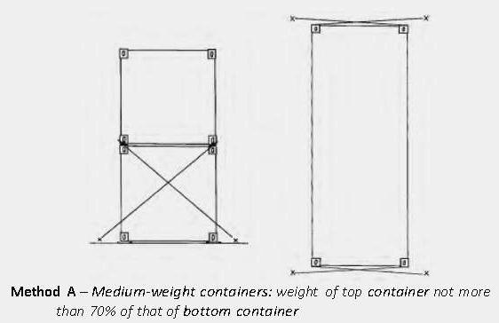
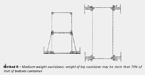
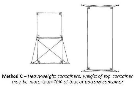
Safe stowage and securing of containers on deck of ships which are not specially designed and fitted for the purpose of carrying containers:-
Stowage
- Containers carried on deck or on hatches of such ships should preferably be stowed in the fore-and-aft direction.
- Containers should not extend over the ship’s sides. Adequate supports should be provided when containers overhang hatches or deck structures.
- Containers should be stowed and secured so as to permit safe access for personnel in the necessary operation of the ship.
- Containers should at no time overstress the deck or hatches on which they are stowed.
- Bottom-tier containers, when not resting on stacking devices, should be stowed on timber of sufficient thickness, arranged in such a way as to transfer the stack load evenly on to the structure of the stowage area.
- When stacking containers, use should be made of locking devices, cones, or similar stacking aids, as appropriate, between them.
- When stowing containers on deck or hatches, the position and strength of the securing points should be taken into consideration.
Securing
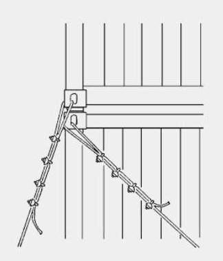
- All containers should be effectively secured in such a way as to protect them from sliding and tipping. Hatch covers carrying containers should be adequately secured to the ship.
- Containers should be secured using one of the three methods recommended in figure 1 or methods equivalent thereto.
- Lashings should preferably consist of wire ropes or chains or material with equivalent strength and elongation characteristics.
- Timber shoring should not exceed 2 m in length.
- Wire clips should be adequately greased, and tightened so that the dead end of the wire is visibly compressed (figure 2).
- Lashings should be kept, when possible, under equal tension.