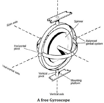
Explanation of a Free Gyroscope:
Gyroscope having three degrees of freedom is called “FREE GYROSCOPE”
Properties of Free Gyroscope:-
- Gyroscopic inertia or rigidity in space
- Precession
- Gyroscopic Inertia:- A freely spinning gyroscope will maintain its axis of spin in the same direction with respect to space irrespective of how its supporting base is turned. It resists any attempt to change its direction of spin. Thus a free gyroscope has high directional stability. This property is called GYROSCOPIC INERTIA or RIGIDITY IN SPACE.
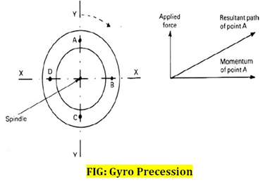
- Gyro Precession:- Precession is the angular displacement of the spin axis of the gyroscope when a torque is applied to gyroscope. Hence, when a torque is applied to the spin axis the resulting movement will be in the direction at right angle to the applied torque. Earth is also a free gyroscope pointing north axis toward Polaris. (rigidity in space). We all are also aware that earth also possesses force of gravity.
First property of free gyro scope is useful. However, due to the placing of this gyroscope on the surface of the earth it will be moved along the direction of rotation of the earth. As such the gyroscope will have an apparent motion. For example, at night if the gyroscope is made to point in the direction of a star, then the gyroscope will follow the star as the earth rotates and the star apparently moves in the sky.
Tilt and Drift in a Gyro compass
- Tilt is elevation or depression of the spin axis above or below the horizon.
- Drift is the movement of the spin axis in the direction of azimuth.
- Rate of tilting in degrees per hour = 15O sine Azimuth * cosine Latitude
- Rate of Drift in degrees per hour = 15O sine Latitude
Tilt:-
- If a free gyroscope is situated on the equator and lies with its axis East West and horizontal, it can be assumed of as pointing to a star with zero declination and is about to rise.
- The East End of the gyroscope axis will follow the movement of this star and will tilt upwards as the star rises.
- After nearly six hours the axis will be vertical and after nearly twelve hours the gyroscope will have turned completely over with the axis again horizontal but now the original East end of the axis would be pointing to the star setting due West.
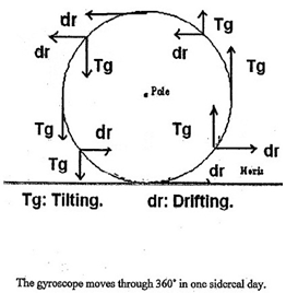
- After one sidereal day, the gyroscope would have tilted through 360O and the star would again be rising.
- This rate of tilting of 360O in a day is a rate of 15O per hour.
- If the gyroscope had been situated on the equator with its axis lying in the North – South direction, then the North end would be pointing towards the Pole star and would then have no apparent movement relative to the Earth.
- The rate of tilting thus varies from zero when the axis is lying North – South to a maximum when it is lying East – West. That is the rate of tilting varies as the Sine of the Azimuth.
- A free gyroscope situated at a pole with its axis horizontal would have an apparent turntable motion due to the Earth’s rotation.
- That is it would follow a fixed star around the horizon but it would not rise or set.
- The rate of tilting thus varies from a maximum when the latitude is 0O to zero when the latitude is 90O. That is the rate of tilting varies as the Cosine of the Latitude.
- Rate of tilting in degrees per hour = 15O sine Azimuth * cosine Latitude.
- The direction of tilting is such that the end of the gyroscope axis, which lies to the East of the meridian, tilts upwards and the end of the axis, which lies to the West of the meridian tilts downward.
Drift:-
- Drift is the apparent movement of a gyroscope in azimuth.
- A free gyroscope situated at the North Pole with its axis horizontal will have an apparent movement, which is entirely in the horizontal plane.
- Its axis will appear to move in a clockwise direction when viewed from above. This would be due to the real counter clockwise rotation of the earth beneath, this circular motion causes the gyroscope to drift through 360O in one sidereal day, that is at a rate of 15O per hour.
- A free gyroscope situated at the equator with its axis horizontal will not drift at all, irrespective of whether its axis is set in the North – South or East – West line.
- The rate of drift for a gyroscope with its axis horizontal thus varies from a maximum at the poles to zero at the equator.
- That is the rate of drift varies as the sine of the latitude. For a free gyroscope with its axis horizontal: Rate of Drift in degrees per hour = 15O sin Latitude. The direction of drift depends upon hemisphere so that the North end of a horizontal gyroscopic axis drifts to the eastwards in the Northern hemisphere but to the Westwards in the southern hemisphere.
Course, Latitude and Speed Error in a Gyro Compass:
- The gyro compass settles in the N/S direction by sensing Earth’s spinning motion. Same gyro compass when placed on a ship also senses the ship’s motion. And therefore, the axis of gyro compass settles in a direction which is perpendicular to the resultant of the Earth’s surface speed and the ship’s velocity.
- The direction, in which the compass settles, is therefore, different to the direction of the True North and depends on ship’s course, speed and latitude of the observer.
- This error also increases as the observer’s latitude increases. The error is westward on all Northerly courses and vice-versa. In exactly E-W courses, the error is nil. In exactly N-S courses, the error is maximum.
- To compensate for steaming error, a speed rider is provided, which in association with the latitude rider, shifts the lubber line equal to steaming error in the appropriate direction.


How is the Gyro Compass System made North Seeking?
North Seeking Gyro:-
- In order to damp unwanted oscillation, we need to achieve damping in tilt.
- This is done by means of offset slightly to the east of vertical, resulting in component of the same force producing the required torque.
- The magnitude and direction of this force is pre-calculated to achieve the required damping oscillation.
- The amplitude of each oscillation is reduced to 1/3rd of previous oscillation.
- The spin axis reaches equilibrium and settles in a position at which drifting is counteracted by control precession & the damping precession counteracts tilting.
- Finally, the gyro settles in the meridian & becomes north seeking.
Latitude course & speed error with respect to the Gyro Compass Explanation
Course, Speed and Latitude Error (Speed Error):-
- The gyro compass settles in the N/S direction by sensing Earth’s spinning motion.
Same gyro compass when placed on a ship also senses the ship’s motion and therefore, the axis of gyro compass settles in a direction which is perpendicular to the resultant of the Earth’s surface speed and the ship’s velocity. - The direction, in which the compass settles, is therefore, different to the direction of the True North and depends on ship’s course, speed and latitude of the observer.
- This error also increases as the observer’s latitude increases. The error is westward on all Northerly courses and vice-versa.
- In exactly E-W courses, the error is nil. In exactly N-S courses, the error is maximum.
- To compensate for speed error, a speed rider is provided, which in association with the latitude rider, shifts the lubber line equal to speed error in the appropriate direction.
- This error can be corrected automatically by a mechanism which moves the lubber line by an amount equal to the error, or it can be found from correction tables or from a portable correction calculator and then applied as necessary.
Three Degrees of Freedom:
As a mechanical device a gyroscope may be defined as a system containing a heavy metal wheel or rotor, universally mounted so that it has three degrees of freedom: spinning freedom, about an axis perpendicular through its center; tilting freedom, about a horizontal axis at right angles to the spin axis; and veering freedom, about a vertical axis perpendicular to both the other axes. The three degrees of freedom are obtained by mounting the rotor in two concentrically pivoted rings, called inner and outer rings. The whole assembly is known as the gimbal system of a free or space gyroscope. The gimbal system is mounted in a frame, so that in its normal operating position, all the axes are mutually at right angles to one another and intersect at the centre of gravity of the rotor.
Gyro Compass ‘Tangent Error’ Explanation
- On a non-pendulous gyrocompass where damping is accomplished by offsetting the point of application of the force of mercury ballistic, the angle between the local meridian and the settling position or spin axis.
- Where the offset of the point of application of mercury ballistic is to the east of the vertical axis of the gyrocompass, the settling position is to the east of the meridian in north latitudes and to the west of the meridian in south latitudes.
- The error is so named because it is approximately proportional to the tangent of the latitude in which the gyrocompass is operating.
- The tangent latitude error varies from zero at the equator to a maximum at high northern and southern latitudes.
Starting a Gyro Compass:
- A gyro needs time to settle on the meridian, the time taken will depend on the make, model & geographical location of the gyro.
- The settling time may be between one & several hours, manual provided by the manufacturer has to be consulted before switching on the gyro.
- If compass has been switched off, it will take longer time to bring compass into use.
- Following is the procedures for Sperry MK 37 digital.
- At power-up and prior entering the settling mode, system performs automatic procedure to determine if the equipment is operating within specified parameters.
- If gyro is stationary the system opts for cold start, if rotating a hot start if programmed.
- During a cold start, if no heading data is input to system when requested the gyro selects automatic. Once the power is switched on, two bleeps prompts for heading input, if the heading data is not entered within 5 minutes, the gyro switches to an auto level process. (In some older make, the slewing is done manually, a
special key is provided for the same which is inserted into a slot). - If heading data is fed the rotor is automatically slewed.
- The rotor is brought up to required speed within 14 minutes and the gyro will subsequently settle within an hour.
- If heading data is not fed, the gyro will settle within 5 hrs.
Some more points:-
- If entered heading is in error by more than 20 deg, gyro may take about 5 hours to settle.
- Once gyro is settled, synchronize the repeaters (radar & ECDIS also need synchronization.)
- If speed & latitude is fed manually, it should be done prior to starting the gyro.
- Once settled, compass error should be checked & compasses should be checked more frequently.