Hazards of Petroleum with Reference to:-
Toxicity:
ISGOTT 1.2 – Toxicity:- Toxicity is the degree to which a substance or mixture of substances can harm humans or animals.
Toxic substances can affect humans in four main ways: by being swallowed (ingestion); through skin contact; through the lungs (inhalation) and through the eyes.
Ingestion:
Petroleum has low oral toxicity, but when swallowed it causes acute discomfort and nausea. There is then a possibility that liquid petroleum may be drawn into the lungs during vomiting and this can have serious consequences, especially with higher volatility products, such as gasolines and kerosenes.
Skin Contact:
Many petroleum products, especially the more volatile ones, cause skin irritation and remove essential oils from the skin, leading to dermatitis. They are also irritating to the eyes. Certain heavier oils can cause serious skin disorders on repeated and prolonged contact.
Direct contact with petroleum should always be avoided by wearing the appropriate protective equipment, especially impermeable gloves and goggles.
Petroleum Gases:
Comparatively small quantities of petroleum gas, when inhaled, can cause symptoms of diminished responsibility and dizziness similar to drunkenness, with headache and irritation of the eyes. The inhalation of a sufficient quantity can be fatal.
These symptoms can occur at concentrations well below the Lower Flammable Limit.
However, petroleum gases vary in their physiological effects and human tolerance to these effects also varies widely. It should not be assumed that because conditions can be tolerated the gas concentration is within safe limits.
The smell of petroleum gas mixtures is very variable and in some cases the gases may dull the sense of smell. The impairment of smell is especially likely, and particularly serious, if the mixture contains hydrogen sulphide.
The absence of smell should never be taken to indicate the absence of gas.
Primary & Secondary means of Venting on Oil Tankers:
Primary means of Venting : Vessels utilising a common gas / vapour system as the “primary means of venting” which is isolated from a cargo tank by a valve, or other means, which is shut due to the normal operation of the vessel (such as in the case of a vessel carrying parcel cargo with non-compatible vapours) are not in compliance with the requirements of SOLAS Reg. II-2/4.5.3 unless they have a second independent means of venting which cannot be isolated from the cargo tank.
Secondary means of Venting: (Reg. II-2/4.5.3.2.2) Where the arrangements are combined with other cargo tanks, either stop valves or other acceptable means shall be provided to isolate each cargo tank. Where stop valves are fitted, they shall be provided with locking arrangements which shall be under the control of the responsible ship’s officer. There shall be a clear visual indication of the operational status of the valves or other acceptable means. Where tanks have been isolated, it shall be ensured that relevant isolating valves are opened before cargo loading or ballasting or discharging of those tanks is commenced. Any isolation must continue to permit the flow caused by thermal variations in a cargo tank in accordance with regulation 11.6.1.1.
Differentiate between PV valve & PV Breaker:
| PV VALVE | P/V BREAKER |
| Connected On Tank Top Of individual Cargo Tank | Connected To Main Inert Gas Line |
| 1 or 2 per tank | 1 on main IG line |
| Mechanical Type | Gravity Type ( Liquid) |
| PRESSURE :+1400 mmaq | PRESSURE :+2100 mmaq |
| VACCUM : -350mmaq | VACCUM : -700 mmaq |
| Primary Means Of Protection | Secondary Means Of Pretection |
| Requires Regular Maintenance | Less Maintenance |
| Fixed Set-Point | SET POINT CANBE INCREASED OR DECREASED |
| Automatic Self-Closing Checklifts | Automatic Self-Closing Checklifts NOT AVAILABLE |
| Check Lift AVAILABLE TO CHECK THE OPERATIONAL CONDITION | WATER LEVEL GAUGE AVAILABLE TO CHECK THE PRESSURE& VACCUM SETTING |
| System Failure May Occur | 100% Reliable |
| No extra precaution in cold climate | Antifreeze required in cold climate |
Precautions to be taken on an Oil Tanker during Loading, Discharging and Tank Cleaning against Static Electricity Hazard:
- The following are essential only when loading static accumulator oils (conductivity < 50 pS/m): Restrict initial loading rates, when splashing and surface turbulence occur, to flow rates less than 1 meter/second (volume flow rate conversions available).
- Adequate inlet coverage’s are: side or horizontal entrance- 0.6 meter; downward pointing inlet- twice the inlet diameter.
- ISGOTT %B7 Loading rate conversions appear both in ISGOTT and Texaco. %B7 Restrict initial unloading rates to shore installations also, as long as inlets in the shore tank are not covered with liquid. The inlet fill pipe should discharge near the bottom of the tank. NFPA 77 %B7 Keep water and other impurities out of the incoming cargo stream as much as possible.
- Extra care with loading and unloading rates when presence of impurities (e.g., water, sulfur, metals) is suspected is essential. ISGOTT, NFPA 77 %B7 Avoid pumping entrained gases with cargo.
- NFPA 77 %B7 Degassing (to <20% of LFL at tank bottom) or inerting a ship’s tank eliminates loading rate restrictions due to static electricity. Texaco %B7 Reduced pumping speeds are used for discharge of slops and other “mixed-phase flow” (some ballast) to shore tanks.
- Prevention of charge accumulation – recommended by ISGOTT /NFPA 77.
The following safety precautions have been developed to prevent the accumulation of static charge:
- Antistatic additives:- These additives raise the conductivity of a static accumulator; one specification calls for a minimum of 100 pS/m.
- ISGOTT Treatment is required for these fuels in Canada:- The Canadian General Standards Board specifies minimum conductivity of 50 pS/m for static accumulating fuels, especially aviation fuels .
- API 2003 recommends that these additives be introduced at the beginning of the “distribution train”, and notes that their positive effect may be reduced by repeated shipments or passage through clay filters. Safety precautions for the handling of static accumulating oils have historically been waived for those treated with antistatic additives.
- These precautions have, however, recently been extended to residual oils and oils treated with anti-static additive to raise conductivity above 50 pS/m (May 1991 amendment to ISGOTT).
- Space is too small to give full details. You can get ample literature / case histories of such accidents from published journals and published symposium. Basically, this problem can be a great extent mitigarted if:
- A firm earthing connection exists between tank top to bottom on all sides (four quandrantss), measurement of earthing measuremens once in 6 months to meet both Indian Electricity regulations, as well Indian Petrolem and over all for API construction code requirements, firm earthing at all jump-over points(especially piping joints in and out of tanks).
- Allowing enough settling time betwenn tank loading and allow time for tank discharge (i.e, withdrawal of naphtha), good lightning arrestor at the top of the tanks and the continuity of the same will help you to avoid major catastrophy in naphtha storage tanks – inspie of unpreventable static electric discharge.
- As a precaution, do not load the tank too fast or take fuel discharge during severe lightning time.
Dirty Ballast:
- This intermitted discharge is composed of the seawater taken into, and discharged from empty fuel tanks to maintain the stability of the vessel. The seawater is brought into these tanks for the purpose of improving the stability of a vessel during rough sea conditions.
- Prior to taking on the seawater as ballast, fuel in the tank to be ballasted is transferred to another fuel tank or holding tank to prevent contaminating the fuel with seawater.
- Some residual fuel remains in the tank and mixes with the seawater to form dirty ballast.
- Dirty ballast systems are configured differently from Compensated ballast and Clean ballast systems.
- Compensated ballast systems continuously replace fuel with seawater in a system of tanks as the fuel is consumed.
- Clean ballast systems have tanks that carry only ballast water and are never in contact with fuel.
- In a dirty ballast system, water is added to a fuel tank after most of the fuel is removed.
- Thirty Coast Guard vessels generate dirty ballast as a discharge incidental to normal vessel operations. These Coast Guard vessels do so because their size and design do not allow for a sufficient volume of clean ballast tanks.
- The larger of these vessels discharge the dirty ballast at distances beyond 12 n.m. from shore, while the smaller vessels discharge the dirty ballast between 3 and 12 n.m. from shore. Coast Guard vessels monitor the dirty ballast discharge with an oil content monitor. If the dirty ballast exceeds 15 parts per million (ppm) oil, it is treated in an oil-water separator prior to discharge.
Cloud Point:
In the petroleum industry, cloud point refers to the temperature below which wax in diesel or bio-wax in bio-diesels form a cloudy appearance. The presence of solidified waxes thickens the oil and clogs fuel filters and injectors in engines. The wax also accumulates on cold surfaces (e.g. pipeline or heat exchanger fouling) and forms an emulsion with water. Therefore, cloud point indicates the tendency of the oil to plug filters or small orifices at cold operating temperatures.
In crude or heavy oils, cloud point is synonymous with wax appearance temperature (WAT) and wax precipitation temperature (WPT).
The cloud point of a nonionic surfactant or glycol solution is the temperature where the mixture starts to phase separate and two phases appear, thus becoming cloudy. This behavior is characteristic of non-ionic surfactants containing polyoxyethylene chains, which exhibit reverse solubility versus temperature behavior in water and therefore “cloud out” at some point as the temperature is raised. Glycols demonstrating this behavior are known as “cloud-point glycols” and are used as shale inhibitors (see Talk). The cloud point is affected by salinity, being generally lower in more saline fluids.
Spiked Crude Oil:
- “Spiked crude oil” (also called “enriched” or “tailored” crude) is crude oil, which has had hydrocarbons, added in gas or liquid form.
- The spiked crude may contain rather large amounts of added hydrocarbons and therefore emit heavy gasses under certain conditions (during loading, crude oil washing, discharging).
Sour Crude:
- Sour crude oil is crude oil containing a high amount of the impurity sulfur. It is common to find crude oil containing some impurities. When the total sulfur level in the oil is more than 0.5% the oil is called “sour”.
- The impurities need to be removed before this lower-quality crude can be refined into petrol, thereby increasing the cost of processing. This results in a higher-priced gasoline than that made from sweet crude oil.
- Current environmental regulations in the United States strictly limit the sulfur content in refined fuels such as diesel and gasoline.
- The majority of the sulfur in crude oil occurs bonded to carbon atoms, with a small amount occurring as elemental sulfur in solution and as hydrogen sulfide gas. Sour oil can be toxic and corrosive, especially when the oil contains higher levels of hydrogen sulfide, which is a breathing hazard. At low concentrations the gas gives the oil the smell of rotting eggs. For safety reasons, sour crude oil needs to be stabilized by having hydrogen sulfide gas (H2S) removed from it before being transported by oil tankers.
Pour Point:
- The pour point is the lowest temperature at which a marine fuel oil can be handled without excessive amounts of wax crystals forming out of solution.
- At a lower temperature the fuel will gel, thereby preventing flow.
Precautions you will observe while loading Crude Oil having very high Concentration of Hydrogen Sulphide:
Bunker fuels containing high H2S concentrations may be supplied without advice being passed to the tanker beforehand. Tanker’s personnel should always be alert to the possible presence of H2S in bunker fuel and be prepared to take suitable precautions if it is present.
- Before loading bunkers, the tanker should communicate with the supplier to ascertain whether the fuel to be loaded is likely to have any H2S content.
- The design of bunker tank vents and their location makes managing the exposure to personnel more difficult, as closed loading and venting cannot usually be implemented.
- If bunkering with fuel containing H2S above the TLV-TWA cannot be avoided, procedures should be in place to monitor and control the access of personnel to exposure areas.
- Ventilation to lower the concentration of vapour in the ullage space and in specific areas where vapours may accumulate should be carried out as soon as practicable.
- Even after the tank has been ventilated to reduce the concentration to an acceptable level, subsequent transfer, heating and agitation of the fuel within a tank may cause the concentration to reappear.
- Periodic monitoring of the concentration of H2S should be continued until the bunker tank is refilled with a fuel oil not containing H2S.
Sketch Wet Type “Deck Seal” & the required water level is maintained:
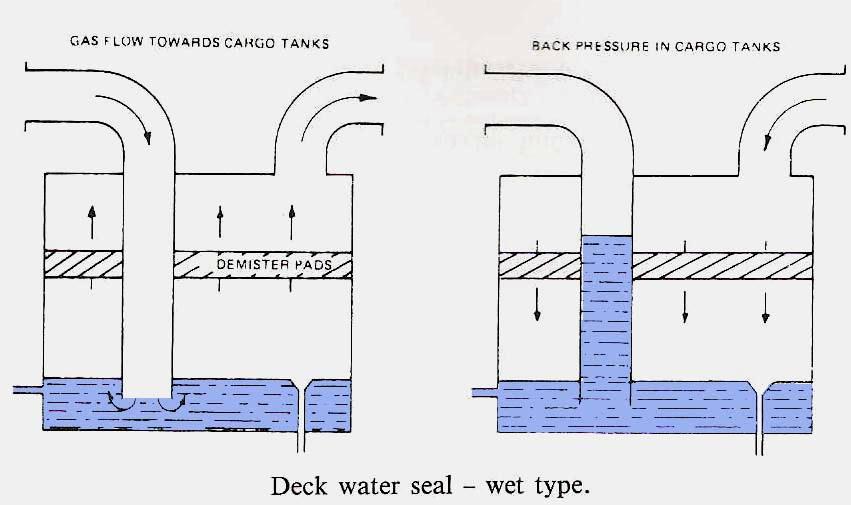
- The seal is kept full using a continuously running seal water pump which may be backed up with a crossover from a secondary system as required.
- Should the pressure on the downstream side exceed the upstream side the water is pushed up the inlet pipe.
- The height of this pipe ensures that the head pressure generated is greater than either the pressure release valve or any water seals.
Sketch High Velocity (HV) vent valve fitted in Cargo Oil Tanks:
- Tank vapours can be released and sent clear of the decks during loading through large, high velocity vent.
- The type shown above has a moving orifice, held down by a counter weight to seal around the bottom of a fixed cone.
- Pressure build up in the tank, as filling proceeds, causes the moving orifice to lift.
- The small gap between orifice lip and fixed cone gives high velocity to the emitted vapour.
- It is directed upwards with an estimated velocity of 30 meters per second.
- Air drawn in by the ejector effect dilutes the plume.
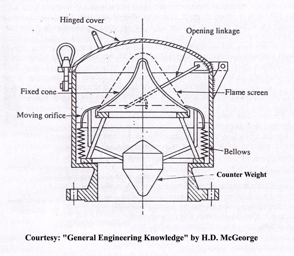
- The conical flame screen fixed to the moving orifice to give protection against flame travel will, like the moving parts, require periodic cleaning to remove gummy deposit.
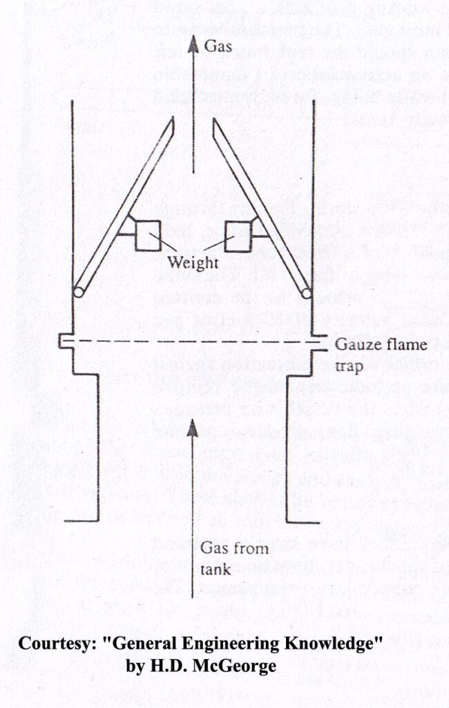
- The cover is closed (as shown) when the vessel is on passage. A simpler design of a high velocity vent, having two weighted flaps which are pushed open by the pressure build up to achieve a similar nozzle effect.
Precautions to be taken on an Oil Tanker during loading/ discharging against Static Electric Hazard:
- Restrict initial loading rates, when splashing and surface turbulence occur, to flow rates less than 1 meter/second (volume flow rate conversions available). Adequate inlet coverage’s are: side or horizontal entrance- 0.6 meter; downward pointing inlet- twice the inlet diameter. ISGOTT
- Loading rate conversions appear both in ISGOTT and Texaco.
- Restrict initial unloading rates to shore installations also, as long as inlets in the shore tank are not covered with liquid. The inlet fill pipe should discharge near the bottom of the tank. NFPA 77
- Keep water and other impurities out of the incoming cargo stream as much as possible. Extra care with loading and unloading rates when presence of impurities (e.g., water, sulfur, metals) is suspected is essential. ISGOTT, NFPA 77
- Avoid pumping entrained gases with cargo. NFPA 77
- Degassing (to <20% of LFL at tank bottom) or inerting a ship’s tank eliminates loading raterestrictions due to static electricity.
- Reduced pumping speeds are used for discharge of slops and other “mixed-phase flow” (some ballast) to shore tanks.
International Safety Guide for Tankers and Terminals – ISGOTT
- This Guide makes recommendations for tanker and terminal personnel on the safe carriage and handling of crude oil and petroleum products on tankers and at terminals.
- It was first published in 1978 by combining the contents of the ‘Tanker Safety Guide (Petroleum)’ published by the International Chamber of Shipping (ICS) and the ‘International Oil Tanker and Terminal Safety Guide’ published on behalf of the Oil Companies International Marine Forum (OCIMF).
- This latest edition takes account of recent changes in recommended operating procedures, particularly those prompted by the introduction of the International Safety Management (ISM) Code, which became mandatory for tankers on 1st July 1998.
- One of the purposes of the Guide is therefore to provide information that will assist companies in the development of a Safety Management System to meet the requirements of the ISM Code.
- This guide does not provide a definitive description of how tanker and terminal operations are conducted. It does provide guidance and examples of how certain aspects of tanker and terminal operations may be managed.
- Effective management of risk demands processes and controls that can quickly adapt to change. Therefore the guidance given is, in many cases, intentionally non prescriptive and alternative procedures may be adopted by some operators in the management of their operations.
- These alternative procedures may exceed the recommendations contained in this guide.
- Where an operator has adopted alternative procedures, they should follow a risk based management process that must incorporate systems for identifying and assessing the risks and for demonstrating how they are managed. For shipboard operations, this course of action must satisfy the requirements of the ISM Code.
- It should be borne in mind that, in all cases, the advice in the guide is subject to any local or national terminal regulations that may be applicable, and those concerned should ensure that they are aware of any such requirements.
- It is recommended that a copy of the guide be kept — and used — on board every tanker and in every terminal to provide advice on operational procedures and the shared responsibility for port operations.
For contents please refer to ISGOTT (Latest Edition)
Slop Tanks:
Marpol Annex I- Regulations for the Prevention of Pollution by Oil
Chapter 4 – Requirements for the cargo area of oil tankers. Part A – Construction.
Regulation 29 – Slop tanks
- Subject to the provisions of paragraph 4 of regulation 3 of this Annex, oil tankers of 150 gross tonnage and above shall be provided with slop tank arrangements in accordance with the requirements of paragraphs 2.1 to 2.3 of this regulation. In oil tankers delivered on or before 31 December 1979, as defined in regulation 1.28.1, any cargo tank may be as a slop tank.
2.1 Adequate means shall be provided for cleaning the cargo tanks and transferring the dirty ballast residue and tank washings from the cargo tanks into a slop tank approved by the Administration.
2.2 In this system arrangements shall be provided to transfer the oily waste into a slop tank or combination of slop tanks in such a way that any effluent discharged into the sea will be such as to comply with the provisions of regulation 34 of this Annex.
2.3 The arrangements of the slop tank or combination of slop tanks shall have a capacity necessary to retain the slop generated by tank washings, oil residues and dirty ballast residues. The total capacity of the slop tank or tanks shall not be less than 3 per cent of the oil-carrying capacity of the ship, except that the Administration may accept:
1} 2% for such oil tankers where the tank washing arrangements are such that once the slop tank or tanks are charged with washing water, this water is sufficient for tank washing and, where applicable, for providing the driving fluid for eductors, without the introduction of additional water into the system;
2} 2% where segregated ballast tanks or dedicated clean ballast tanks are provided in accordance with regulation 18 of this Annex, or where a cargo tank cleaning system using crude oil washing is fitted in accordance with regulation 33 of this Annex. This capacity may be further reduced to 1.5% for such oil tankers where the tank washing arrangements are such that once the slop tank or tanks are charged with washing water, this water is sufficient for tank washing and, where applicable, for providing the driving fluid for eductors, without the introduction of additional water into the system; and
3} 1% for combination carriers where oil cargo is only carried in tanks with smooth walls. This capacity may be further reduced to 0.8% where the tank washing arrangements are such that once the slop tank or tanks are charged with washing water, this water is sufficient for tank washing and, where applicable, for providing the driving fluid for eductors, without the introduction of additional water into the system.
Tank Cleaning, Purging and Gas free Operation for tankers:
Responsibility: –
- The Chief Officer is in charge of and shall supervise as the person in charge of the Tank Cleaning, Hydrocarbon Gas (HC) Purging, Gas Freeing & Re-Inerting operations.
- He shall ensure that all activities carried out during such operations are in compliance with the latest edition ICS/OCIMF International Safety Guide for Oil Tankers and Terminals (ISGOTT).
Gas-Freeing for Cargo Tank entry:-
- Cargo Tank entry shall not be permitted unless the Oxygen Content is 21% and the hydrocarbon vapor content is less than 1% of the Lower Flammable Level (LFL).
- Follow company’s “Procedure for Entry into Enclosed Spaces” with related permits.
- If the previous cargo contains Hydrogen Sulfide (H2S) or other toxic contaminants which could evolve toxic gases (eg benzene, toluene, Mercaptans, etc), the tank should be checked for such gases. Refer to “Guidelines for Toxic Gases Hazards”.
- Carrying out “Hot Work” inside Tanks within the ‘Dangerous Area’ need special caution as per “Procedures for Hot Work” and carry out preparation accordingly.
Gas-Freeing or Purging for the Reception of Cargo:-
- If the intention of Gas-Freeing or Purging operations is to prevent the next cargo to be loaded from contamination due to the previous cargo oil hydrocarbon gas, use the gas content indicated by the Charterer as standard, but go on with the operations mentioned in (2) of Article 1 until the LFL decreases down to 40% or under.
Safety Precautions:-
- For the operations to be followed, (Tank cleaning, HC Gas Purging, Gas Freeing and Re-Inerting), the Chief Officer shall carry out the following precautions. Detailed guidance on preparations and safety precautions are also described within relevant sections of ISGOTT.
- Have persons engaged in the operations observe the necessary precautions as described in this section and the “Precautions during Gas-freeing Operations”. Complete the necessary sections of “Tank Cleaning, Purging and Gas Freeing Checklist” to confirm safety strictly at the appropriate time.
- Tank Preparation And Atmosphere Control During Operations.
Non Flammable Atmosphere:-
- On Tankers using the inert gas systems, the Chief Officer shall carry out the operations mentioned in Article 1 and should maintain the cargo tanks in a “Non Flammable” condition at all times.
- Refer to the “Flammability composition diagram- Hydrocarbon Gas/Inert/Air Gas Mixtures” from the ISGOTT. i.e. at no time should the atmosphere in the tank be allowed to enter the flammable range, as mentioned therein.
- Pyrophoric hazards on chemical reaction with Hydrogen Sulfide Gas Pyrophoric Iron Sulphide, forms when Hydrogen Sulfide Gas (normally present in most crude) reacts with rusted surfaces in the absence of oxygen (Inert conditions) inside cargo tanks.
- These substances, can heat to incandescence on contact with air. This risk is minimized, by following the correct purging procedure.
- Such procedures serve as a general guidance for the preparation procedures required and may differ as per ship type.
Atmosphere Control during Tank Cleaning Operations:-
- Tank atmospheres can be any of the following, However, ships fitted with an inert gas system, shall carry out the operations under the Inerted Condition, unless otherwise as instructed: It should be met with atmosphere containing less than 8% oxygen, and tank pressure of minimum 200 mmAq. Refer details to “ISGOTT”
Inerted Tanks:-
- An atmosphere made incapable of burning by the introduction of inert gas and the resultant reduction of the overall oxygen content. For the purposes of this procedure, the oxygen content of the tank atmosphere should not exceed 8% by volume.
- This is a condition where the tank atmosphere is known to be at it’s the lowest risk of explosion by virtue of its atmosphere being maintained at all times Non-Flammable through the introduction of inert gas and the resultant reduction of the overall oxygen content in any part of any cargo tank to a level not exceeding 8% by Volume, while being under positive pressure at all times.
Purging with Inert Gas (IG) :-
- For reduction in hydrocarbon (HC) content in tank atmosphere for Cargo Vapor contamination reasons:
- After tank cleaning operations the cargo tanks may be purged with inert gas to reduce the concentration of the hydrocarbon gas inside the tank atmosphere.
- Follow the procedures as laid out in the operation and equipment manual.
- Purge pipes, with proper flame screens shall be fitted, where provided.
- Carry out the operations of replacing the tank atmosphere by introducing IG of which oxygen content is 5% by Volume or less into the tanks.
- Go on with purging by IG until the hydrocarbon content reduces to the required / desired level.
Segregated Ballast:
Annex I- Regulations for the Prevention of Pollution by Oil
Chapter 4 – Requirements for the cargo area of oil tankers
Part A – Construction
Regulation 18 – Segregated ballast tanks
Oil tankers of 20,000 tonnes deadweight and above delivered after 1 June 1982
- Every crude oil tanker of 20,000 tonnes deadweight and above and every product carrier of 30,000 tonnes deadweight and above delivered after 1 June 1982, as defined in regulation 1.28.4, shall be provided with segregated ballast tanks and shall comply with paragraphs 2, 3 and 4, or 5 as appropriate, of this regulation.
- The capacity of the segregated ballast tanks shall be so determined that the ship may operate safely on ballast voyages without recourse to the use of cargo tanks for water ballast except as provided for in paragraph 3 or 4 of this regulation. In all cases, however, the capacity of segregated ballast tanks shall be at least such that, in any ballast condition at any part of the voyage, including the conditions consisting of lightweight plus segregated ballast only, the ship’s draughts and trim can meet the following requirements:
- the moulded draught amidships (dm) in metres (without taking into account any ship’s deformation) shall not be less than:
- The capacity of the segregated ballast tanks shall be so determined that the ship may operate safely on ballast voyages without recourse to the use of cargo tanks for water ballast except as provided for in paragraph 3 or 4 of this regulation. In all cases, however, the capacity of segregated ballast tanks shall be at least such that, in any ballast condition at any part of the voyage, including the conditions consisting of lightweight plus segregated ballast only, the ship’s draughts and trim can meet the following requirements:
dm = 2.0 + 0.02L
- the draughts at the forward and after perpendiculars shall correspond to those determined by the draught amidships (dm) as specified in paragraph 2.1 of this regulation, in association with the trim by the stern of not greater than 0.015L; and
- in any case the draught at the after perpendicular shall not be less than that which is necessary to obtain full immersion of the propeller(s).
- In no case shall ballast water be carried in cargo tanks, except:
- the opinion of the master, it is necessary to carry additional ballast water in cargo tanks for the safety of the ship; and
- in exceptional cases where the particular character of the operation of an oil tanker renders it necessary to carry ballast water in excess of the quantity required under paragraph 2 of this regulation, provided that such operation of the oil tanker falls under the category of exceptional cases as established by the Organization.
Reid Vapour Pressure:
Reid Vapour Pressure (RVP) is measured by ASTM D-323 testing method. The sample is placed in a chamber at a constant temperature of 100oF. RVP is slightly lower than the True Vapour Pressure (TVP) at 100oF.
- The volatility characteristics of petroleum fuels are very important especially for gasolines. Motor and aviation gasolines are manufactured as liquids but they are consumed in the vapor phase.
- Consequently, gasoline volatility must be high enough to assure acceptable engine start-up, warm-up, acceleration and throttle response under normal driving (or flying) conditions.
- On the other hand, the maximum volatility of a gasoline must be restricted to avoid vapor lock, vaporization losses, air pollution, and unsafe storage and handling.
- The volatility considerations for other transportation fuels like kerosene and diesel are, to some extent, similar to those for gasoline.
- The Reid vapor pressure (RVP) is frequently used as an indication of volatility of liquid hydrocarbons.
- It is not equivalent to the true vapor pressure. In general, RVP is lower than the true vapor pressure due to some small sample vaporization and the presence of water vapor and air in the confined space.
- The apparatus and procedures for determining the RVP are standardized and specified in ASTM method D-323 and IP-402 [1]. The Reid vapor pressure test is widely used as a criterion for blending gasoline and other petroleum products.
- Once RVP of a fuel is known the methods provided in the API-TDB [2] can be used to estimate true vapor pressure of a fuel or a crude oil at any desired temperature.
- True vapor pressure is an important thermodynamic property related to volatility and phase equilibrium calculations.
Hazards of Petroleum with Reference to:- Gas Density
ISGOTT – 2.3 :- DENSITY OF HYDROCARBON GASES:
The densities of the gas mixtures evolved from the normal petroleum liquids, when undiluted with air, are all greater than the density of air. Layering effects are therefore encountered in cargo handling operations and can give rise to hazardous situations.
The following table gives gas densities relative to air for the three pure hydrocarbon gases, propane, butane and pentane, which represent roughly the gas mixtures that are produced respectively by crude oils, by motor or aviation gasolines and by natural gasolines. These figures are not significantly changed if inert gas is substituted for air.
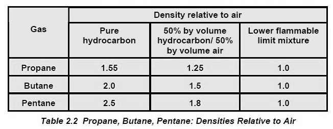
It will be seen that the density of the undiluted gas from a product such as motor gasoline is likely to be about twice that of air, and that from a typical crude oil about 1.5 times. These high densities, and the layering effects that result from them, are only significant while the gas remains concentrated. As it is diluted with air, the density of the gas/air mixture from all three types of cargo approaches that of air and, at the lower flammable limit, is indistinguishable from it.
-
 2nd Mate (F.G.) & NCV (NWKO) – Volume 3 (Cargo)₹ 219.00
 -
 Cargo Consolidated Notes for Phase 1 Chief Mate₹ 361.00
 -
 Cargo Solved MMD Past Papers Phase 1 Chief MatePrice range: ₹ 244.00 through ₹ 576.00