Posted on Leave a comment

Risk Assessment

Risk Assessment of Damage & Control Measures after Stranding:

  • Prior to transiting the HRA, ship operators and Masters should carry out a thorough Risk Assessment to assess the likelihood and consequences of piracy attacks to the vessel, based on the latest available information.
  • The output of this Risk Assessment should identify measures for prevention, mitigation and recovery, which will mean combining statutory regulations with supplementary measures to combat piracy. It is important that the Risk Assessment is ship and voyage specific and not generic.
  • Factors to be considered in the Risk Assessment should include, but may not be limited to, the following:-
    1. Crew Safety – When trying to prevent prate boarding, it must be ensured that crew members will not be trapped inside and should be able to escape in the event of another type of emergency, such as for example fire. A Safe Muster Point or Citadel should be considered. Adequate ballistic protection should be given to the crew who may be required to be on the bridge during a pirate attack, as pirates fire at the Bridge to try to force the ship to stop.
    2. Freeboard – Pirates try to board the ship at the lowest point above the waterline, making it easier for them to climb onboard. These points are often on either quarter or at the vessel’s stern. Experience suggests that vessels with a minimum freeboard greater than 8 metres have a much greater chance of successfully escaping a piracy attempt than those with less. This also depends on the construction of the ship. A large freeboard alone may not be enough to deter a pirate attack.
    3. Speed – One of the most effective ways to defeat a pirate attack is by using speed to try to outrun the attackers and / or make it difficult to board. Ships are recommended to proceed at Full Sea Speed or maximum safe speed throughout their transit of the HRA. If a vessel is part of a ‘Group Transit’ within the IRTC, speed may be required to be adjusted.
    4. Sea State – Pirates mount their attacks from very small craft (skiffs), even where they are supported by ‘Motherships’, which tends to limit their operations to moderate sea states. It is difficult to operate small craft effectively in sea state 3 and above.
Posted on Leave a comment

Muster List

Muster List

Emergency planning of the ship and onboard training are closely related.  The ship’s crew is divided into teams and all are allocated duties to perform in response to emergencies and to ensure personnel safety.  On board ship this is achieved through muster lists.

All ships engaged on international voyages and ships of Classes II(A) and III must have muster lists.  It is the duty of the Master of the ship to compile the muster list and keep it up to date.  Copies of the muster list must be exhibited in conspicuous places throughout the ship and must be exhibited in the wheelhouse, engine room and crew accommodation.

The format of muster lists is usually prepared by the company under the SMS.  For ships of Classes I, II, II(A) and III, the muster list should be approved by the Flag State Administration (MCA in the case of the UK).

The following is an example of a muster list.

MUSTER LIST – PART A

Name of vessel:……………………………………………………..

Emergency SignalDescription of Signal
General emergency alarmSeven or more short blasts/rings followed by one long on vessel’s whistle and internal bells
Withdraw to boats/raftsSeries of long blasts/rings on vessel’s whistle and internal bells
Abandon shipVerbal command from Master or Officer in Charge
Man overboardThree long blasts on vessel’s whistle, repeated as necessary.  This signal may be supplemented as required on internal bells and/or public address announcement
Automatic fire alarmContinuous ringing of internal bells
Emergency SignalAction on Hearing Signal
General emergency alarmAll crew proceed to their emergency station, wearing suitable and sufficient clothing, footwear and protective headgear, carrying lifejacket, survival suit and hand-held VHF radios (where allocated), closing all doors behind them as they go.  Team Leaders check off personnel and report to Bridge Team.  Bridge Team ensures automatic fire doors closed (where fitted) and ventilation stopped (as appropriate).  Specific duties are defined in Muster List – Part B.  Additional duties will be allocated depending upon the nature of the emergency.
Withdraw to boats/raftsAll crew proceed immediately to their allocated boat/raft station, donning survival suits and lifejacket.  Master or Officer in Charge arranges distribution of GMDSS VHF radios, SARTs, EPIRT and vessel’s current position.
Abandon shipAll survival craft launched, followed by evacuation of crew.
Man overboardMaster and deck officers to wheelhouse.  Chief Engineer and motorman to engine control room.  All other crew to their emergency station.  (Refer to appropriate ship contingency plan)
Automatic fire alarmDuring unmanned operation, either at sea or in port, protected space to be examined by two persons including a responsible officer.  During manned operation, bridge or duty deck officer to be advised immediately of the situation.  General emergency alarm shall thereafter be activated if the fire confirmed, or at any time if there is doubt as to the safety of the vessel or crew.
Emergency StationLocation for Muster
Bridge TeamWheelhouse
Engine Room TeamLocation
Deck TeamLocation
Back-up TeamLocation

The Second Officer is responsible for ensuring that all life-saving appliances (LSA) and portable fire fighting equipment (FFE) are maintained in good condition and ready for immediate use.  The Chief Engineer is responsible for ensuring that all fixed fire fighting equipment (FFE) is maintained in good condition and ready for immediate use.  Any deficiencies and/or defects discovered must be reported to the appropriate officer immediately.

All crew members must familiarise themselves with the content of the vessel’s muster list (Parts A and B) and with their emergency duties assigned therein before the commencement of each voyage.  All officers must familiarise themselves with the content of Shipboard Contingency Plans.

Any member of crew unsure as to the content of the muster list and/or their duties must consult a superior officer.

Posted on Leave a comment

Contingency Planning

Composition of Emergency Teams in the Contingency Plan:

  1. The Command Team – will be on the Bridge ( called Command Center) and take overall charge of all operations. Hence, frequent feedback, short and crisp, is necessary from each team to the Command Center. Navigation, communication, maintenance of records of all actions and their timings, etc. will be carried out at the Command Center.
  2. The Emergency Team – would be divided into two, depending on the emergency. Where the emergency is in the E/R, the second engineer will be the leader of the Primary Team and Chief Officer will lead the back-up team. If the emergency is elsewhere, the Chief Officer will be the leader of the Primary team and the Second Engineer will lead the backup team.
  3. The Support Team – also called the medical team, will look after administration of first aid, if and when required. They will prepare the patients for evacuation, prepare lifeboats in case of necessity to abandon the ship,  shut watertight doors and vents, provide assistance to other teams as directed by the Command Team, etc.
  4. Engine Room Team – also called Roving Team, will be under the charge of Chief Engineer. They will attend to E/R systems, services and controls, start emergency fire pump when required, isolate electricity from compartments on fire, shut off ventilation systems to compartments on fire and provide assistance to other teams as directed by the command team.
  5. Crew for Rescue Boat – This team is mainly for man overboard or for picking up survivors from the water. They will prepare the rescue boat and on specific instructions from the command team, lower and launch the rescue boat, rescues the man or survivors and get hoisted back on board.

IMO for preparing Contingency Plans for Various Emergencies:

All crews are familiar with a system of procedures and guidelines for performing potentially hazardous and safety related operations.  For example:

  • Entry into enclosed spaces.
  • Actions after collision.
  • Abandonment.

The majority of these procedures and guidelines have been well documented in publications such as the Code of Safe Working Practises for Seamen, SOLAS, MARPOL, MGNs etc.  However they relied on the Master, officers and crew remembering them from their studies.  The additional problem lay with them being ‘generic’ rather than vessel-specific.  Other procedures were developed from the experience of the Master on board at a particular time, which caused confusion amongst officers and crews when the Master was relieved.

This was one of the reasons for the introduction of ISM and, in particular, the vessel’s SMS.

Since 1 July 2002 all vessels of 500 gross tonnes and above must carry a SMC and will be the subject of internal and external audits to verify that the documented procedures are being followed.  It is true to say that a large number of companies delayed the production and subsequent approval of their SMSs until very close to the implementation date.

Company SMSs were developed utilising a range of resources, for example quality managers appointed from both within the company and externally, consultancy companies and ‘off the shelf’ SMS models.  This led to a proliferation of differing methods for producing SMSs and the ways in which they were presented, particularly at shipboard level.

The Maritime Safety Committee (MSC) of the International Maritime Organisation (IMO) identified this as a problem area and stated that they were “concerned that the presence on board ships of different and non-harmonized emergency plans may be counter-productive in case of an emergency” hence the adoption of Resolution A.852(20), on 27 November 1997, of Guidelines for a Structure of an Integrated System of Contingency Planning for Shipboard Emergencies.

These guidelines will be the basis for your study in preparing emergency and damage control plans.  They may vary from the system on board your vessel/s but the essential elements will be similar, namely : Planning, Preparing, Training, Response actions, Reporting.


Posted on Leave a comment

Squat

Description Method of Calculation & Application:

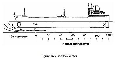
  • In figure 6-3 the ship is running on even keel with a small under keel clearance and, therefore, water which would normally pass under the ship is now severely restricted.
Squat - Shallow Water

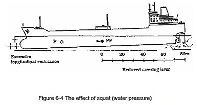
This result in two things, firstly the build of water ahead of the ship, longitudinal resistance pushes the pivot point back from P to PP and the steering lever is reduced. Secondly the water being forced under the bow, at a higher speed than normal, creates a low pressure and loss of buoyancy. The ship will now ‘Squat by the Bow’ which in turn makes the problem even worse. Several cases have been reported of large ships running in shallow water and experiencing bow sinkage of up to 2 metres!

Squat - The effect of Squat (water pressure)

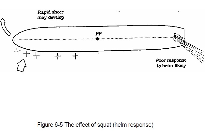
In addition to the possibility of grounding forward there also exists the possibility of losing control and sheering violently out of a channel. If the helmsman allows a small swing to develop, longitudinal resistance ahead of the ship will be brought round onto the exposed bow, (as in figure 6-5) which in turn will encourage a violent swing in the same direction as the helm. Counter helm to correct the swing may be sluggish because as we have seen, the steering lever is reduced. Once the ship does respond, it may now sheer violently the other way. A chain reaction then sets in, with the ship sheering badly from one side to the other and failing to respond correctly to the helm. The effect can be extremely rapid, with the ship out of the channel and aground in just a few minutes. Excessive speed is the main contributing factor under such circumstance; reduced speeds are essential to avoid such violent forces building up.

Squat - The effect of Squat (helm response)
  • Trim is also important and in some districts the pilotage authority may refuse to handle certain ships if they are trimmed by the head and may even request a small trim by the stern. The latter does, in any case, improve the steering lever and therefore the handling of a ship, it may also be intended as an allowance for squat by the bow and very much a decision based upon local knowledge and experience.

Effect:-

  • Water displaced by the hull is not easily replaced.
  • Bow wave and stern wave increase in height.
  • Trough becomes deeper and after part is drawn downwards.
  • Under keel clearance decreases.

Squat varies on the following factors:-

Ship’s speed: – Squat is directly proportional to the square of speed.

                                                Squat a V2 (V = speed in knots)

Block co-efficient: – Squat directly varies with CB.

                                                Squat a CB

Blockage factor (S):- it is the ration between cross section of the vessel and cross section of the canal or river. Squat varies with blockage factor as.

                                                Squat a S0.81

So, in confined water, squat is more than in open water.

Squat may be calculated by the following simplified formulae:

                                                Squat = (CB X V2) / 100                        (In open waters)                     

                                                Squat = 2 X (CB X V2) / 100                  (In confined waters)


Posted on Leave a comment

Navigation in Ice

Preparations & Precautions while Navigating in Ice:

  1. A large area of floating ice formed over a period of many years and consisting of pieces of ice-driven together by wind, current, etc. also called as ice-pack.
  2. Ice is an obstacle to any ship, even an ice-breaker, and the inexperienced navigation officer is advised to develop a healthy respect for the latent power and strength of ice in all its forms.
  3. However, it is quite possible, and continues to be proven so far well-found ships in capable hands to navigate successfully through ice-covered waters.
  4. The first principle of successful ice-navigation is to maintain freedom of man oeuvre.
  5. Once, a ship becomes trapped, the vessel goes where-ever the ice goes.
  6. Ice Navigation requires great patience and can be a tiring business with or without ice-breaker escort.
  7. Experience has proven that in ice of higher concentration, four basic ship-handling rules apply :
    • Keep moving – even very slowly, but try to keep moving,
    • Try to work with the ice-movement,
    • Excessive speed almost always results in ice damage,
    • Know your ship’s manoeuvring characteristics.
  8. Navigation in pack ice after dark should not be attempted without high-power search-lights which can be controlled easily from the bridge.
  9. In poor visibility, heave to and keep the propeller turning slowly as it is less susceptible to ice damage than if it were completely stopped.
  10. Propellers and rudders are the most vulnerable parts of the ship, ship’s should go astern in ice with extreme care – always with the rudder amid-ship.
  11. All forms of glacial ice / ice-bergs, bergy bits, growlers in the pack should be given a wide berth, as they are current driven whereas the pack is wind driven.
  12. When a ship navigating independently becomes beset, it usually requires ice-breaker assistance to free it. However, ships in ballast can sometimes free themselves by pumping and transferring ballast from side-to-side, and it may require very little change in trim or list to release the ship.
  13. Masters who are in-experienced in ice often find it useful to employ the services of an ice-pilot / advisor for transiting the Gulf of St. Lawrence in winter or an Ice-navigator for voyages into the Arctic in the summer.

Posted on Leave a comment

IAMSAR Introduction

The purpose of the International Aeronautical and Maritime Search and Rescue Manual for Mobile Facilities, which is intended for carriage aboard search and rescue units, and aboard civil aircraft and vessels, is to provide guidance to those who:

* operate aircraft, vessels or other craft, and who may be called upon to use the facility to support SAR operations

* may need to perform on-scene coordinator functions for multiple facilities in the vicinity of a distress situation

* experience actual or potential emergencies, and may require search and rescue (SAR) assistance.

Responsibilities and Obligations to Assist:

Under long-standing traditions of the sea and various provisions of international law, ship masters are obligated to assist others in distress at sea whenever they can safely do so.

The responsibilities to render assistance to a distressed vessel or aircraft are based on humanitarian considerations and established international practice. Specific obligations can be found in several conventions, including the following:

· Annex 12 to the Convention on International Civil Aviation

· International Convention on Maritime Search and Rescue

· Regulation V/1 0 of the International Convention for the Safety of Life at Sea, 1974 (SOLAS 1974). (See appendix A).


National and Regional SAR System Organization:

Many States have accepted the obligation to provide aeronautical and maritime SAR co-ordination and services on a 24-hour basis for their territories, territorial seas, and where appropriate, the high seas.

• To carry out these responsibilities, States have established national SAR organizations, or, joined one or more other States to form a regional SAR organization associated with an ocean area or continent.

• A search and rescue region (SRR) is an area of defined dimensions associated with a rescue co-ordination center (RCC) within which SAR services are provided.

1. SRRs help to define who has primary responsibility for coordinating responses to distress situations in every area of the world, but they are not intended to restrict anyone from assisting persons in distress

2. the International Civil Aviation Organization (ICAO) regional air navigation plans (RANPS) depict aeronautical SRRs 3. the International Maritime Organization (IMO) Global SAR Plan depicts maritime SRRS.


Search and Rescue Region (SRR) and its purpose:

A Search and Rescue Region (SRR) is an area of defined dimensions associated with a rescue co-ordination centre (RCC) within which SAR services are provided.

Purpose:-

  • SRRs help to define who has primary responsibility for co-ordinating responses to distress situations in every area of the world, but they are not intended to restrict anyone from assisting persons in distress.
  • The International Civil Aviation Organization (ICAO) regional air navigation plans (RANPs) depict aeronautical SRRs.
  • The International Maritime Organization (IMO) Global SAR Plan depicts maritime SRRs.

SAR co-ordination to be carried out on the scene of distress in search and Rescue operation:

SAR Co-ordination:

The SAR system has three general levels of co-ordination:

  • SAR co-ordinators (SCs)
  • SAR mission co-ordinators (SMCs)
  • On-scene co-ordinators (OSCs).
  • SAR Co-ordinators:
    • SCs are the top level SAR managers; each State normally will have one or more persons or agencies for whom this designation may be appropriate.
    • SCs have the overall responsibility for:
      • Establishing, staffing, equipping and managing the SAR system.
      • Establishing RCCs and rescue sub-centres (RSCs).
      • Providing or arranging for SAR facilities.
      • Co-ordinating SAR training.
      • Developing SAR policies.
  • SAR Mission Co-ordinator:
    • Each SAR operation is carried out under the guidance of an SMC. This function exists only for the duration of a specific SAR incident and is normally performed by the RCC chief or a designee. The SMC may have assisting staff.
    • The SMC guides a SAR operation until a rescue has been effected or it becomes apparent that further efforts would be of no avail.
    • The SMC should be well trained in all SAR processes, be thoroughly familiar with the applicable SAR plans, and:
      • Gather information about distress situations.
      • Develop accurate and workable SAR action plans.
      • Dispatch and co-ordinate the resources to carry out SAR missions.
    • SMC duties include:
      • obtain and evaluate all data on the emergency
      • ascertain the type of emergency equipment carried by the missing or distressed craft
      • remain informed of prevailing environmental conditions
      • if necessary, ascertain movements and locations of vessels and alert shipping in likely search areas for rescue, lookout and/or radio watch
      • plot the areas to search and decide on methods and facilities to be used
      • develop the search action plan and rescue action plan as appropriate
      • co-ordinate the operation with adjacent RCCs when appropriate
      • arrange briefing and debriefing of SAR personnel
      • evaluate all reports and modify search action plan as necessary
      • arrange for refuelling of aircraft and, for prolonged search, make arrangements for the accommodation of SAR personnel
      • arrange for delivery of supplies to sustain survivors
      • maintain in chronological order an accurate and up-to-date record
      • issue progress reports
      • determine when to suspend or terminate the search
      • release SAR facilities when assistance is no longer required
      • notify accident investigation authorities
      • if applicable, notify the State of registry of the aircraft
      • prepare a final report.
  • On-Scene Co-ordinator:
    • When two or more SAR facilities are working together on the same mission, one person on-scene may be needed to co-ordinate the activities of all participating facilities.
      • The SMC designates an OSC, who may be the person in charge of a:
      • Search and rescue unit (SRU), ship, or aircraft participating in a search, or
      • Nearby facility in a position to handle OSC duties.
    • The person in charge of the first facility to arrive at the scene will normally assume the OSC function until the SMC arranges for that person to be relieved.

Also Check out:-

Man overboard preferred Manouevre

IAMSAR Search Pattern


Posted on Leave a comment

Towing

GUIDELINES FOR EMERGENCY TOWING ARRANGEMENTS ON TANKERS:

1. PURPOSE:

1.2 The present Guidelines are intended to provide standards for the design and construction of emergency towing arrangements which Administrations are recommended to implement.

1.3 For existing tankers fitted with the emergency towing arrangements in accordance with resolution A.535 (13), the existing towing arrangements forward of the ship may be retained, but the towing arrangements aft of the ship should be upgraded to comply with the requirements of the present Guidelines.

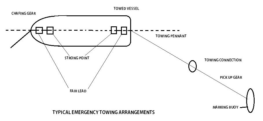
Typical Emergency Towing Arrangements

2. REQUIREMENTS FOR THE ARRANGEMENTS AND COMPONENTS:

2.1 General:

The emergency towing arrangements should be so designed as to facilitate salvage and emergency towing operations on tankers primarily to reduce the risk of pollution. The arrangements should at all times be capable of rapid deployment in the absence of main power on the ship to be towed and easy connection to the towing vessel. Figure shows arrangements which may be used as reference.

2.2 Towing Components:

 Forward of Ship*Aft of Ship*Strength Requirements
Pick-up gearOptionalYes
Towing PennantOptionalYesYes
Chafing gearYesDepending on designYes
FairleadYesYesYes
StrongpointYesYesYes
Rolling PedestalYesDepending on design

The major components of the towing arrangements should consist of the following:

2.3 Strength of the towing components:

2.3.1 Towing components as specified in 2.2 for strength should have a working strength of at least 1,000 kN for tankers of 20,000 tonnes deadweight and over but less than 50,000 tonnes deadweight and at least 2,000 kN for tankers of 50,000 tonnes deadweight and over(working strength is defined as one half ultimate strength). The strength should be sufficient for all relevant angles of towline, i.e. up to 90° from the ship’s centerline to port and starboard and 30° vertical downwards.

2.3.2 Other components should have a working strength sufficient to withstand the load to which such components may be subjected during the towing operation.

2.4 Length of towing pennant:

The towing pennant should have a length of at least twice the lightest seagoing ballast freeboard at the fairlead plus 50 m.

2.5 Location of strongpoint and fairlead:

The bow and stern strongpoint and fairleads should be located so as to facilitate towing from either side of the bow or stern and minimize the stress on the towing system.

2.6 Strongpoint:

The inboard end fastening should be a stopper or bracket or other fitting of equivalent strength. The strongpoint can be designed integral with the fairlead.

2.7 Fairleads:

2.7.1 Size:

Fairleads should have an opening large enough to pass the largest portion of the chafing gear,   towing pennant or towing line.

2.7.2 Geometry:

The fairlead should give adequate support for the towing pennant during towing operation which means bending 90°to port and to starboard side and 30°vertical downwards. The vending ratio (towing pennant bearing surface diameter to towing pennant diameter should be not less than 7 to 1.)

2.7.3 Vertical location:

The fairlead should be located as close as possible to the deck and, in any case, in such a position that the chafing chain is approximately parallel to the deck when it is under strain between the strongpoint and the fairlead.

2.8 Chafing Chain:

Different solutions on design of chafing gear can be used. If a chafing chain is to be used, it should have the following characteristics:

2.8.1 Type

The chafing chain should be stud link chain.

2.8.2 Length

The chafing chain should be long enough to ensure that the towing pennant remains outside the fairlead during the towing operation. A chain extending from the strongpoint to a point at least 3 m beyond the fairlead should meet this criterion.

2.8.3 Connecting limits

One end of the chafing chain should be suitable for connection to the strongpoint. The other end should be fitted with a standard pear-shaped open link allowing connection to a standard bow shackle.

2.8.4 Stowage

The chafing chain should be stowed in such a way that it can be rapidly connected to the strongpoint.

2.9 Towing connection

The towing pennant should have a hard eye-formed termination allowing connection to a standard bow shackle.

2.10 Prototype test

Designs of emergency towing arrangements in accordance with these Guidelines should be prototype tested to the satisfaction of the Administration.

3. READY AVAILABILITY OF TOWING ARRANGEMENTS:

3.1 To facilitate approval of such equipment and to ensure rapid deployment, emergency towing arrangements should comply with the following criteria:

3.1.1 The aft emergency towing arrangement should be pre-rigged and be capable of being deployed in a controlled manner in harbour conditions in not more than 15 min.

3.1.2 The pick-up gear for the aft towing pennant should be designed at least for manual operation by one person taking into account the absence of power and the potential for adverse environmental conditions that may prevail during such emergency towing operations. The pick-up gear should be protected against the weather and other adverse conditions that may prevail.

3.1.3 The forward emergency towing arrangement should be capable of being deployed in harbour conditions in not more than 1 h.

3.1.4 The forward emergency towing arrangement should be designed at least with a means of securing a towline to the chafing gear using a suitably positioned pedestal toller to facilitate connection of the towing pennant.

3.1.5 Forward emergency towing arrangements which comply with the requirements for aft emergency towing arrangements may be accepted.

3.1.6 All emergency towing arrangements should be clearly marked to facilitate safe and effective use even in darkness and poor visibility.

3.2 All emergency towing components should be inspected by ship personnel at regular intervals and maintained in good working order.


Tractor Tug:

Tractor Tugs: The design of tractor tugs is unlike that of conventional tugs. The propulsion units are fully turning controllable pitch blades, able to give thrust in any direction and act as steering units or azimuthing fixed or controllable pitched propellers. The propulsion units are placed far ahead of the towing point, close to the pivot point thereby producing a large turning momentum. This potentially gives a poor steering performance, which is overcome by fitting a large centreline skeg. Their general characteristics are:

  • Full power available in all directions
  • Quick response to engine movements.
  • Very maneuverable, especially in tight sea space.
  • Reduced risk of girting / girding.
  • Reduced maneuverability if towing from forward at higher speeds.
  • Reduced directional stability, particularly in open waters.
  • Reduced bollard pull per kilowatt output.
  • Relatively deeper in draught therefore increased risk of bottom damage from grounding.
  • Increased training required for tug masters.


Tow Plan:

Planning and preparation before a Tow commences might include:

  • Assessing the size and type of vessels or barges to be towed and any limitations of the tow.
  • Confirmation that the tug is of suitable; size, manning, sea-keeping, horse power (HP) and bollard pull (BP).
  • Tow wire and towing equipment is suitable for the planned tow.
  • Route to be taken and passage planned, including safe transit times (day/night transits), times when passing through narrows, under bridges or areas of high traffic density, tight bends in rivers and adjacent river berths.
  • Noting: and areas of reduced depth, tidal limitations and currents expected during the voyage.
  • A list of bridges with maximum and minimum height; tide height for each arch to be passed under showing the bridge’s maximum air-drafts.
  • Weather forecasts to include outlook for at least 48 hours.
  • Confirmation of sufficient fuel, water, spares on board.
  • Navigational information and warnings.
  • Recommended speeds to comply with river regulations.
  • Connection and disconnection arrangements.
  • Stability of the tug and towed unit.
  • Emergency contingency plans.

Preparations on board the Tug:

It is essential that checks should be completed on board the tug and vessel or barge to be towed, which should include:

  • All water / weathertight openings are securely closed with signs indicating that they should remain closed for the duration of the voyage. It is a reality that tugs have capsized as a result of doors and ports being left open when in difficulty, e.g. girting. Down flooding is a real danger to small tugs.
  • Life-saving and fire-fighting appliances must always be operational.
  • Navigational equipment, wheelhouse whistles, horns, shapes for day signals and communication gear are fully operational.
  • All critical machinery prior to commencing a towing operation should be confirmed as operational – this would include; main engine, steering gear and towing equipment (winches, wires) etc.
  • All personnel are fully familiar with the intended towage plan and their responsibilities.
  • Any change of fuel and ballast to the tug and/or tow have been fully calculated and the crew are aware of any factors of concern.

Checks on board the towed vessel or barge:

The tow should not proceed until a satisfactory inspection of the tow has been carried out by a competent party.

Checks should include:

  • Condition of the towing arrangements
  • Condition of the anchoring equipment if fitted. If not fitted some authorities require a temporary anchor to be supplied of an adequate weight.
  • Condition of tow including an inspection of the peaks and buoyancy spaces to check for water ingress.
  • Watertight integrity of the unit to be towed; obvious signs of damage, especially in the hull and deck plating. Hatchways, ventilators, doors, scuttles, manholes and other openings are closed and sea valves shut.
  • Fore and aft drafts, appropriate freeboard for the voyage and no evidence of a list. Generally a slight trim by the stern ensures that the tow is laterally stable when towed.
  • Air draft of the tow, appropriate for the voyage and bridge transits.
  • Power is available for navigation lights.
  • Safe method of boarding available (portable or fixed rungs).
  • Emergency towline rigged.
  • Life-saving and fire-fighting appliances are in good condition and in the regulatory number required.
  • Cargo, whether it is bulk cargo (within the holds), containers or break bulk cargo can shift causing the barge to capsize and sink and therefore stowage and securing arrangements must be verified as adequate for the intended voyage prior to departure.
  • Some bulk cargoes pose a serious hazard, including spoil and certain ore cargoes which are liable to liquefaction e.g. spoil cargoes can contain a high amount of moisture which can assume a liquid state in a seaway and can cause the barge to lose stability, list and even capsize.
  • Reference should be made to the IMO International Maritime Solid Bulk Cargoes (IMSBC Code). When it is suspected that cargoes with high moisture content have been loaded onto a barge advice should be sought.
  • If cargo is liable to move e.g. vehicles and timber, the lashing arrangements and sea fastenings should be inspected.
Posted on Leave a comment

Master – Pilot Information Exchange

Navigation with Pilot on Board:

  • Immediately on arrival in bridge, Pilot to be informed of ship’s heading, speed, engine setting and draft.
  • Master pilot exchange to be carried out.
  • Pilot informed of LSA provided on bridge, discuss about any ISPS requirement if any.
  • Completed Pilot Card handed to pilot.
  • Pilot referred to Wheelhouse Poster.
  • Familiarization of bridge and communication systems to be given to pilot.
  • Discuss about status of anchors.
  • Any other relevant procedures / checklist as per SMS to be complied with.
  • Details of proposed passage plan discussed with the pilot and agreed with the master including: UKC, radio communications and reporting requirements.
  • Discuss about the watchkeeping arrangement and crew stand by arrangements including tose who are stand by forward, discuss about abort points and contingency anchorages.
  • Responsibilities within the bridge team for the pilotage defined and clearly understood.
  • Discuss about requirement of local regulation including hoisting of a flag, shape of exhibition of light etc.
  • Discuss about the following:-
    • Configuration of ropes (fwd & aft.)
    • Which line to be the first line (fwd & aft.)
    • Any mooring boat available
    • How many tugs & points where these tugs to be fast, power of the tugs (bollard pull etc), what time tugs expected in order to give notice to ship staff.
  • Lighting arrangement for stations must be consulted prior to switching on lights especially for fwd stn (lights preferably facing fwd).
  • Discuss about information related to berthing / anchoring arrangements.
  • Discuss about expected traffic during transit, pilot change over arrangements, fender requirements. Discuss about instructions for pilot ladder / accommodation ladder.
  • Watchkeeping level to be as per company’s SMS.
  • Progress of the ship and execution of orders being monitored by the master and OOW, position fixing to be done as per position plotting interval as ordered by Master, Parallel indexing technique to be used as and when possible.
  • Traffic situation to be monitored, keep eye on all the vessels in the vicinity and data pertaining to CPA, TCPA, range, bearing, bow crossing range, bow crossing distance. Good look out to be maintained, long range scanning to be done to detect the object in ample time.
  • Comply with COLREGS/ local regulations, effectiveness of action to be checked.
  • UKC to be monitored.
  • Any instruction as per Masters standing orders, bridge orders to be complied with.
  • VTS to be reported (normally done by pilot), VHF to be maintained on required frequencies.
  • E/R and ship’s crew regularly briefed on the progress of the ship during pilotage.
  • Arrangement to relieve officers, helmsman, look out, and those stand by for anchor party to be done.
  • Ensure Master’s orders and pilot’s advice is complied with.
  • Monitor all the displays on bridge – tachometer, rudder angle indicator, ROTI, anemometer etc, also displays for course steered and course made good, speed through water and speed over ground etc.

Significance of Master Pilot Information Exchange:

  • Navigation Advice to Pilot:
    •  Vessel’s heading, speed, RPM. (speed increasing/ decreasing)
    •  Distance off/ bearing of nearest appropriate navigating/ aid or landmark
    •  ETA at next course change position, next course/ heading
    •  Point out converging and close – by traffic
    •  Depth of water under the keel
    •  Any other items
  • Reach Agreement on Underway Procedures:
    • Manoeuvres for narrows, bends, turns, etc
    • Courses/ headings, distance off danger areas, maximum speed
    • Restrictions: day versus night movement/ berthing
    • Tide and current conditions not acceptable
    • Minimum acceptable visibility at any point
    • Use of anchor (planned, emergency)
    • Manoeuvres not requiring tugs
    • Manoeuvres requiring tugs
    • Number of tugs required (and when)
    • Source of tug securing lines: ship or tug
    • Push/ pull power of required tugs
    • Communications procedure between vessel and tugs
    • Placement of tugs alongside
    • Crew standby requirement – number available and stations
    • Expected time vessel has to arrive at berth/ turning basin at high / low / slack wateraverage
    • Speed to his positions
    • Any other items
  • Reach Agreement on Mooring / Unmooring Procedures:
    •  Maximum acceptable wind force and direction
    •  Unmooring procedures without tugs in event of emergency
    •  Sequence of running out/retrieving-mooring lines / Wires
    •  Mooring lines to be run out by launch and time to run lines
    •  Provision for dock line handlers
    •  Determine which side to
    •  Fire wires required
    •  Any other items

Information to be provided by Pilot

Pilot Mr. _______________ Date ________

Please provide following information to the Master:

  •  Intended navigation plan for the passage.
  •  Speed(s) required at different stages of the passage.
  •  Any navigation restrictions: – Dry versus night navigation etc.
  •  Status of navigational aids in Pilot age waters.
  •  Tides, currents, weather anticipated.
  •  Expected traffic conditions.
  •  Any other information critical to the safe passage.
  •  Contingency plans, alternative routes (if available).
  •  Minimum visibility acceptable at any time.

 Use of critical /anchors (planned or emergency).


Significance of Master-Pilot Information Exchange:

  1. The pilotage passage plan will need to be discussed with the pilot as he comes onboard.
  2. Any amendments to the plan should be agreed and any consequential changes in individual bridge team responsibilities made before pilotage commences.
  3. Where pre-arrival exchange has not taken place extra time and sea room may need to be allowed before pilotage commences under to discuss the plan fully.
  4. The Pilot should be handed over the Pilot Card and shown the Wheelhouse Poster.
  5. The Wheelhouse Poster provides a summary of ship manoeuvring information. A manoeuvring booklet, containing more detailed information may also be available on the bridge.
  6. The pilot has specialised knowledge of navigation in local waters.
  7. The master may delegate the conduct of the ship to the Pilot who directs the navigation in close co-operation with the Master and / or the OOW.
  8. It is important that the responsibilities of the master and the Pilot are clearly understood.
  9. The pressure of a pilot does not relieve the master or the OOW of their duties or obligations for the safety of a ship.
  10. Both should be prepared to exercise their right not to proceed to a point where the ship would not be to maneuvering or would be in danger.
  11. The safe progress of the ship along the planned tracks should be closely monitored at all times which includes regular position fix, monitoring underkeel clearance.
  12. Verbal orders from the pilot also need to be checked to confirm that they have been correctly carried out.
  13. This includes monitoring both the rudder angle and RPM indicator when helm and engine orders are given.
  14. OOW should always seek clarification from the pilot when in doubt of pilot actions or intentions. If a satisfactory explanation is not given, he should notify the Master immediately.

Posted on Leave a comment

Cargo Related Documents Carried on Bulk Carrier

Below is the list with short description of all the possible certificates and documents which are related to cargo expected to be carried in a bulk carrier:-

1. Hold inspection certificate: The hold or hatch inspection certificate, or preloading survey certificate, is issued by a surveyor after inspecting the holds to ensure that they are suitable for the intended cargo.

A preloading survey is required when the local authorities at the loading port or the shipper demand it or when it is a charterparty requirement. When a survey is required, loading cannot commence in a hold until the surveyor has passed it. Often the vessel cannot present notice of readiness until the hold inspection certificate has been issued. If any holds fail the survey, a vessel on time charter may be placed off hire and a vessel on voyage charter may fail to start time running against charterers until such time as the holds have been resurveyed and passed, although it may be possible to have some holds passed so that the vessel can submit a valid notice of readiness and/or commence to load in suitable holds.

The surveyor will provide the hold inspection certificate for whoever instructs him, but a copy will normally be given to the Master. The Master has no powers, except the power of reason, to require the surveyor to alter a negative conclusion. But if the Master considers that the surveyor’s conclusions are unreasonable and if the consequences are likely to be costly, the Master can set out his views in writing in a letter of protest or he can obtain services of another surveyor, perhaps with the help of the ship’s P&I club. A second surveyor cannot overrule the first, but can provide evidence of the facts for use in a dispute.

2. Mate’s receipt: A mate’s receipt is usually a printed form, often with handwritten entries which acknowledges on behalf of the ship the receipt of the goods. It is evidence that the goods specified in it have been delivered to and received by the ship (It is signed by chief officer of the receiving ship). Usually the person to whom the mate’s receipt is given is the person entitled to a bill of lading in exchange for the return of the mate’s receipt. 

When any damaged or deficient cargo is delivered to the ship it should immediately be brought to the attention of the shippers or their agents so that it can be removed and undamaged cargo supplied in its place. This requirement should be confirmed in writing to provide a record in the event of a dispute. Alternatively, clausing (qualifying words) can be inserted to describe the condition of the goods at the time of delivery. As it is a common requirement that bills of lading should be issued in accordance with mate’s receipts, if damaged cargo is not removed it will be necessary to clause the mate’s receipt which will then lead to clausing of the bill of lading.

3. Authorization to sign Bills of Lading: Under the terms of many time and voyage charterparties the owners transfer the authority to sign bills of lading to the charterers or their agent, thereby cancelling the authority normally held by the Master. In any case in which the agent will be signing bills of lading on behalf of the Master, the master should ensure that the agent receives appropriate instructions in the form of authorization. The wording of any such authorization is often dictated by owners or charterers voyage instructions.

4. Bills of Lading: A bill of lading may perform three functions. (A)It is usually very good evidence of the terms of the contract for the receipt, carriage and delivery of the cargo.(B)It is often a negotiable document of title to goods carried, providing evidence of ownership of the cargo, and(C)it acts as a receipt of cargo loaded aboard the vessel.

5. Phytosanitary Certificate:  This certificate may be required during the carriage of plant or plant products like, grain, seeds and fruits. Phytosanitary certificates are issued by inspectors in the exporting country to certify the requirement of the plant health regulations of the importing country has been met.

6. Certificate of compliance with exemptions to trade sanctions: When trade sanctions have been imposed on a country, it may still be allowed to import certain commodities such as food and medicines. Ships carrying such exempted cargoes are required to produce a certificate of compliance to the authorities enforcing the sanctions to demonstrate that cargo qualifies for the exemption. These are issued by the exporting governments .A UN approval certificate is also required with this certificate.

7. UN approval certificate: It is a letter from a UN official to the government of a country which proposes to export exempted goods to a country which the subject of UN sanctions. The letter states that the prohibitions in respect of these shipments no longer apply and that the captains of the ships engaged in the trades should be provided with copies of the letter. This letter is provided so that it can be produced to the naval ships operating the blockades against country against whom sanctions are in force.

8. Certificate of origin: It may be required for a cargo, when the authorities in the destination port are applying against another country and require to be satisfied that the cargo does not originate there, or where the origin of cargo must be documented as per the sale contract. This certificate is often issued by a government department, stating the country of origin of the cargo. In some cases authorities will accept ship’s cargo manifest as evidence of the origin of the cargo.  

9. Declaration by shipper: It is made in compliance with the requirement of SOLAS that before loading the shipper should provide to the Master details of any bulk cargo, so that Master can make decisions such as trim of cargo and safety precautions to be observed with respect to the loading and carriage of the cargo. 

10. Certificate of transportable moisture limits: The transportable moisture limit of the cargo which may liquefy is the maximum safe moisture content of the cargo when carried in a bulk carrier. Practically, this figure is normally included in the declaration by shipper.

11. Certificate of moisture content: The moisture content of a sample of cargo is the quantity of water, ice or other liquid which the sample contains, expressed as a percentage of total wet mass of that sample. In practice this figure is included in the shipper’s declaration. If the moisture content is higher than the transportable limit, the cargo may liquefy and cause the ship to become unstable. 

12. Master’s response sheet: This document is issued by some coal shippers to encourage Masters to comply with the General Requirement 15 of the coal section of IMSBC code. This states:’ If the behavior of the cargo during voyage differs from that specified in the declaration by shipper, the Master should report such differences to the shipper. Such report will enable the shipper to maintain records on the behavior of the coal cargoes, so that the information provided to the Master can be reviewed in the light of transport experience.’ The Masters are encouraged to complete and return these to report any unexpected experiences with coal cargoes.

13. Certificate of lashing: The Master may be required to sign a certificate of lashing to state that the securing of a timber deck cargo or a cargo steel coils or other cargo which requires lashing has been to his satisfaction. After signing the certificate the Master retains one copy and other copies are given back to the foreman responsible for the lashing.

14. Certificate of readiness to load: This certificate is issued by the marine authorities in respect of cargoes of grain and concentrates and timber deck cargo, each of which has special loading requirements. The certificate is issued after satisfactory inspections of cargo spaces and pr-loading calculations and contains reminders of restrictions that must be imposed upon loading.

15. Certificate of fitness to proceed to sea: This follows the certificate of readiness to load, being issued by the marine authorities after satisfactory completion of loading of a cargo of grain or concentrates, or a timber deck cargo. As obvious this certificate records the manner in which the cargo has been stowed and provides reminders of precaution which must be taken during the voyage. It also contains details of the vessel’s draught, trim, weights carried and stability on sailing. 

16. Certificate of Loading: A certificate of loading (bulk grain only)is issued in the USA by the National Cargo bureau to certify that a cargo of bulk grain has been loaded as per USCG regulations. The document is similar to the Canadian certificate of fitness to proceed to sea.

17. Certificate of fumigation: It is issued by the relevant agricultural or other responsible authority and provides the details of the cargo(vegetation and its products cargoes , obviously). A certificate of fumigation is required for two reasons.(A) It will satisfy local the local department of agriculture that the cargo is free of infestation, and (B) It provides the information which enables an authorized chemist to carry out a gas free test.

A clearance certificate is issued by the chemist when tests show that the residual fumigant has been dispersed from cargo spaces. Such certificate is provided by a chemist in the discharge port to ensure that cargo spaces can be safely entered.

18. Certificate of weight and quantity: A certificate of weight and quality is issued by suitably qualified surveyors and samplers and testifies to the quantity of the cargo loaded and to its physical description and analytical specification. In grain trades this is the document on which the mate’s receipt and bill of lading are based.

19. Stowage plan: Also known as Cargo plan or the hold distribution plan shows the commodity, tonnage and/or measurement of cargo in each hold. The plan may be produced by one of the ship’s officers to provide a record of the loading as observed and measured by ship’s personnel, in which case it may also provide information about the bunkers carried and the vessel’s draught, trim and stability. Alternatively, stowage plan may be produced by someone from the loading installation to record the quantities loaded in each hold. A stowage plan provide by shore-based staff will normally show the shore values for the tonnages loaded, regardless of whether or not these are the figures used in the bill of lading.

20. Cargo manifest: A cargo manifest is issued by the shippers in the loading port and is based upon the information contained in the bills of lading. It provides brief details of the ship and the loading and discharge ports and list details of the cargo carried. Details include the B/L numbers, contents, gross weight and freight. Copies of the manifest, if available are retained by the master, who will give copies to the authorities in the discharge port or ports visited en-route, if required.

21. Dangerous cargo manifest: It is issued by the shippers in compliance with the regulations which apply at the loading port. The document states the quantity of hazardous material carried and certifies that it has been properly named, prepared and otherwise in proper condition for bulk shipment. The name and description of the hazardous material as given in the Dangerous cargo manifest should be used to confirm the stowage requirements for the cargo, as stated in the IMSBC code and/or IMDG code. The document will be presented to the Master for his signature, and before signing he should satisfy himself, that the stated quantities and positions are correct and that the cargo has been stowed in accordance with the requirements of the codes.

22. Material safety data sheets: MSDS provide detailed information about hazardous cargoes and stores carried on board. It is a must and is issued by the USA. The data includes the useful information about the health hazards and the other dangers associated with the commodity, protective equipment to use, additional precautions, and emergency and the first aid.

23. Health sealing certificate: Cargo hatches may be sealed to prevent theft of cargo or because the holds have been fumigated and are unsafe to enter. When hatches have been sealed by a shore based organization a certificate recording the fact is usually issued, listing the compartments which have been sealed and the type and serial number of the seal used.

24. Statement of Facts: A statement of facts (SOF), sometimes known as a port log, is prepared by the ship’s agents in each loading and each discharging port. It is intended to provide a full record of the times of those events which may be required for the preparation of laytime statement and which may affect claims for dispatch and demurrage or for offhire.

Following things are detailed in the SOF:

  • Arrival of vessel at pilot station, the anchorage and the berth.
  • Time of pilot boarding and the arrival of tugs.
  • Tendering and receipt of notice of readiness.
  • Clearing of the holds by the pre-loading surveyor.
  • Periods of loading and discharging should be recorded.
  • Times of stoppages with their reasons.
  • Weather which interrupts cargo work and adverse weather noted at any other time.
  • Cargo tonnages, bunker figure and draughts
  • Time of fumigation, and any other delays.
  • Time of sailing.

25. Letter of protest: It is a document used to provide a written record of dispute. The Master should write a letter of protest whenever he considers that shippers, stevedores or any other parties are responsible for an event or circumstance which will cause a loss to the ship. The Master is liable to receive a letter of protest if vessel fails in some way to perform in accordance with charterparty. A letter of protest should be supported by photographs when they are available.

26. Empty hold certificate: When there is any doubt as to the outrun of the cargo-for example, if the receiver is claiming that the cargo has been short-landed, the Master can issue an empty hold certificate. Such a certificate will say that all cargo has been discharged and that the holds have been emptied. The stevedore supervisor will be asked to confirm that there is no cargo remained on board. The Master will keep the original and can give copies to the stevedore who sign it and to the ship’s agent. Some owners instruct Masters to obtain empty hold certificates for every cargo carried as it is considered a safe commercial practice.

27. Trimming certificate/ certificate of loading/ Discharging: This is a document which the Master may be asked to sign to confirm that he is satisfied with the manner in which the cargo has been trimmed.

The certificate of fitness to proceed at sea issued by port warden, coast guard or similar authority also testifies the trimming of cargo, but the trimming certificate is issued by the Master, not the authorities. 

The certificate of loading/discharging goes further and requires the Master or chief mate to state that the cargo has been properly loaded, stowed, trimmed and separations laid according to the signatory’s satisfaction.

28. Stevedores’ time sheet: This normally shows the number of gangs employed, the hatches worked and times and reasons for stoppages. If asked to countersign this document the Master should ensure that it is correct. He should insist on the correction of stevedores’ time sheet when it is inaccurate. Alternatively he can sign ‘for receipt only’.

29. Clean ballast discharge permit: This document is nowadays widely used in many parts of the world. This certificate authorizes the vessel to discharge clean ballast in the port limits and stipulates the conditions which must be observed whilst ballast is being discharged. The permit is issued by the port authority following application from the ship’s agent and a copy has to be posted in ship’s gangway with a record of ‘checks and condition of discharge’.

30. Paint compliance certificate: If holds have been repainted shortly before a cargo of grain or other foodstuffs is to be loaded the shippers may demand to see a compliance certificate issued by an independent laboratory, states that all the materials used to make the paint are approved for the use on surfaces which are in contact with foods.

31. Stevedores damage form:  These documents are issued by Master, to hold stevedores responsible for damage to ship or cargo.

32. Certificate of IMO classification: A certificate of IMO classification of a cargo must be issued to the Master by the shipper before shipment of a cargo which is listed in the IMDG code. This is essential so that he can be ready for correct emergency procedures, if they be necessary. Such a certificate is in the form of standardized dangerous goods bill of lading. Copies of the certificate of IMO classification may be required by the receiver and by the port authority in the port of discharge or the ports visited en route.

33. Certificate of compliance/ IMSBS code fitness certificate:  These certificates, issued by an Administration or classification society on behalf of an administration to every ship constructed since 1st September 1984, state the dry bulk cargoes that the ship is constructed, equipped and permitted to carry. In addition to listing permitted cargoes the certificates or their supporting documents list the conditions that must be satisfied and equipment that must be carried if the certificate is to remain valid. The certificate for the carriage of dangerous goods must be renewed at each periodical survey.

34. Hatch closing certificate: This is issued by an attending surveyor, reports on hatch covers which appear to be in good condition and which have been properly closed, and has provision for recording hatch covers or fittings which appear to be defective, or which have not been properly closed. This appears to be a document used by shippers or charterers who want to ensure that their cargoes are well protected. The Master or chief mate, when countersigning the document can, if necessary, insert a remark rejecting the report.

35. No damage certificate: In some countries, particularly India, the Master will be required to sign  a “ No damage certificate” releasing the stevedores from liability after completion of discharge. The ship may be prevented to sail until the certificate has been signed, in that case Masters can sign the certificate with the endorsement ‘without prejudice’.

Posted on Leave a comment

Emergency Response Procedures for Ships Carrying Dangerous Goods (EmS)

Emergency Response Procedures for Ships Carrying Dangerous Goods (EmS) Guide:

This EmS Guide contains guidance on Emergency Response Procedures for Ships Carrying Dangerous Goods including the Emergency Schedules (EmS) to be followed in case of incidents involving dangerous substances, materials or articles, or harmful substances (marine pollutants), regulated under the International Maritime Dangerous Goods Code (IMDG Code).

The purpose of this Guide is to provide guidance for dealing with fires and spillages (leakages) on board ships involving the dangerous goods listed in the International Maritime Dangerous Goods Code (IMDG Code).

In accordance with the International Safety Management (ISM) Code, all ships, and the companies responsible for their operation, are required to maintain a Safety Management System (SMS). Within the SMS, procedures for responding to potential shipboard emergencies are required. This Guide is intended to assist shipowners, ship operators and other parties concerned with developing such emergency response procedures, which should be integrated into the ship’s contingency plan.

In the event of a fire or spillage incident, initial actions should be carried out in accordance with the shipboard emergency plan. Where dangerous goods are involved, the responses in the emergency plan should be based on this Guide for specific dangerous goods having regard to, inter alia, the type of ship, the quantity and type of packaging of the dangerous goods and whether the goods are stowed on or under deck.

EMS Guide:

  1. The EMS Guide contains guidance an Emergency Response Procedures for ships carrying Dangerous goods including the Emergency schedules to be followed in case of incidents involving dangerous substances materials or articles or harmful substances (marine pollutants), regulated under the IMDG Code.
  2. In accordance with the ISM Code all ships & the companies responsible for their operations are required to maintain a SMS. Within the SMS, procedures for responding to potential shipboard emergencies are required. This guide (EMS Procedure) is intended to assist shipowners, shop operators & other parties concerned with a developing such emergency response procedure, which should be integrated into ships contingency plan.
  3. The EMS guide is divided into two emergency schedules viz, Emergency Schedules for five & Emergency schedules for spillage.

Information contained in EMS Guide:-

  1. Identification of Dangerous goods involved in order that specific EMS. Fire schedules for the cargoes may be consulted and appropriate action taken.
  2. Emergency action and diagnosis.
  3. The guide contains table for emergency related to fire & spillage & is listed under various schedules. Describing procedures for action to be taken in special circumstances.
  4. Appendices – The appendices provide comprehensive information, a list of medicines / drugs and a list of chemicals referred to in this tables.