Posted on

Fire Integrity

Standard Fire Test on the Ship

Standard Fire Test:-

  • A standard fire test is a test in which specimens of the relevant bulkhead or decks are exposed in a test furnace to temperatures corresponding approximately to the standard time-temperature curve in accordance with the test method specified in the FTP Code.
  • The specimen must have an exposed surface of 2.44m width and 2.5m height. In case of decks and ceilings, they must be of 2.44mm width and 3.04m length. When the maximum overall height in practice is to be less than that given above, then the test specimen shall be of the maximum height to be used in practice.
  • Orientation of the test piece shall be maintained. A bulkhead shall be tested vertically and a deck or ceiling shall be tested horizontally.
  • Class A and B Class bulkheads and doors shall be tested from each side.
  • A-Class un-insulated steel bulkheads and decks without openings shall be treated as A-0 and no test is required. All other divisions, including class “A-0” divisions with a structural core of aluminum, are required to be tested.
  • Constructions shall be tested without paint or other superimposed finishes,subject to the approval of the Administration.
  • The specimen being tested should resemble as closely as possible the intended construction and include atleast one joint, where applicable.
  • Temperature thermocouples are placed at various points on the specimen to be tested as per FTP Code. During the test, temperatures are recorded at intervals not exceeding 1 minute.
  • The average temperature of the furnace as derived from the furnace thermocouples shall be monitored and controlled such that it follows the standard time-temperature curve. (This is a smooth curve drawn using furnace temperature points measured at 5m, 10m, 15m, 30m and 60m starting from the initial furnace temperature.)
  • The average temperature rise on the unexposed surface shall be calculated as the average of the rises recorded by the individual thermocouples to check if the specimen complies with the requirement on temperature rise.
  • If there is any flaming seen on the unexposed side, the duration and the location shall be recorded. In cases where it is difficult to identify whether or not there are flames then the cotton-wool pad shall be applied to see if ignition of the pad can be initiated.
  • For all “A” class divisions, including those with doors, the test shall continue for a minimum of 60 min. For all “B” class divisions, including those with doors, the test shall continue for a minimum of 30 min.

Limitations in the use of oils as fuel:

The following limitations shall apply to the use of oil as fuel:

  1. Except as otherwise permitted by this paragraph, no oil fuel with a flashpoint of less than 60°C shall be used.
  2. In emergency generators oil fuel with a flashpoint of not less than 43°C may be used.
  3. The use of oil fuel having a flashpoint of less than 60°C but not less than 43°C may be permitted (e.g., for “feeding the emergency fire pump” s engines and the auxiliary machines which are not located in the machinery spaces of category A) subject to the following:
    • Fuel oil tanks except those arranged in double bottom compartments shall be located outside of machinery spaces of category A.
    • Provisions for the measurement of oil temperature are provided on the suction pipe of the oil fuel pump.
    • Stop valves and/or cocks are provided on the inlet side and outlet side of the oil fuel strainers.
    • Pipe joints of welded construction or of circular cone type or spherical type union joint are applied as much as possible.
    • In cargo ships the use of fuel having a lower flashpoint than otherwise specified, for example crude oil, may be permitted provided that such fuel is not stored in any machinery space and subject to the approval by the Administration of the complete installation.

Non Combustible material:

  • It is the one which neither burns nor gives off flammable vapours in sufficient quantity for self-ignition when heated to approximately 7500C, as indicated in the FTP Code.
  • A & B class divisions shall be constructed of non-combustible materials with the following exceptions:
    • Adhesives and vapour barriers, but they should have low flame spread characteristics.
      • Sealing materials used in penetration systems.
      • Seal for gas/weather/water tight doors.

Special category Spaces:

  • Special category spaces are those enclosed vehicle spaces above and below the bulkhead deck, into and from which vehicles can be driven and to which passengers have access. Special category spaces may be accommodated on more than one deck provided that the total overall clear height for vehicles does not exceed 10 m.
  • In passenger ships carrying more than 36 passengers, the bulkheads and decks of special category spaces shall be insulated to’A-60″ class standard.
  • In passenger ships, indicators shall be provided on the navigation bridge to indicate when any fire door leading to or from the special category spaces is closed.
  • In special category spaces to which any passengers carried can have access, the number and locations of the means of escape shall be to the satisfaction of the Administration. Walkways to the means of escape must be provided with a breadth of at least 600 mm. The parking arrangements for vehicles shall maintain the walkways clear at all times.
  • The ventilation system for special category spaces must be sufficient to provide 10 air changes per hour.
  • An efficient fire patrol system shall be maintained in special category spaces. If an efficient fire patrol system is maintained by a continuous fire watch at all times during the voyage, a fixed fire detection and fire alarm system is not required.
  • Special category spaces shall be fitted with a fixed water-based fire-fighting system with provision of manual operation, which shall protect all parts of any deck and vehicle platform of such spaces. A sufficient number of drainage valves must be provided to ensure complete drainage of the system. Also, means shall be provided to prevent the blockage of drainage arrangements.
  • There are additional requirements for special category spaces of Ro-Ro Passenger ships. For example, CCTV surveillance and a water leakage detection system is required to be fitted to provide an indication to the navigation bridge and to ECR of any leakage through the bow or stern doors which could lead to flooding of special category spaces or ro-ro spaces.

Posted on

Torsional Stress

Q) Write short notes on Torsional Stress on ships.

Ans:- Torsional Stress on ships:

  • When a body is subject to a twisting moment which is commonly referred to as torque, that body is said to be in ‘torsion’. A ship heading obliquely (45°) to a wave will be subjected to righting moments of opposite direction at its ends twisting the hull and putting it in ‘torsion’.
  • In most ships, these torsional moments and stresses are negligible but in ships with extremely wide and long deck openings they are significant. A particular example is the larger container ship where at the topsides a heavy torsion box girder structure including the upper deck is provided to accommodate the torsional stresses.
  • Torsional stresses also occur due to unsymmetrical loading along the centre line of the vessel. (For example, too much load on the fwd-port side and at the aft-stbd side)
Posted on

Intact Stability

Intact Stability requirements of Oil Tanker Ships

Intact Stability requirements of Oil Tanker Ships: Oil tankers, as defined in the section Definitions, shall comply with regulation 27 (Intact Stability) of Annex I to MARPOL 73/78:-

  1. Every oil tanker of 5,000 tonnes deadweight and above delivered on or after 1 February 2002, as defined in regulation 1.28.7, shall comply with the intact stability criteria specified in paragraphs 1.1 and 1.2 of this regulation, as appropriate, for any operating draught under the worst possible conditions of cargo and ballast loading, consistent with good operational practice, including intermediate stages of liquid transfer operations. Under all conditions the ballast tanks shall be assumed slack.
    1. In port, the initial metacentric height GMo, corrected for the free surface measured at 0° heel, shall be not less than 0.15 m.
    2. At sea, the following criteria shall be applicable:
      1. the area under the righting lever curve (GZ curve) shall be not less than 0.055 m·rad up to θ = 30° angle of heel and not less than 0.09 m·rad up to θ = 40° or other angle of flooding θf* if this angle is less than 40°. Additionally, the area under the righting lever curve (GZ curve) between the angles of heel of 308 and 40° or between 30° and θf, if this angle is less than 40°, shall be not less than 0.03 m·rad;
      2. the righting lever GZ shall be at least 0.20 m at an angle of heel equal to or greater than 30°;
      3. the maximum righting arm shall occur at an angle of heel preferably exceeding 30° but not less than 25°; and
      4. the initial metacentric height GMo, corrected for free surface measured at 0° heel, shall be not less than 0.15 m.
  2. The requirements of paragraph 1 of this regulation shall be met through design measures. For combination carriers simple supplementary operational procedures may be allowed.
  3. Simple supplementary operational procedures for liquid transfer operations referred to in paragraph 2 of this regulation shall mean written procedures made available to the master which:
    1. are approved by the Administration.
    2. Indicate those cargo and ballast tanks which may, under any specific condition of liquid transfer and possible range of cargo densities, be slack and still allow the stability criteria to be met. The slack tanks may vary during the liquid transfer operations and be of any combination provided they satisfy the criteria;
    3. will be readily understandable to the officer-in-charge of liquid transfer operations;
    4. provide for planned sequences of cargo/ballast transfer operations;
    5. allow comparisons of attained and required stability using stability performance criteria in graphical or tabular form;
    6. require no extensive mathematical calculations by the officer-incharge;
    7. provide for corrective actions to be taken by the officer-incharge in case of departure from recommended values and in case of emergency situations; and
    8. are prominently displayed in the approved trim and stability booklet and at the cargo/ballast transfer control station and in any computer software by which stability calculations are performed.

Q) Describe the precautions to be taken while carrying out inclining test.

Ans:- Precautions to be taken while carrying out Inclining Test:

  1. The ship must be moored in quiet sheltered waters free from the effects of passing vessels.
  2. There must be adequate depth of water under the keel so that the bottom of the ship does not touch the sea bed on inclination.
  3. There should little or no wind. If there is any wind the ship should be head on or stern to it.
  4. The ship should be floating free. There should be no barges alongside.
  5. Moorings should be slackened right down.
  6. Shore side gangway if any must be landed to allow unrestricted heeling.
  7. All loose weights must be removed or secured.
  8. All fittings and equipments such as accommodation ladder , derricks/cranes should be stowed in their normal sea going positions.
  9. Free surface should be minimized. All tanks should be verified as being completely empty or full. Bilges should be dry.
  10. Deck should be free of water. Any water trapped on deck will move during the test and reduce the accuracy of the result.
  11. The ship should be upright at the commencement of the experiment.
  12. All personnel not directly concerned with the experiment should be sent ashore.
  13. In tidal conditions, conduct experiment at slack water.
Posted on

Diesel Engines

Why pre-heating of main engine is carried out?

  • Diesel engines are self-ignition engines i.e. fuel is injected into hot compressed air and is ignited. To obtain this, the air inside the engine should be hot which is achieved by pre-heating the engine. Pre-heating heats all parts of the engine which in turn heats the air in the cylinder.
  • Pre-heating the engine also reduces cold corrosion and there are lesser thermal stresses during starting.
  • Also, when engine is warm, the clearances are correct, thus lubrication is made easier and there is less chance of undue wear of moving parts.
  • Pre-heating is usually done using steam or electrical heaters. Hot water is kept in circulation to engine thus keeping all parts in warm condition.
Posted on

Deck Machinery

Purpose of Deck Mooring Winch and Windlass Winch used on board ship:

Deck Mooring Winch:-

Deck Mooring Winch
Deck Mooring Winch
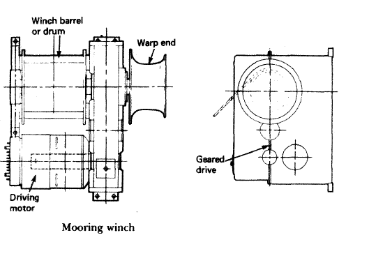
  • Mooring winch is a mechanical device used for securing a ship to the berth. An equipment with various barrels used for pulling ropes or cables, mooring winches play an important role in berthing the ship ashore.
  • The barrels, also known as winch drums, are used for hauling in or letting out the wires or ropes, which will help in fastening the ship to the berth.
  • Mooring winches assembly comes in various arrangements with different number of barrels, depending on the requirement of the ship.
  • The main parts of mooring winch includes a winch barrel or a drum, a warp end and a driving motor. Modern mooring winches comprises of elaborate designs with various gear assemblies, which can be electric, pneumatic or hydraulic driven.

Windlass Winch:-

Windlass Winch
Windlass Winch
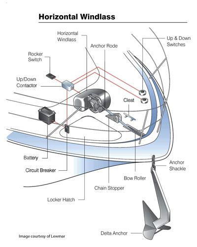
  • A windlass is a machine used on ships that is used to let-out and heave-up equipment such as a ship’s anchor or a fishing trawl. On some ships, it may be located in a specific room called the windlass room.
  • An anchor windlass is a machine that restrains and manipulates the anchor chain on a boat, allowing the anchor to be raised and lowered by means of chain cable. A notched wheel engages the links of the chain or the rope.
  • A trawl windlass is a similar machine that restrains or manipulates the trawl on a commercial fishing vessel. The trawl is a sort of big fishing net that is wound on the windlass.
    The fishermen either let-out the trawl or heave-up the trawl during fishing operations. A brake is provided for additional control. The windlass is usually powered by an electric or hydraulic motor operating via a gear train.
  • Technically speaking, the term “windlass” refers only to horizontal winches. Vertical designs are correctly called capstans. Horizontal windlasses make use of an integral gearbox and motor assembly, all typically located above-deck, with a horizontal shaft through the unit and wheels for chain and/or rope on either side.
    Vertical capstans use a vertical shaft, with the motor and gearbox situated below the winch unit (usually below decks).

Q) List the routine maintenances carried out on board.

Ans:- Efficient planning and adequate usage of equipments is the key to productive maintenance.

Types of Maintenance Procedures:-

  1. Preventive or Scheduled Maintenance System: – It is famously known as the PMS or Planned Maintenance System. In this type of system the maintenance is carried out as per the running hours like 4000 hrs, 8000 hrs etc., or by the calendar intervals like 6 monthly, yearly etc. of the machinery. The maintenance is carried out irrespective of the condition of the machinery. The parts have to be replaced if it is written in the schedule, even if they can be still used.
  2. Corrective or Breakdown Maintenance: – In this system the maintenance is carried out when the machinery breaks down. This is the reason it is known as the breakdown maintenance. This is not a suitable and good method as situations may occur wherein the machinery is required in emergency. The only advantage of this system is that the working of machinery parts is used to its full life or until it breaks. This system might get costly as during breakdown several other parts may also get damaged.
  3. Condition Maintenance system: – In this system the machinery parts are checked regularly. With the help of sensors etc. the condition of the machinery is accessed regularly and the maintenance is done accordingly. This system requires experience and knowledge as wrong interpretation may damage the machinery and lead to costly repairs which may not be acceptable by the company.