Posted on Leave a comment

Responsibilities of Chief officer with respect to Documents on board

Responsibilities of Chief Officer with respect to signing of Mates receipts:-

  • Remarks to be made as to the order and condition of the consignment. This document is usually prepared by the terminal or shipper’s representative at the terminal.
  • In addition to the condition of the cargo it will usually the description of the goods, the shipper’s quantity and/or weight and usually the packaging.
  • This receipt is signed, after loading, by the Chief Officer as an official receipt for the goods onboard. The original mate’s receipt is then usually presented to the carrier and exchanged for signed original bills of lading issued by the carrier using the quantities shown on the mate’s receipt. These original bills of lading then act as the receipt for goods.

Responsibilities of Chief Officer with respect to issuance of letter of protest to shippers and cargo receivers:-

  • A Letter of protest, simply known as Protest, is a written communication, intended to record dis-satisfaction on the part of one party concerning any operational matter over which the recipient or other party has control, and holding the other party responsible for the consequences of the matter being complained of.
  • Most commonly a protest is in connection with cargo, although they may be written about almost any matter where there is a contractual arrangement. e.g. Use of berth or use of equipment.
  • A Letter of Protest helps substantiate a claim by owners or vice-versa, and may prove useful, if properly filed, when a dispute is being resolved long after the related event.
  • A Letter of Protest is thus different from a Note of Protest or lodged with a consul or notary public.
Posted on Leave a comment

Inspection of Cargo Gears

Requirements & Procedure to be followed for thorough examination of cargo gears and load testing of lifting appliances as prescribed in Dock Workers (Safety, health and welfare) Act 1990 and rules / regulations framed there under:

Test and periodical Examinations of lifting appliances:-

  1. Before being taken into use for the first time or after It has undergone any alternations or repairs liable to affect its strength or stability and also once at least in every five years, all lifting appliances including all parts and gears thereof, whether fixed or moveable, shall be tested and examined by a competent person in the manner set out in the regulation.
  2. All lifting appliances shall be thoroughly examined by a competent person once at least In every 12 months. Where the competent person making this examination forms the opinion that the lifting appliance cannot continue to
  3. Function safely, he shall forthwith give notice in writing of his opinion to the owner of the lifting appliance or in case of lifting appliance carried on board a ship not registered in India, to the Master or officer-in-charge of the ship.
  4. Thorough examination for the purpose of this regulation shall mean a visual examination, supplemented if necessary by other means such as hammer test, carried out as carefully as the conditions permit, in order to arrive at a reliable conclusion as to the safety of the parts examined; and if necessary for this purpose, parts of the lifting appliance and gear, shall be dismantled.

Maintenance and Inspection of the Cargo Gears:-

  • The maintenances of the cargo handling gear will be included in a planned maintenances system as required by the ISM Code.
  • There are two basic requirements when maintaining cargo gear:
    • To keep the equipment in good safe working order and
    • To keep the supporting documentation in good order.
  • The maintenance of the Derricks and associated gear aboard a ship which has been well maintained can be summarized as follows:
    • Daily, when Derricks are being used to work Cargo: Inspect runner wirers for wear or damage. Check the rig for damage or for fastening.
    • Before Arrival in port: Inspect Derrick in the associated gear to ensure that they comply in every respect with the requirements on the flag state and of the port to be visited.

Test & Periodical Examination of Lifting Appliances:-

  • Before being taken into use for the first time or after it has undergone any alterations or repairs liable to affect its strength or stability and also once in every 5 years, all lifting appliances including, all parts & gears thereof, whether fixed or moving, shall be examined by a competent person in the manner set out in the regulation.
  • All lifting appliances shall be thoroughly examined by a competent person once atleast every 12 months, termed as periodic (visual) survey. The survey must be done by a competent person, often the chief officer, though some authorities require the survey to be carried out by an independent surveyor.
  • When the ship’s cargo gear is in frequent use all checks required by the survey should be done by the ship’s staff move often then once a year, even when regulation require an annual survey.
  • The rigging arrangements must confirm to the rigging plan.

Before Examination:-

  • All assembled items such as goose necks and blocks should be dismantled, so that the component parts can be readily inspected.
  • Shackles, links, rings, hooks, triangle plates, chains, etc. must be sufficiently free of paints & grease scales to enable proper inspection to be made.

Items to be examined:-

  • Deformation, wear, scoring, corrosion, scars, dents or other defects is to the structure & fittings.
  • In structural members, the maximum permitted wear down or corrosion is 10 % of the diameter. If the metal appears to be wasted or worn the thickness should be checked using calipers against the original specification.
  • In loose gear the maximum permitted weardown or corrosion is 5% on any diameter and 2% of any diameter of a pin in a hole.
  • Wire ropes should be inspected over their entire length with particular attention to end fittings, ferrules & splices.
  • Wire ropes must be renewed if the number of broken, warn or corroded wires in any length of 1 diameters exceeds 5 %.
  • ➢    Fibre ropes should be examined over their entire length for external chafe and cutting, for internal wear between strands for mildew, rot chemical attack or other contamination.
  • The Derrick boom, particularly at the point where it rests in its crutch or housing shall be thoroughly checked.
  • A Derrick shall be tested with its boom at the minimum angle to the horizontal (generally 15O) or at such angles as may be indicated in the test certificate. The test load suspended and the boom shall be swing as far as practicable in both directions (P & S).
  • Cranes shall be tested similarly with movable weights, at maximum, minimum & intermediate radius points.

Heat Treatment of Loose Gears:-

  • All chains other than bridle chains attached to the Derricks on mast and all rings, hooks, shackles & swivels used in hosting or lowering shall be subjected to heat treatment at the following intervals:
    • 12.5 mm and smaller chains, rings, hooks, shackle & swivels in general use, once atleast every six months.
    • All other chains, rings, hooks, shackles and swivels in general use once every 12 months.
  • All chains & loose gears made from high tensile steel or alloy steel be plainly marked with an approved mark, shall not be subjected to any form of heat treatment except where necessary for the purpose of repair & under direction of a competent person.

Regular Maintenance of Cranes:-

  • The filters of the hydraulic system must be regularly cleaned or renewed and the hydraulic oil must be charged as required by the manufacturers.
  • The oil in the gear boxes must be kept topped up to the correct level and must be changed at required intervals.
  • Suitable grease must be applied to all moving ports of the system such as bearing of winches, sheaves, pivot points, etc.
  • Wire ropes must be inspected for any signs of worm or corrosion and must be condemned if more than 5 % of the wires in any length of 10 diameters are damaged.
  • The brakes for the hoisting winch & for the stowings & luffing which must be regularly inspected.
  • Limit switches and the over ride keys for the over-hoisting or for the luffing & slewing travelling beyond permitted limits must be tested frequently and certainly before each port visit to ensure correct operation & position at the limit switches.
  • The planned maintenance for a hosting and luffing wires should be when required on working hours or two years, whichever comes first.

Justify the statement the planned maintenance of ship proves cost effective in the long run:

The main aim of any maintenance plan on ship is to get the maintenance and repair work done in the least possible time with minimum costs.

A maintenance plan is therefore followed by every shipping company to ensure that the ship’s machinery maintains a particular standard of operation and safety.

Maintenance plan is an imperative element of ship’s routine operations and also forms an integral component of ship’s maintenance mechanism.

While making a maintenance plan, several aspects are taken into consideration, starting from the International safety management code (ISM) to the guidelines put forth by the machine manufacturers.

Objectives of a maintenance plan:-

  • As mentioned before, the main objective of a maintenance plan is to make sure that the work is done in the least possible time with utmost efficiency and at optimum cost.
  • Various points mentioned in the ISM code are taken into consideration, along with company’s procedures and manufacturer’s guidelines.
  • Other aspects include type of the ship, condition of the ship, age of the ship etc.
Posted on Leave a comment

Duties of Dock Safety Inspector on Ship

Duties of Dock Safety Inspector are as follows:-

  • Perform daily dock check list.
  • Welcome new slip holders and/or transients in a manner which expresses a kind, courteous and professional character.
  • Maintain and clean rest rooms, docks, walkways, ramp ways, grounds, equipment and other areas designated by the Dock Master.
  • Maintain an inventory of supplies as needed.
  • Ensure docks, equipment and facilities are operational at all times.
  • Assist and support special events/activities taking place at the marina.
  • Inspect docked vessels such as dock lines, electrical cords, Comcast cable connections and fenders to ensure safety.
  • Perform daily trash removal (morning and evening trash) and dispose of as directed.
  • Maintain the daily operation of the sewage pumping system.
  • Perform electrical meter readings at slip pedestals and report readings.
  • Insure that no slip holder installs, secures or attaches items to the pier, bulkhead, light poles, pedestals or any other areas which are the property of the marina without written consent to do so
  • Perform marina safety inspections including, but not limited to the following:
    • Wood slat inspections
    • Concrete inspections
    • Light pole inspections
  • Vessel inspections consisting of vessel stability, frayed lines, electrical cords and Comcast connections.
  • Life ring inspection.
  • Report any notice of “sheen” in the water immediately.
  • Immediately notify the appropriate party if fuel is observed either visually or by smell.
  • Other duties as assigned.
Posted on Leave a comment

Tallying of Cargo

Tallying of Cargo as per stowage plan on completion of loading:

Once the cargo has been loaded on board the vessel will expected to make an accurate tally of the total number of units loaded onboard and their destination ports. Although in many ports this will be provided to the vessel by the tally clerks, it is common practice that many ports are entirely dependent on the tally provided by the ships staff. So in this respect it is important that procedure is in place to ensure that ship side tally is well maintained and is reported and confirmed with the operators and stevedores to prevent any short landing / Overlanding Discrepancies.

Tallying of Cargo as per stowage plan on completion of Discharging:

Prior vessel arrives at the first discharge port it is important that a shortlanding/ overlanding checklist is Completed and sent to the respective discharge ports stevedores through the agents. During the loading stage the duty officers and crew where totally involved in the stowage/segregation process so once the vessel leaves the last loading port it is important that the chief officer carries with him all the crew and officers for cargo rounds and familiarize the cargo plan and the precautionary areas where due to location of cargo in hidden spaces / areas they might be overlooked. These areas should be promptly marked and identified on the cargo plan.

Posted on Leave a comment

Definitions as per ILO Conventions applicable to Ships

Definitions as per ILO Conventions occupational Safety and Health Convention 1990, applicable to ships:

Authorised person means a person authorised by the employer, the master of the ship or a responsible person to undertake a specific task or tasks and possessing necessary technical knowledge and experience for undertaking the task or tasks.


Responsible person means a person appointed by the employer, the master of the ship, the owner of the gear or port authorities, as the case may be, to be responsible for the performance of a specific duty or duties and who has sufficient knowledge and experience and the requisite authority for the proper performance of the duty or duties.


Loose Gear” means hook, shackle, swivel, chain, sling, lifting beam, container speader, tray and any other such gear, by means of which the load can be attached to a lifting appliance and includes lifting device.


Competent Person means.-

(i) a person belonging to a testing establishment in India who is approved by the Chief Inspector for the purpose of testing, examination or annealing and certification of lifting appliances, loose gears or wire ropes;

(ii) any other person who is recognised under the relevant regulations in force in other countries as competent for issuing certificates for any of the purposes mentioned in sub-clause (1) for the implementation of the Protection against Accidents (Dockers) Convention (Revised), 1932 (No. 32) and the Convention concerning Occupational Safety and Health in Dock Work (No. 152), 1979, adopted by International Labour Conference.


Powers of Inspector” Powers of Inspectors.-(a) An Inspector may at any port for which he is appointed-

(i) enter, with such assistance, (if any), as he thinks fit, any ship, dock, warehouse or other premises, where any dock work, is being carried on, or where he has reason to believe that any dock work is being carried on;

(ii) make examination of the ship, dock, lifting appliance, loose gear, lifting device, staging, transport equipment, warehouse or other premises, used or to be used, for any dock work;

(iii) Require the production of any testing muster roll or other document relating to the employment of dock workers and examine such document;

(iv) Take on the spot or otherwise such evidence of any person which he may deem necessary:

Provided that no person shall be compelled under sub-regulation 3 (a) (iv) to answer any question or, give any evidence tending to incriminate himself;

(v) take copies of registers, records or other documents or portions thereof as he may consider relevant in respect of any offence which he has reason to believe has been committed or for the purpose of any inquiry;

(vi) take photograph, sketch, sample, weight measure or record as he may consider necessary for the purpose of any examination or inquiry;

(vii) hold an inquiry into the cause of any accident or dangerous occurrence which he has reason to believe was the result of the collapse or failure of any lifting appliance loose gear, transport equipment, staging non-compliance with any of the provisions of the Act or the regulations;

(viii) issue show-cause notice relating to the safety, health and welfare provisions arising under the Act or the regulations;

(ix) prosecute, conduct or defend before any court any complaint or other proceedings, arising under the Act or the regulations;

(x) direct the port authority, dock labour board and other employers of dock workers for getting the dock workers medically examined if considered necessary.

(b) A person having general management and control of the premises or the owner, master, officer-in-charge or agents of the ship, as the case may be, shall provide such means as may be required by the Inspector for entry, inspection, examination, inquiry, otherwise for the exercise of his powers under Act and the regulations in relation to that ship or premises which shall also include the provision of launch or other means of transport.


The term Lifting Appliances  covers all stationary or mobile cargo-handling appliances used on board ship for suspending, raising or lowering loads or moving them from one position to another while suspended or supported.


Responsible person means a person authorized to permit entry into an enclosed space and having sufficient knowledge of the procedures to be established and complied with on board, in order to ensure that the space is safe for entry.
Posted on Leave a comment

Test & Certification Procedure for Approved Loadicator

Testing requirements for the Loadicator:

Testing by ship staff: The Loadicator is required to be tested periodically (interval to be as per SMS of the vessel) by ship staff for its accuracy. The test procedure includes choosing a text condition from the approved test conditions, entering the exact same data in the loadicator and comparing the results with the approved test conditions. The important point to note is that the data need to be manually entered and not opened from a pre-saved file as it is not acceptable to classification society as well as OCIMF to simply retrieve a stored test condition and comparing it with approved test condition.

Annual testing of Loadicator in presence of Class: During annual class surveys, loadicator need to be tested for its accuracy in presence of a class surveyor. The procedure of testing is same as the quarterly testing but in here the class surveyor would ask for the print out of the test condition and he would stamp it and give it to the ship for ship’s records.

Procedure for Certification:- The approved test conditions shall be tested on the loading computer system in presence of a surveyor from the Society, before the loading computer certificate is issued.

During the test, the loading conditions calculated on the installed loading computer system shall be verified to be identical to the approved test conditions. If numerical output from the loading computer system is at significant variance with the approved test conditions, a certificate cannot be issued.

During the tests, at least one of the test conditions shall be built up from scratch, to ensure that the loading methods function properly.

As an alternative to 203 can the following procedure be followed:

Retrieve the test load case and start a calculation run; compare stability results with those in the documentation.

Change several items of deadweight (tank weights and the cargo weight) sufficiently to change the draught or displacement by at least 10%. The results shall be reviewed to ensure that they differ in a logical way from those of the approved test condition.

Revise the above modified load condition to restore the initial test condition and compare the results. The relevant input and output data of the approved test condition shall been replicated.

During the test relevant warnings should be checked, which should include max draught, strength limits and stability limits.

Where the hardware is not type approved, the test shall be carried out on both the first and the second nominated computers prior to issuing of the loading computer certificate.

After completion of satisfactory tests, the loading computer certificate shall be issued.

The loading computer certificate and the approved test conditions shall be kept onboard together with the user’s manual.

The certification shall be carried out onboard.

If the final loading manual or the final stability booklet has not been approved before delivery, testing onboard may take place after these documents have been approved.


SOLAS 1974 / Loadline 1966 & Class requirements for approved Loadicator on Board Cargo Ships:

The requirement of loading instrument for bulk carriers is governed by SOLAS chapter XII, regulation 11. Even though there is no statutory requirement for loading computer onboard other ships, classification societies require all tankers of more than 100 meters to have type approved loading instrument. Even otherwise so, Loadicator has rather been a necessity onboard ships. And once we have something onboard, it is duty of ship staff to ensure that it complies with its testing and record keeping procedures.

There are two parts of the question. First relates to the documents and certificates a ship is required to have onboard with respect to loadicators and second the testing requirement of the loadicator.

Documents required for Loadicator:

There are three main documents ship should have for it to be actually complying with Loadicator requirements. These are:-

  • Class certificate for loadicator: This certificate is issued by the class and gives the details of the loadicator software as well as the hardware on which it is installed, including the details of the Make, model and serial number of the computer. Master and chief officer must ensure that the approved loading computer’s details matches with the details in this certificate. The certificate may even sometimes have the printer’s detail that is connected with the approved loadicator. If you do not find this certificate onboard, you should check in the class survey status report if the loading computer is included in the list. If yes, the certificate can be asked from the class through your office. If No, then shipping office need to consult ship’s classification society for approval of loading computer.
  • Class approved Loadicator Manual: This is the user manual of the loadicator which is from the maker of the loadicator software. A class approved copy of the user manual should be onboard. If there was ever a class change associated with the ship, it is important to ensure that approval stamp of the current classification society is endorsed on the manual.
  • Class approved loadicator test conditions: To be very clear, these are not the conditions in the stability booklet of the ship. The stability conditions in the stability booklet are made by the yard and these are not the print outs from the loadicator software. These are also not the test conditions stamped by the class during annual class surveys. These are usually in the form of a booklet specifically titled “test conditions for loadicator” with class stamp. These are usually provided during yard delivery of the vessel or after the loadicator is installed for the first time and approved by the class.
  • Once we have these three documents / certificates, you are OK with the certification part.
Posted on Leave a comment

Inspection & Maintenances of Wire Ropes

Procedure for Inspection Of Wire Rope:-

A visual and physical examination should take place at regular intervals.  Under normal conditions of use, wire rope can be inspected every 3 months.  If a broken wire is discovered, then it should be inspected more often.  A thorough inspection is given below.

Externally

  1. Inspect termination of rope at the drum and other points.
  2. Inspect for broken wires.
  3. Inspect for corrosion.
  4. Inspect for deformation.
  5. Inspect for surface wear.
  6. Inspect for defective coiling.
  7. Inspect for deterioration due to snatch loading.
  8. Inspect lengths that run through blocks, particularly those which lie on the sheaves when the appliance is in the loaded condition.

Internally

Open the lay.

  1. Check internal lubrication.
  2. Degree of corrosion.
  3. Indentation caused by pressure of wear.
  4. Presence of broken wires.

An accurate log should be kept of inspection dates, rope condition, end for ending, replacement, etc.

Broken Wires: – Broken wires are usually a result of fatigue and wear.

Discard if:

Marine Order (part 32) “The total number of broken wires visible in a length of S.W.R. equal to 10 times it’s diameter should not exceed 5% of the total number of wires constituting the rope”.

Strand Distortion

Strand distortion is generally a result of damage caused by kinking, crushing, bad nips or other violent treatment.  Commonly found in berthing hawsers, and ropes which have to be worked in adverse conditions.

Abrasion

Occurs both internally and externally. 

Caused by:-

  1. Friction over sheaves, leads, sharp or rough objects
  2. Dirt, dust, grit lodging within strand wires.

Indicated by:-

  1. Deposits of fine brown powder between strands
  2. Flattening of internal surfaces of individual wire.

Corrosion

Generally caused by lack of lubrication.  When wire rope is under tension, the fibre heart and cores are also compressed, releasing oil to overcome friction.

Maintenance of wire ropes:-

Uncoiling New Cordage

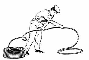
Below 48 mm the rope can be taken direct from the inside of the coil.  This will maintain its protective wrapping.  With right handed rope the coil should be stood on the end which will allow the rope to be taken off left handed from the inside.

Maintenance of Wire Ropes - Uncoiling New Cordage
Maintenance of Wire Ropes – Uncoiling New Cordage

Uncoiling the rope in the wrong direction will insert twist and increase the danger of kinking.

Coiling

Always coil ropes in the direction of Lay,

ie., Left hand (L.H.) lay anti-clockwise

                                               Right hand (R.H.) lay clockwise 

Maintenance of Wire Ropes - Coiling
Maintenance of Wire Ropes – Coiling


Two methods of finishing coils are shown in the above figure. 

Maintenance of Wire Ropes - Two Methods of finishing coils
Maintenance of Wire Ropes – Two Methods of finishing coils


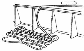
To avoid problems in paying out a rope, it should be flaked down, see Figure.  This avoids it becoming tangled or kinked. 

Maintenance of Wire Ropes - Paying out a rope
Maintenance of Wire Ropes – Paying out a rope

A fancy way to finish a rope is with a Flemish Coil.  It SHOULD ONLY be used for tidiness and never when required to render quickly through a block, see Figure.

Before cutting the desired length of rope, whippings should be applied close to each side of the intended cut.  Failure to observe this precaution can cause excessive unlaying of the rope.

Care and Maintenance

Chemicals: – Natural fibre rope is severely damaged by chemicals. Synthetic ropes are much more resistant.

Heat: – Excessive heat will melt synthetic ropes and make natural ropes dry and brittle.

Storage: – Store ropes in a well-ventilated dry atmosphere away from heat, strong sunlight and corrosive substances.  Natural fibre rope will quickly rot if stowed away wet. Always dry out before storing.  Keep loose coils OFF the deck.

Cleaning of Ropes:

If a rope has been used in mud, sand or grit, it should be cleaned thoroughly before being stored.  To wash rope, hang it up in loose coils or flake it out on the deck and hose with fresh water.

Posted on Leave a comment

Inspection of Vulnerable Areas

Inspection of Vulnerable Areas in the Dry Cargo Holds for Damages:

When a vessel requires repairs to damaged equipment or to the hull it is necessary for the work to be carried out to the satisfaction of the classification society surveyors. In order that the ship maintains its class, approval of the repairs undertaken must be obtained from the surveyors either at the time of the repair or at the earliest opportunity.

Terminal operators should be aware of the damage that their cargo handling equipment can inflict on the ship’s structure. It is important that the protective coatings in cargo holds and water ballast tanks are maintained.

The cargo holds and deck areas should be inspected by the ship’s deck officers upon completion of cargo discharge to identify any signs of physical damage, corrosion or coating damage to the ship’s structure. Where hull damage is identified, which may affect the integrity of the hull structure and the seaworthiness of the ship, it should be reported accordingly to the classification society.

Cargo watch on deck should monitor stevedore grab handling and damage. Crane drivers should be advised to take care not to damage ship structure cargo watch on deck should monitor ballast operations cargo watch on deck when the ship is carrying water-sensitive cargoes should identify the potential for water to leak from a crack or damage in the hold plating following grab damage consider gravitating ballast, to reduce pressure on ballast tank structures a rigorous sounding regime should be maintained in port.

The internal hold structure and protective coatings in the cargo hold and the adjacent double bottom are vulnerable to damage when the cargo is discharged using grabs. The weight of empty grabs can be 35 tonnes. Other types of equipment employed to free and clear cargo, including hydraulic hammers fitted to extending arms of tractors and bulldozers can inflict further damage to the ship’s structure, especially in way of the side shell and the associated frames and end brackets. Chipping (sharp indentations) and the local buckling or detachment of side frames at their lower connection could lead to cracking of the side shell plating which would allow the ingress of water in to the cargo space.

The protective coatings which may be required to be applied in the cargo hold are also subject to deterioration caused by the corrosive nature of the cargo, high temperature cargoes, cargo settlement during the voyage and the abrasive action of the cargo. Where no protective coatings have been applied or the applied protective coatings have broken down, the rate of corrosion in that area will greatly increase, especially when carrying corrosive cargoes, such as coal.

Corrosion will weaken the ship’s structure and may, eventually, seriously affect the ship’s structural integrity. The severity of the corrosion attained by a structural member may not be easily detected without close- up inspection or until the corrosion causes serious structural problems such as the collapse or detachment of hold frames resulting in cracks propagating in the side shell.

Impact damage to the inner bottom plating or the hopper sloping plating will result in the breakdown of coatings in the adjacent water ballast tanks, thereby intensifying the rate of structural deterioration.

Solas 74 as amended Chapter XII: Additional safety measures for bulk carriers Regulation 5: (This regulation applies to bulk carriers constructed on or after 1 July 1999)

Bulk carriers of 150 m in length and upwards of single side skin construction, designed to carry solid bulk cargoes having a density of 1,000 kg/m3 and above, shall have sufficient strength to withstand flooding of any one cargo hold in all loading and ballast conditions, taking also into account dynamic effects resulting from the presence of water in the hold, and taking into account the recommendations adopted by the Organization.

Regulation 6: Structural and other requirements for bulk carriers (This regulation applies to bulk carriers constructed before 1 July 1999):-

  1. Bulk carriers of 150 m in length and upwards of single side skin construction, carrying solid bulk cargoes having a density of 1,780 kg/m3 and above, shall comply with the requirements of this regulation in accordance with the implementation schedule specified in regulation 3.
  2. The transverse watertight bulkhead between the two foremost cargo holds and the double bottom of the foremost cargo hold shall have sufficient strength to withstand flooding of the foremost cargo hold, taking also into account dynamic effects resulting from the presence of water in the hold, in compliance with the bulk carrier bulkhead and double bottom strength standards. For the purpose of this regulation, the bulk carrier bulkhead and double bottom strength standards shall be treated as mandatory.
  3. In considering the need for, and the extent of, strengthening of the transverse watertight bulkhead or double bottom to meet the requirements of paragraph 2, the following restrictions may be taken into account:
    • Restrictions on the distribution of the total cargo weight between the cargo holds; and
    • Restrictions on the maximum deadweight.
  4. For bulk carriers using either of, or both, the restrictions given in paragraphs 3.1 and 3.2 above for the purpose of fulfilling the requirements of paragraph 2, these restrictions shall be complied with whenever solid bulk cargoes having a density of 1,780 kg/m3 and above are carried.

Vulnerable Areas in Ship’s Cargo holds where infestation may take place:

  • Tank top ceiling: If, as often happens, cracks appear between the ceiling boards, food material may be forced down into the underlying space and serve as a focus of infestation for an indefinite period. Insects bred in this space can readily move out to attack food cargoes and establish their progeny in them.
  • ‘Tween-deck centre lines, wooden feeders and bins are often left in place for several voyages and because of their construction are a frequent source of infestation. After unloading a grain cargo, burlap and battens covering the narrow spaces between the planks should be removed and discarded before the holds are cleaned or washed down. These coverings should be replaced by new material in preparation for the next cargo.
  • Transverse beams and longitudinal deck girders which support the decks and hatch openings may have an L-shaped angle-bar construction. Such girders provide ledges where grain may lodge when bulk cargoes are unloaded. The ledges are often in inaccessible places overlooked during cleaning operations.
  • Insulated bulkheads near engine-rooms: When the hold side of an engine-room bulkhead is insulated with a wooden sheathing, the airspace and the cracks between the boards often become filled with grain and other material. Sometimes the airspace is filled with insulating material which may become heavily infested and serves as a place for insect breeding. Temporary wooden bulkheads also provide an ideal place for insect breeding, especially under moist conditions, such as when green lumber is used.
  • Cargo battens: The crevices at the sparring cleats are ideal places for material to lodge and for insects to hide.
  • Bilges: Insects in accumulations of food material are often found in these spaces.
  • Electrical conduit casings: Sometimes the sheet-metal covering is damaged by general cargo and when bulk grain is loaded later, the casings may become completely filled. This residual grain has often been found to be heavily infested. Casings that are damaged should be repaired immediately or, where possible, they should be replaced with steel strapping, which can be cleaned more easily.
  • Other places where material accumulates and where insects breed and hide include:
    • The area underneath burlap, which is used to cover limber boards and sometimes to cover tank top ceilings.
    • Boxing around pipes, especially if it is broken.
    • Corners, where old cereal material is often found.
    • Crevices at plate landings, frames and chocks.
    • Wooden coverings of manholes or wells leading to double-bottom tanks or other places.
    • Cracks in the wooden ceiling protecting the propeller shaft tunnel.
    • Beneath rusty scale and old paint on the inside of hull plates.
    • Shifting boards.
    • Dunnage material, empty bags and used separation cloths.
    • Inside lockers.
Posted on Leave a comment

Damage to Cargo Spaces on Ships

Common damage/ defects that may occur on watertight transverse bulkheads situated at the ends of dry cargo holds of a bulk carrier.    

The following are examples of the more common damage/defects that may occur:

  1. Fractures at the boundaries of corrugations and bulkhead stools, particularly in way of shelf plates, shedder plates, deck, inner bottom, etc..
  2. Buckling of the plating/corrugations, leading to the failure and collapse of the bulkhead under water pressure in an emergency situation. .
  3. Excessive wastage/corrosion, in particular at the mid-height and bottom of bulkheads, which may look in deceptively good condition. This is created by the corrosive effect of cargo and environment, in particular when the structure is not coated. In this respect special attention should be given to the following areas:
    • Bulkhead plating adjacent to the shell plating;
    • Bulkhead trunks which form part of the venting, filling and discharging arrangements between the topside tanks and the hopper tanks;
    • Bulkhead plating and weld connections to the lower/upper stool shelf plates;
    • Weld connections of stool plating to the lower/upper stool shelf plates and inner bottom;
    • In way of weld connections to topside tanks and hopper tanks;
    • Any areas where coatings have broken down and there is evidence of corrosion or wastage. It is recommended that random thickness determination be taken to establish the level of diminution; and
    • Other structures, e.g., diaphragms inside the stools, particularly at their upper and lower weld connections.

Actions you would take as a Chief Officer to avoid the detrimental effects on bulk carriers due to corrosion, fatigue and improper cargo handling:

Fracturing of the Structural members of a transverse bulkhead of a Bulk carrier are:-

  1. Side Shell Plating
  2. Connection of Bulkhead plating to side shell.
  3. Connection of side shell frame & end brackets to the shell plating and hopper side tank plating by close-up inspection.
  4. Connection of side shell frame & end brackets to the shell plating and topside tank plating.

Actions to control structural stresses and fatigue:-

  1. Routing Planned Maintenance & Inspection of Structural members of cargo holds & hatch covers.
  2. Identification of susceptible areas prone to Fatigue & Stresses.
  3. Ensure accessibility of the area to be surveyed with due regards to the area under inspection shall be clean and will lit.
  4. Careful planning of the surveys to be undergone with all personnel involved.
  5. Where a fracture which not been caused by contact damage is found in the main hull structure on one side of a ship, corresponding structure on the opposite side should be examined to see if a similar fatigue has occurred. Fractures of this nature are of concern, especially where corrosion is associated with failure & may have been contributing factor.

Structural Surveys include:-

  1. Routine Inspections.
  2. Planning Surveys
  3. Surveys of known defects.
  4. Classification surveys.
  5. Annual surveys
  6. Intermediate Surveys
  7. Special surveys
  8. Condition Surveys
  9. CAP Surveys
  10. Life extension surveys, etc.

Fatigue cracking of steel structures:-

  • Fatigue cracking occurs at points such as hatch covers where stresses are locally high.
  • Such cracking is the result of cumulative damage caused by cyclic loading of structure & invariable starts at welded joints.
  • The fatigue life is the time required in service for the structure to experience enough stress cycles for a crack to occur. A bulker is so designed that with proper maintenance cracking should not occur until a fatigue life span of 20 years.
  • Fatigue life span once used up cannot be regained except by complete replacement of welded joints.
  • Therefore, it is very essential that the welded joints of an overstressed structure are replaced, before proceeding with life exterior surveys/ programmes.
  • Fatigue cracking have been most frequently observed in the bracket toes at the connection of the main frames to the hopper and topside tanks and in the boundaries of the vertically corrugated transverse bulkheads with upper stools, lower stools and topside tanks.

Corrosion / Structural Deterioration:-

  • The major barrier preventing structural deterioration on ships, especially in very corrosive environment of Water Ballast Tanks and to a slightly lesser extent cargo holds is the tank/ hold coating. Since the establishment of ESP water ballast tanks and CH of all new ships must be fully coated. Such coatings should be hard coating & preferably light in colour.
  • To maintain a good and efficient standard of coating is an important part of structural condition management. If coatings are kept in good condition the structure will be effectively protected and the original scantlings will be available to resists “service loads” & “stresses”.
  • Sea staff therefore should meaningfully report the condition of tank/ hold coatings during routines inspections and same to be documented in the company PMS system.
  • The most effective method of protecting a structure of a bulk carrier is to maintain coatings and carry out repairs of coating breakdown in good time.
  • Installation of Anodes, subject to the tank being regularly ballasted is an effective back-up that will prevent accelerated corrosion in the way of local coating breakdown.
  • The most effective time to carry out coating repairs in the tanks i.e. freshwater washing, surface preparation and coating application, can be done during a routine repair period of reasonable duration.

Damage to ship structure by improper cargo handling:-

  • Ships can be and are frequently damaged during discharging discharging over this especially if the operation is carried out by grabs or payloaders making heavy contact with the ship’s structure.
  • Local overloading, when bulk corners are loaded in ways not for seen by their classification society or shown in their loading manual, resulting in cracking of deck plating at the hatch covers & backing of plating between the hatchways.
  • A faulty distribution of weight can occur when:-
    • A ship jump loads to her tropical marks and corner less than full bunkers. In that situation some or all of the strengthened holds are subjected to greater tonnage of cargo than they were designed to carry.
    • Particular holds are loaded with greater tonnage then the tonnage for which the hold was designed.
    • The vessel is block loaded – i.e., where two or more adjoining holds are heavily loaded with adjacent holds empty. Although it is imperative that the longitudinal stresses are negligible but still the vessel suffers structural damage of the cross deck structures which separates adjacent cargo hatchways at the upper deck level.
  • Failure to Trim cargo reasonably:-
    • Cargoes with a low angle of repose are particularly liable to dry surface movement aboard ship.
    • To overcome this problem the code states that such cargoes should be trimmed as reasonably leveled & spaces completely filled without causing any excessive stresses on adjoining structure.

Importance of assessing defects and damage to cargo spaces:-

  1. It is important that the protective coatings in cargo holds and water ballast tanks are maintained. Therefore, it is imperative that the cargo holds and deck areas should be inspected by ship’s deck officers upon completion of cargo operations to identify any signs of Physical Damage, corrosion or coating damage to the ship’s structure.
  2. Where hull damage is identified, which may affect the integrity of the hull structure and sea-worthiness of the ship, it should be reported accordingly to the classification society.
  3. The internal hold structure and protective coatings in the cargo hold and adjacent double bottom spaces are vulnerable to damage when the cargo is discharged by using grabs. Grabs are made from toughened steel material and when carelessly used can cause considerable damage to the ship’s structure.
  4. Chipping (sharp indentations) and the local buckling or detachment of side frames and end brackets at lower connections could lead to cracking of the side shell plating which would allow the ingress of water into the cargo spaces.
  5. The protective coating which may be required to be applied in the cargo hold are also subject to deterioration caused by the corrosive nature of the cargo, high temperature cargoes, cargo settlement during the voyage and abrasive action of the cargo.
  6. Where no protective coating has been applied or the applied protective coatings have broken down, the rate of corrosion in that area will greatly increase, especially when carrying corrosive cargoes such as coal.
  7. Corrosion will weaken the ship’s structure and may eventually seriously affect the ship’s structural integrity. The severity of the corrosion caused by a structural member may not be easily detected, without close-up inspection or until the corrosion causes serious structural problems such as the collapse or detachment of hold frames, resulting in cracks propagating in the side shell.

It is therefore extremely important for a close-up inspection of the cargo spaces, after discharge operations when such corrosive and high temperature cargoes are being carried.

  • When the main grab discharge is ended, front end loaders (Pay Loaders) are usually lowered into the hold to gather the cargo from the ends and wings and pile it in the square of the hatch, to facilitate easy discharge by the grab.

Also, trimmers men are employed to shovel up the last of cargo from the position which front end Payloader, cannot reach, i.e. all the inaccessible places, elsewhere by the Payloader, in order to assist in discharge of final remaining cargo.

  • Standards of trimming vary considerably and ship’s officers are therefore encouraged to inspect the holds, thoroughly, whilst the trimmers are working in the hold, in order to remove as much residual cargo as possible. Thereby, utilizing the maximum efficiency and preparing hold for hold cleaning preparations.
  • The final inspection, after each cargo operation should include that no bilge gratings or manhole cover plates are missing that the securing bolts have not been damaged, that all the sounding pipes, airpipes and ballast lines and their pipeguards are intact, that no new indents can be seen in the plating of the tanktop, lower or upper hopper sides, or athwart ship bulkheads, that the side frames are regular and undamaged with brackets undamaged and that the hold ladders platforms, rails are complete and undamaged.
  • Any damage to the tank top plating, hopper sides, shell plating and framing, hatch coamings, hatch covers, bulkheads, stools and upper deck plating, air and sounding pipes, which could affect the sea-worthiness of the vessel, should be directly reported to the classification society.
Posted on

Bulkheads

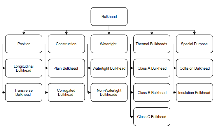
Types of Bulkheads:

Bulkheads:- Vertical partitions on a ship are called bulkheads.

Types of Bulkhead as per Orientation:

  • Longitudinal: Placed in longitudinal direction on a ship.
  • Transverse: placed in Transverse direction on a ship.

Types of Bulkheads as per construction:

  1. Watertight bulkheads: These bulkheads are water tight and prevent flooding. Numbers of Watertight bulkheads: 1- Collision bulkhead, 1- aft peak bulkhead, 1- Bulkhead of engine room and 1- bulkhead aft of engine room. Aft peak bulkhead and bulkhead aft of engine room may be combined into the additional bulkheads are to be provided as per rules depending upon the length of the ship & requirements.
  2. Non-watertight bulkheads:
    • Are screens in accommodation and do not contribute to strength or water tightness.
    • Used to subdivide compartment into smaller units of accommodation of stores Non-watertight Bulkheads.
    • Non-watertight bulkheads perform supporting function.
    • Its stiffeners have to be sufficient for the load carried.
    • Corrugated bulkheads may be used.
  3. On-tight or tank bulkheads: Form boundary of oil tanks. Are oil tight in nature & are tested for the same.
Types of Bulkheads
Types of Bulkheads

Factors to be taken in to account during cargo planning stage in order to minimize the damage to watertight transverse bulkheads and tank tops in bulk carriers having combination cargo/ ballast holds.

The common damage/defects that may occur on watertight transverse bulkheads situated at the ends of dry cargo holds of a bulk carrier:-

  • Fractures that may occur in the deck plating at hatches and in connected comings.
  • Causes of cracking in way of no. 1 cargo hold.

The damages caused by cargoes in cargo holds, especially to tanktop plating and side:

  • At loading and unloading ports for coal or iron ore, large grab buckets, high-capacity cargo.
  • Loaders, bulldozers and pneumatic hammers may be employed for cargo-handling operations.
  • Large grab buckets may cause considerable damage to tank top plating when being dropped to grab cargo.
  • Use of bulldozers and pneumatic hammers may also be harmful to cargo hold structures and may result in damage to tank tops, bilge hoppers, hold frames and end brackets.
  • Lumber cargoes may also cause damage to the cargo hold structures of smaller bulkers that are employed in the carriage of light bulk cargoes and lumbers.
  • Cracking on large bulk carriers, Ballast tanks. Ability to interpret given figures for bending moments and shear forces.