Information required prior to loading of a given Chemical Cargo in Bulk:
- The correct chemical name of the cargo should be provided so that the appropriate data sheet in the Tanker Safety Guide (Chemicals) can be consulted.
- Quantity in Weight.
- Required quantity control – Contamination is measured in parts per million (ppm). Thus tanks & pipelines must be practically spotless. Degree of wall-wash required.
- Specific Gravity – This is required in order that an estimation can be made of the probable volume that the weighed quantity will occupy.
- Temperature – This is required for two purposes.
- The loading temperature is used in conjunction with the specific gravity to obtain the probable volume of the particular parcel.
- The temperature at which the cargo is to be carried will indicate if heating will be required on passage. Some chemicals will solidify or polymerize if a certain temperature is not maintained. Polymerization is a chemical reaction in which small molecules combine into larger or very large molecules, which contain thousand of the original molecules. Thus a free flowing liquid can become a viscous liquid or even solid.
- Compatibility – Certain chemicals react with other chemicals and thus may not be stowed in adjacent compartments.
- Tank coating compatibility – The tank coating must be suitable for the proposed cargo.
- Corrosive Properties – This will also indicate the required tank coating and also possible damage to ship fittings.
- Electrostatic generation – Some chemicals can accumulate static, the principles which apply to HC cargoes should be applied to chemical static accumulators.
- Fire & Explosion Data – It has been previously noted that 50 % of the chemicals transported are derived from hydrocarbon oil and thus fire hazards are similar to those which pertain to petroleum products.
- Toxicity – Chemicals which emit highly toxic vapours requires Closed Ventilation and Ullaging System.
- The Health Hazard of the particular parcel.
- Reactivity.
- Action to be taken in the event of particular emergencies – Most of the above information and additional essential information can be found on the chemical data sheets in the safety guide.
Publications which are referred to get info Prior to Loading Chemical Cargo:
- On receipt of the name of the cargo, the certificate of fitness must be checked to verify if the said vessel is allowed to carry that particular cargo as enlisted in the COF.
- Depending on whether the ship is constructed before / after 01-07-1986. The relevant IBC Code / BCH Code must be consulted. Chapter 17 of the IBC code – contains summary of minimum requirements & various information pertaining to the cargo can be obtained.
- Additional information can be obtained from the chemical data sheet pertaining to that cargo – found in the ICS (International Chamber of Shipping) publication. Tanker Safety Guide – Chemical in Volume – I, II, III & IV.
- Also added information can be obtained from USCG system. CHRIS – Chemical Hazard Response Information System, provided for essential decision making during emergencies involving the water transport of the hazardous chemicals.
- The “Procedure & Arrangement” (P & A) manual which is ship specific, gives information such as tank arrangement, pumping & piping arrangements any special requirements to assists any loading can be obtained.
- Annex 2 of the MARPOL 73/78 should be referred to obtain discharge criteria & procedure.
- Paint compatibility guide – to check if the coating in the tank will withstand with particular cargo to load.
Types of Chemical Tankers:
There are 3 basic types of Chemical Tankers, All 3 types are meant to carry chapter 17 cargoes of IBC code.
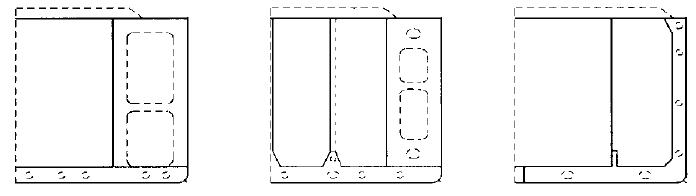
Type I ships
- It must be able to survive assumed damage anywhere in their length. Cargo tanks for the most dangerous products should be located outside the extent of the assumed damage and at least 760mm from the ship’s shell.
- IMO type 1, 2 and 3. Other cargoes, which present a lesser hazard may be carried in tanks next to the hull – (incl diluted slops after tank washings)
See layout below–
- Some of the chemicals carried on type one ships are Chlorosulphonic acid, Dodecyl phenol, Phosphorous yellow/ white, Tricresyl Phosphate (>1% ortho-isomer), Trixylyl Phosphate.
- Maximum tank size is 1250 M3.
- Double side width B/5 or 11.5 mtrs whichever is less.
- DB depth B/15 or 6 mtrs at centre line, but not < 760mm.
- Auto ignition temperature of cargoes <65 deg C.
- Explosive range >50% by volume in air.
- Type 1 offers highest limit of containment.
Type II ships
- If more than 150m in length, must be able to survive assumed damage anywhere in their length; if less than 150m, the ship should survive assumed damage anywhere except when it involves either of the bulkheads bounding machinery spaces located aft. Tanks for Type II cargoes should be located at least 760mm from the ship’s shell and outside the extent of assumed grounding damage.
- Maximum tank size is 3000 M3.
- Capable of stripping tanks <100 litres.
- Auto ignition temp of cargoes <200 deg C.
- Explosive range >40% by volume in air.
Type III ships
- If more than 125m in length, should be capable of surviving assumed damage anywhere in their length except when it involves either of the bulkheads bounding the machinery space. If less than 125m in length, they should be capable of surviving damage anywhere unless it involves machinery spaces. There is no special requirement for cargo tank location. No limit for size of tank.
- Capable of stripping tanks <300 litres with tolerance of 50 litres.
- Length > 125 m but < 225 m damage anywhere in length except including ER bulkheads.
- Length <125 m damage anywhere in length except machinery space
After 1 January 2007 vegetable oils are carried in chemical tankers complying with the revised IBC Code as a Ship Type-2 (double hull) with COF as Cat Y.
Chemical Tankers: P & A Manual
- MARPOL Annex II requires that each chemical tanker be provided with a P&A Manual to achieve compliance with the regulations and to be able to demonstrate that compliance has been considered from the earliest design stage. The format of the P&A Manual and its contents must be as specified in MARPOL Annex II Appendix D, and be approved by the flag administration of the ship.
- The P & A Manual is concerned with the marine environmental aspects of cleaning of cargo tanks, and the discharge of cargo residues that may or may not be mixed with a washing medium. The results of the stripping test are recorded in it.
- Ships’ officers should familiarise themselves thoroughly with the P&A Manual, and adhere at all times to operational procedures with respect to cargo handling, tank cleaning, stop handling, residue discharge, ballasting and deballasting. The master is obliged to ensure that the ship does not discharge into the sea any cargo residues, or mixtures of residue with water, unless such discharges are made in full compliance with the operational procedures contained in the P&A Manual, and that the equipment required by the Manual for such discharge is used.
- The P & A Manual, together with the cargo record book and Certificate of Fitness, will be checked by the ship’s own flag administration and by port state control officers in order to confirm full compliance with the requirements of MARPOL Annex II.
- It is now recognised that almost any discharge from a ship into the surrounding environment needs to be carefully considered in advance. Not only are chemical cargo residues, oily water from machinery room bilges and overboard disposal of garbage strictly regulated, but funnel exhausts and ballast water have now been identified as requiring control.
Cargo Related Documents required on board Chemical Tankers:
Transportation of chemicals by tankers is usually accompanied by considerable documentation. Documentation can be even greater when trading to and from less developed countries. The vessel’s management is presented with a great deal of documentation from parties to the cargo, authorities, etc. Furthermore vessel’s management must also issues papers serving to record evidence, claims etc.
Following are most needed documents:-
- Deck Log Book
- Sea Passage Report
- Port Log
- Notice of Readiness
- Dead freight Statement
- Protest of Difference Between Ship and Shore Figures
- Pre arrival and Commencement – Cargo Operations Checklist
- During Loading Ops Checklist
- Completion of Cargo & Pre-departure Checklist
- Prior to Use of Vapour Emission Control System Checklist
- During Discharge Ops Checklist
- Ullage Report
- Pumping Record
- Cargo Heating Report
- Inert Gas Log
- Tank Cleaning Record
- ROB Report
- Dry receipt
- Vessel Experience Factor (Load)
- Cargo Loading Plan
- Cargo Discharge Plan
- Chemical & Physical Properties
- Pressure Log & O2 Log
- Cargo Hose Record
- Cargo Sampling Log
- Tank Cleaning Plan
- Tank Cleaning Schedule Checklist
- Monitoring During Cleaning Operations
- Wall Wash Test Results
Documents provided by the Shipper:-
- Cargo quality certificate (analysis report)
- Cargo quantity certificate.
- Certificate of origin.
- Cleanliness report.
- Heating instructions.
- Inhibitor certificate.
- Cargo manifest.
- Vessel’s experience factor.
- Tank History.
- Sample receipt.
- Custom Clearance Reports / Papers
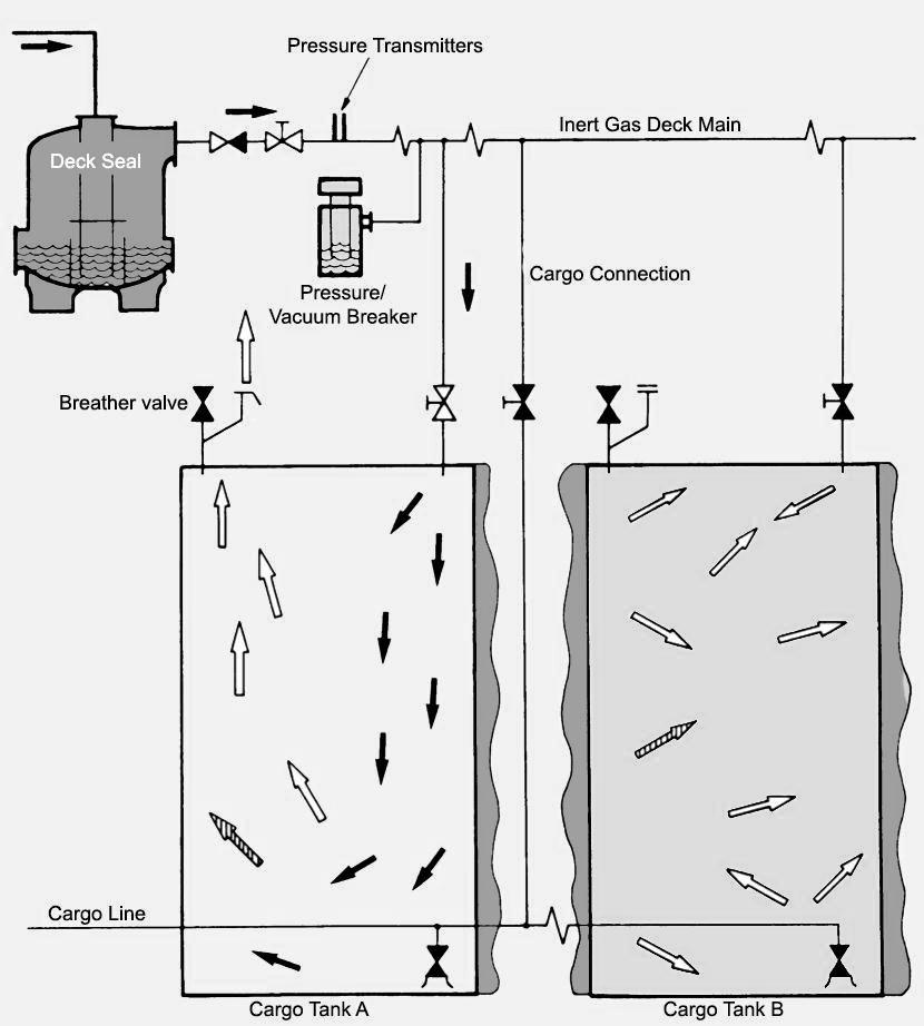
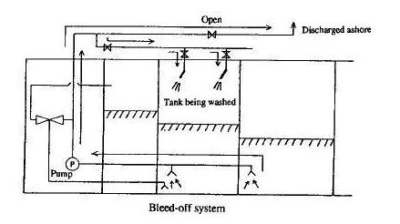
Diagram, a ‘closed circuit’ loading operation, using a vapour return line on Chemical Tankers under the provision of IBC Code:
Closed loading guideline for various noxious liquid chemicals in bulk:
- Special precautions are necessary onboard a chemical tanker during closed loading of various grade liquid chemicals.
- Closed loading/discharge means loading or discharging with securely closed ullage, sounding and sighting ports. Additionally the venting must be controlled. Vessels equipped with a system such as Skarpenord (pressure gauges in the tanks) or radar ullage systems shall at all times carry out closed loading/unloading procedures for all cargoes. Closed loading should be used at all times unless not possible due to the design of the vessel or trade practices (e.g. vegetable oil trade loading over the top is normal.)
- For gauging e.g. ullaging and sounding closed devices must be used. The level alarm systems must be operated during the entire closed cargo operation. Closed cargo operations must be stopped as soon as any essential system for safe loading or discharging becomes inoperative. Sampling to be carried out with closed sampler whenever possible. When more than one grade of cargoes is loaded, use of same sampler for different grades will contaminate the cargo sample unless the sampler has been thoroughly cleaned.
Gauging, sounding and sampling:
- A closed gauging device penetrates the cargo tank, but is part of a closed system and prevents the cargo or its vapour being released. Examples are the float-type systems, radar systems, electronic probe, magnetic probe and protected sight-glass.
- For sampling and sounding, the Dovianus or Hermetic portable gauging and sampling systems may be used. It is important that sufficient of these devices are carried onboard and maintained in a fully operational and certified calibrated condition. The vessel must fully comply with ISGOTT “Measuring and Sampling Non-Inerted Tanks” and ISGOTT “Measuring and Sampling Inerted Tanks” as applicable.
- Vapour locks, where fitted, are to be calibrated and certified by a recognised cargo inspection company which will also approve the datum level corrections including list and trim corrections for tank volumes. The approval certificate is to be readily available during cargo surveys.
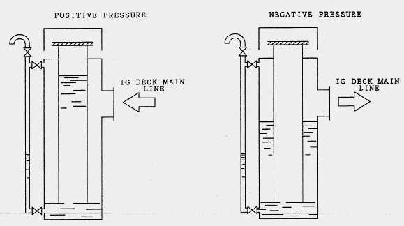
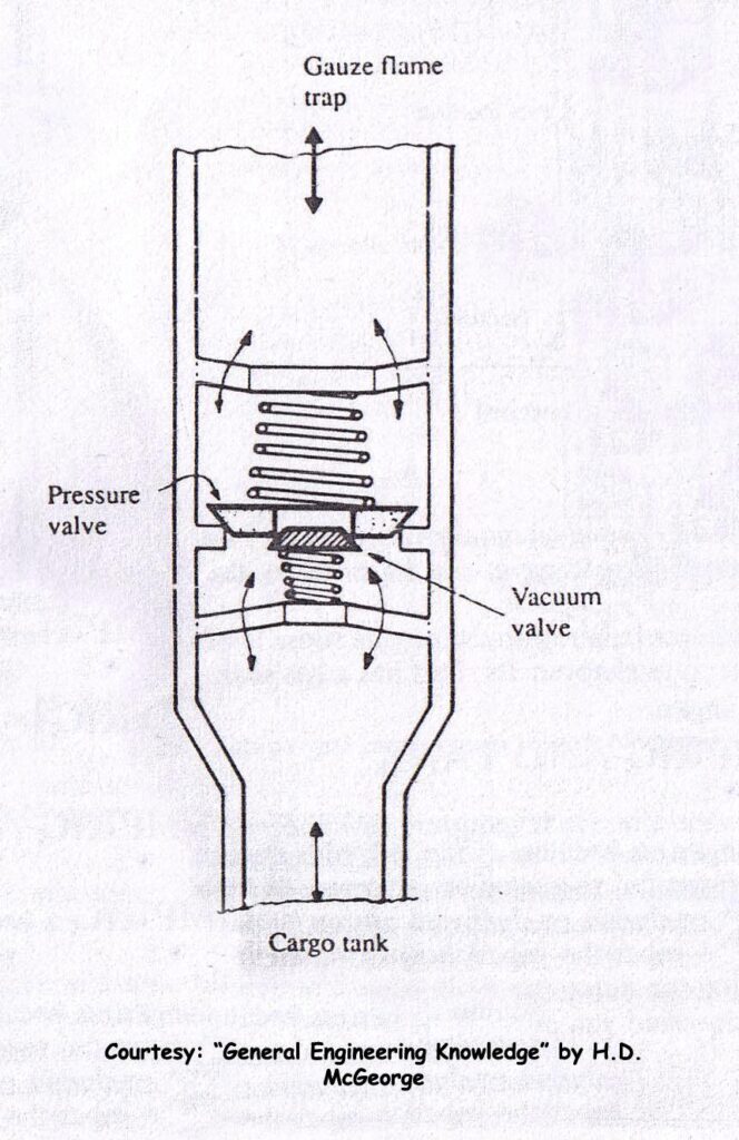
Cargo tank venting:
- Controlled venting must be established if closed cargo operations are required. A controlled tank venting system is a system with pressure and vacuum-relief valves (P/V-valve) fitted on each tank in order to limit the pressure or vacuum in the tank. The P/V valve should operate in such a manner that neither pressure nor vacuum is created in the cargo tank during cargo operations that exceed the tank design parameters.
- Secondary venting system must also be operational Information on maximum loading rates and venting capacities is to be readily available and displayed in the cargo control room.
Vapour emission control system onboard chemical tankers:
- Where required, VEC is to be used and operated in accordance with IBC Code, local regulations, and instructions contained in the vessel’s VEC System Operation Manual and in conjunction with the requirements and provisions of the shore installation.
- Masters and Officers must be aware that significant operational and safety implications are present, as the shore and the ship are effectively joined together as one unit.
The Primary Hazards include:
- The ship loses effective control of the tank atmosphere pressure, and is directly influenced by any changes which may occur within the terminals system.
- Associated pressure sensing devices on the vessel are well maintained.
- It is also essential that individual cargo tank P.V. valves are properly maintained and operate correctly.
- Check that the VECS alarms are correctly set and tested. (Secondary PV alarms are set 5-10% above PV valves setting as per Oil Major Requirements for normal operations).
- Whenever any of these alarms activates during cargo operations, the cargo operations shall be immediately stopped and cause of alarm activation rectified before resuming cargo operations.
- Vessels fitted with a VEC system must have an independent overfill alarm providing audible and visual warning. These are to be tested at the tank to ensure their proper operation prior to commencing loading, unless the system is provided with an electronic self-testing capability. Fixed gauging systems must be maintained in a fully operational condition at all times.
- The ship’s system is to be provided with means to collect and drain condensed vapour, which may have accumulated in the pipelines. Drains must be installed at low points within the ship’s piping system. These drains must be checked clear before each use of the VEC system and on a regular basis when the system is not in use.
- Care must be taken to ensure that no possibility of misconnection of Vapour and Liquid hoses can occur. The ship’s vapour connection is to be clearly identified. The outboard 1.0 metre of piping is to be painted with yellow and red bands (0.1m red, 0.8m yellow, 0.1m red) and marked with the word “Vapour” (not less than 50mm high). The vessel’s presentation flange is to be fitted with a stud to prevent an incorrect connection.
- To prevent electrostatic build up within the vapour return pipe work, all pipe work is electrically bonded to the hull. The integrity of these connections is to be periodically checked.
- VECS manual requirements to complied with respect to loading rate, vapour density, pressure drop etc.
- The full procedures for the use of the VEC system are to be clearly agreed at the pre-transfer meeting between the Terminal Representative and the Chief Officer.
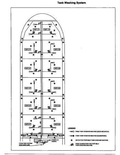
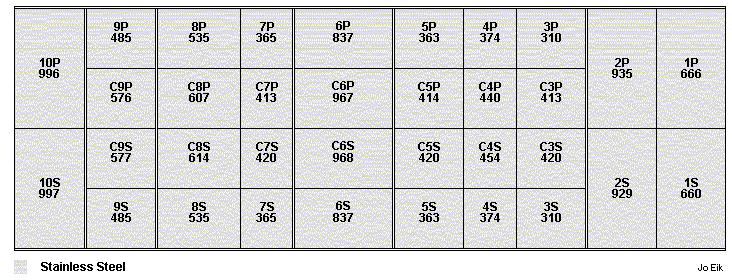
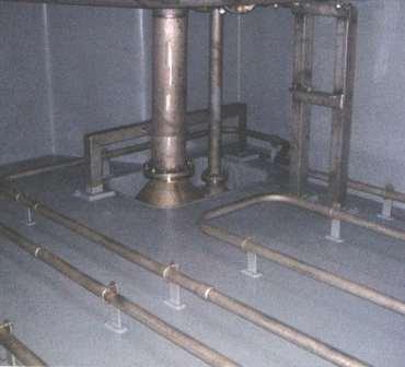
Typical tank & Piping Arrangement of any one type of Chemical Tanker:
The pipes leading from the cargo tanks to the pumps are termed as bottom lines, from the pump-room up to deck are called risers. The lines on deck are termed as deck lines. The lines which lead from the deck to the tanks are called drop lines. Besides these, there are Crude Oil washing lines on deck (COW lines). The COW main line usually branches off from the main discharge line in the pump-room. It further branches out to the various tanks on deck. There is also a small diameter line (Marpol line) which is used to discharge the last part of the cargo from the ship.
In the cargo tanks, the pipes terminate in a bellmouth. A tank may have two bellmouths – one main and one smaller stripper bellmouth. Alternatively, one bellmouth may serve the purpose of main as well as stripping discharge.
The piping system has evolved over the years to cater to varying cargo requirements. In a product tanker which is designed to carry many grades, we see that there are many more pipes so that many grades can be catered to. In a crude oil tanker, the piping is straightforward and simple.
There are three basic types of pipeline systems:
- Direct Line system
- Ring main system
- Free flow system.
Each system has their uses and is designed to fulfill a need in a particular type of vessel.
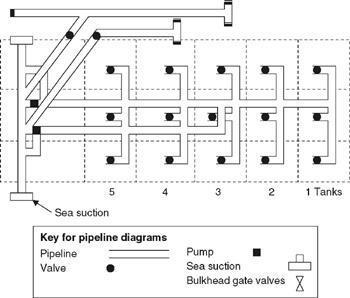
Direct Line system:-
It consists of lines running longitudinally in the centre tanks and branching out to bellmouths in the centre and wing tanks. The system is uncomplicated and found on some crude carriers.
Procedure for Tank Cleaning a Cargo Tank in a Chemical Tanker:
No cleaning can take place unless the mandatory prewash as required by MARPOL is done.
The master must enforce precautions like “no smoking “and “AC on recirc “. It is important for all on a chemical tanker to know the location of AC fresh air intake, and the Anemometer, to use the relative wind direction to advantage. Bio accumulative vapours and carcinogenic fumes can enter the engine room via intake vents and cause health problems for the engine staff. It is not all right to say that just the deck crew are exposed to toxic vapors.
Water washing can be done even if the solubility of the chemical in water is low to as much as 0.3%. such solubility always increases if the water temperature is higher. Hence always try to use wash water at high temperature ( about 25 deg higher than MP after removing cold ballast interface ) unless the cargo being cleaned does not allow it, like drying oils and mineral oils with high paraffin content. Solidified matter when melted flows away with the stripped out water, it need not be soluble.
Mineral oils with high paraffin content and certain crude oils which require heating during transportation should always be cleaned with ambient wash to prevent evaporation of lighter fractions which would leave a waxy residue on tank bulkheads.
Drying oils if prewashed with hot water will polymerize. Drying oils must be washed immediately after dischg with ambient water. If they are left to dry polymerization takes place due to reaction with oxygen, and heat increases the reaction speed. This means by removing the air form the tank using Nitrogen this process can be slowed down. By the way, Ambient means upto 35 deg C. Moderate means upto 60 deg. Hot means >60 deg C.
Certain cargoes like acetic acid, benzene, luboils, caustic soda, paraffin, molasses, phenol, DINP, fatty alcohols, HMD , Hitec, WPAC, butyl acrylate , creosote etc can be hot pre-washed.
However, if you hot prewash Styrene monomer or Acrylic acid polymerization will happen. The hotter the water, the faster the polymerization. Due to condensation of vapour, inhibitor free liquid is formed, as the inhibitor is not volatile. Inhibitor if not removed will affect the PTT test.
When a cargo is fully soluble in water, using tank cleaning chemicals in a mindless manner does more harm than good.
Cleaning the tanks is just not enough. Most often it is the tank appendages which cause huge cargo claims or tank rejection. PV valves, vent lines, fixed pipelines , portable manifold hoses, superstrip lines, sampling and drain cocks, air/ nitrogen/ steam portable connection stubs, pump internals , cofferdams –all can hold contaminant matter. With certain cargoes like LSHW FO even the butterfly valve Teflon seals can trap sludge and discolor the next cargo.
Washing tanks with portable/ fixed Butterworth machines from designated areas may not clean everything. This is why it is important to enter the tank and have a visual check before wasting fresh water and expensive tank cleaning chemicals after high MP cargoes like palm oil fatty acids. As soon as you open the tank dome you get a general idea of shadow areas.
The chief officer must know if the tank corrugations are horizontal or vertical. Horizontal corrugations mean that fixed tank cleaning machines which cannot be given drops are ineffective. Vertical corrugations mean that the position of the Butterworth port is important.
If the previous cargo is strong smelling like Acrylates or Crude Turpentine or MTBE a smell killer can be used. Gaskets emit smell, hence they must be flushed with methanol.
STAGES OF TANK CLEANING:-
1) Precleaning with sea water:- Pre cleaning is different from MARPOL mandatory Prewash. Tank cleaning machines may have shadow sectors, and this can be rectified for main wash. Nondrying oils and fats can be steamed before the hot water precleaning.
Pre-cleaning is the first cleaning step, without cleaning agents in order to remove the majority of product residue. The cleaning temperature and the temperature of the adjacent tanks are important parameters for successful cleaning. When water is not allowed, pre- cleaning is carried out with a suitable solvent. Pre-cleaning generally takes several hours and the sooner pre-cleaning is done after discharge, the easier it is to remove the product residue. Pre-cleaning is very important, because it is very difficult to obtain a satisfactory result following an initial mistake
2) Main wash with sea water: – Do not attempt to use tank cleaning chemicals unless the cargo clingage is removed.
3) Tank Cleaning Chemical wash: – If cargo is not water soluble or residues remain , the use of tank cleaning chemicals is justified. If the previous cargo is not water soluble using a 0.04% detergent wash will be good enough for WW standard ( this is not WALL WASH ). Graco barrel pump injecting into the tankcleaning line , is the best as the bottom can be kept stripped and tank cleaning chemical is not reused. Inject at the rate of 2 litres chemical per cubic meter of wash water. Discharge from both sides of the manifold to Annex 2 UW overboard.
Recirc using spider / octopus will clean dirty areas, but they will also dirty clean areas. Also if the solvent is volatile it will evaporate. Recirc is more effective after a Graco injection wash. Prevent static charge dangers. Annex 1 mineral oils which are not soluble in water requires a emulsifier/ degreaser wash. Handspray with undiluted chemicals is only for local application, sufficient contact time must be allowed.
Most cleaning agents are additives which are used in combination with water to improve the water solubility of the cargo to be cleaned. Only very few cargoes which cannot be cleaned with water-based systems require a non-water-based solvent as a cleaner (sometimes in combination with an emulsifier).
To neutralize the odor of some chemicals, the use of an odor remover may be recommended in combination with an emulsifier. For most cargoes a variety of cleaning agents are available. Cleaning agents must be IMO-approved. Cleaning concentrations, times and temperatures in the final cleaning steps are recommended in the cleaning guides to achieve a satisfactory result. Cleaning generally takes several hours.
4) Rinsing with sea water:- This is done with tank cleaning machines, the main purpose is to get rid of the residues loosened up by the tank cleaning chemicals.
5) Flushing with fresh water:- This is done with tank cleaning machine using a low throughput, to remove the salt before they dry up . If you anticipate a delay , as your ship does not have a dedicated FW pump or line prevent the salt from drying up by steaming, more so on zinc adsorbent porous surface.
6) Steaming tank and pipelines (to bring level of chlorides down and wash down appendages):- Steaming is the introduction of saturated steam into the tank to evaporate volatile residue (odour removal). The steam will condense on the tank surfaces. The temperature should normally be as high as possible during steaming. This is enhanced if the adjacent tanks (including ballast tanks) are empty Steaming removes traces of volatile substances. The steam must hence be allowed to escape constantly via the PV valve.
If the chloride level of the wash water is too high, the use of steam for removal of chloride is often the only feasible option. Clearly the steam quality depends on the construction of the boiler. If the steam is used to remove chloride, the wall temperatures should be cool (in contrast to the evaporation method described above) – this results in condensation and water film running down the tank walls to wash the chlorides off.
In case of Wall wash , with low chloride specs, for optimal results the chloride content of the water must be less than 0.1 mg/ litre (distilled water, deionized water, demineralized water by microfiltration).
7) Draining tank sump:- Strip out the tank and the pump stack. Sometimes it will be necessary to use a Wilden pump and sponges to save time. Mopping reduces drying time if there are water pools on the tank bottom. Make sure no lint is left .
8) Drying tank with ventilation:- While venting please remember that warm moist air condenses on a cold surface. Ventilation removes water, moisture and odor, which is usually done by forced air circulation.
The advantages are that:
- It is easy to operate and less training of personnel is required.
- As there are fewer valves, it takes less time to set up the valve system before commencing a cargo operation.
- Contamination is unlikely, as it is easy to isolate each section.
The disadvantages are that:
- The layout is not as versatile.
- A very rigid system which makes it difficult to plan
Ring-main systems:-
- It is also called the circular system. This type of piping system provides for the handling of several different types of oil. A particular tank can be pumped out either by a direct suction line or through another line by use of a cross-over. The system is very versatile.
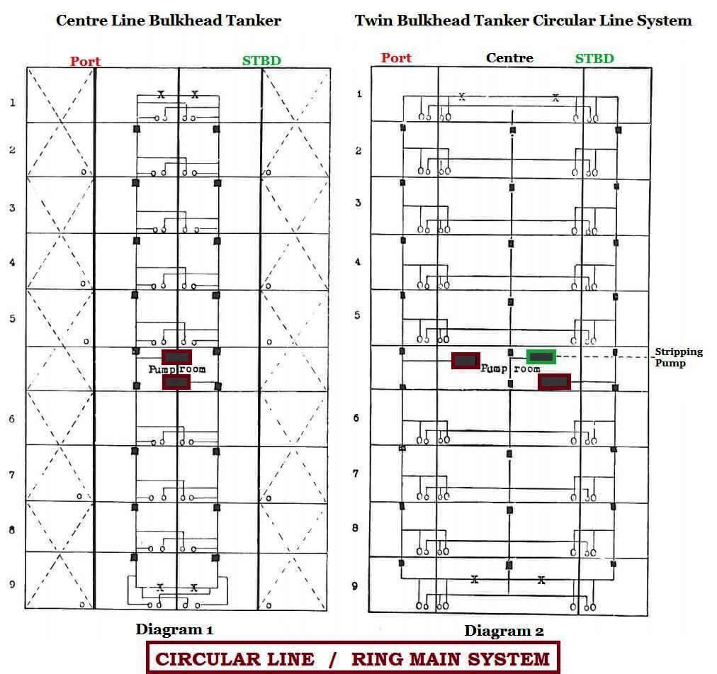
- The pipeline system illustrated above in Diagram 1 is better suited to the centre line bulkhead type of ship. Each tank or oil compartment has two suctions — one Direct suction and one Indirect suction. The direct suctions for the port tanks are all on the port cargo line, and feed the port cargo pump.
- The indirect suctions for the port cargo tanks feed the starboard cargo line and the starboard cargo pump. Master valves are provided on each line between the tanks, so as to isolate each tank from the other when necessary.
- This particular vessel is not fitted with a stripping line and pump. This type of pumping system providing for the handling of several different types of oil was a natural development from the earlier types which were only suitable for one grade of oil.
- To drain the oil from the main tanks it was necessary to list first one way, and then the other, so as to keep the strum covered and to help the flow of oil towards the suction.
- Diagram 2 shows a vessel fitted with a Circular Line or Ring Main but adjusted for the twin bulkhead type of vessel.
- This ship is also fitted with a stripping system. Inspection of the pipeline system shows that the pipeline travels around the ship in the wing tanks, crossing over from one side to the other.
- Each wing tank has a suction on the line which passes through it. The centre tanks have two suctions, one on either side leading to the port and starboard lines respectively.
- It will be noted that the master valves provide separation between the tanks as in the earlier system.
- When the level of the oil in any particular tank has fallen to a foot or less, the main pumps are switched to another full tank, and the stripping pump is brought into operation.
Free-flow system:-
- In this system, the oil flows freely into the aft most tanks when the interconnecting gate valves are opened.
- Main suction bellmouths in a full free flow tanker will only be provided in the aft tanks. However, each tank is generally provided with a small stripping line.
- This system has the distinct advantage of having lesser and less complicated piping system in the tanks and is suitable for large tankers which usually do not carry many grades of oil.
- Obviously, the flexibility of operations is comparatively less as compared to other piping systems. Some ships are also designed as part free flow i.e. free flow system only between certain tanks, which is a hybrid or cross between a full free flow system and a ring main system.
Phosphoric Acid Discharge & Tank Cleaning:
- For all cargo operations including stripping & tank cleaning procedures always refer to ship’s P & A manual.
- Phosphoric Acid is normally carried in rubber lined or Stainless Steel Tanks.
- Phosphoric Acid is generally carried on a “Type 3” Chemical tanker.
IMO Ship Type 3:- is a Chemical Tanker intended to transport products with sufficiently severe environmental & safety hazards. These products require a moderate degree of containment to increase survival capability in a damaged condition. There is no filling restrictions for chemicals assigned to Ship Type 3.
Some of the properties of Phosphoric acid is listed below:-
Pollutant Category: Z
Sp. Gravity:- 1.685 @ 25OC (Water =1 )
Vapour Pressure: 0.3 k Pa (@ 20OC)
Vapour Density: 3.4 (Air = 1)
- Easily soluble in hot water. Soluble in cold water.
- Very hazardous in case of skin contact (irritant), of eye contact (irritant) of ingestion.
- Phosphoric Acid is non-flammable.
- Reacts with metals to liberate flammable hydrogen gas.
- Minor corrosive effect on bronze. Sever corrosive effect on brass, corrosive to ferrous metals & alloys.
- Polymerization will not occur.
Tank Cleaning:-
- Ensure the prewash after dischg is with fresh water. Then use sea water till the pH is 7. Immediately after that wash again with fresh water to remove all chlorides from tank. This is crucial to avoid elephant skin.
- Any sediment at the bottom of tank can only be removed with more pure phosphoric acid like crude oil wash. It will take a long time to kew machine the cement off the bottom. So keep some good clean pac in 200 drums for this manual effort.
- Have a look at the first empty tank. If the sediment is too much –it is usual to recirc at end of discharge of each tank.
- Acid/sea water mixture remaining in lines and stainless steel hoses will soon result in pittings.
- For Stainless Steel (SS) Tanks: – After the tanks are thoroughly/finally cleaned, passivate the tanks with Nitric Acid as the Phosphoric destroys the passive oxide coating on the stainless.
- Category Z:- Noxious Liquid Substances which, if discharged into the sea from tank cleaning or deballasting operations, are deemed to present a minor hazard to either marine resources or human health and therefore justify less stringent restrictions on the quality and quantity of the discharge into the marine environment.
- Every ship constructed on or after 1 July 1986 but before 1 June 2007 shall be provided with a pumping & piping arrangements to ensure that each tank is certified for the carriage of substances in Cat X or Y does not retain a quantity of residue in excess of 900 ltrs in the tank of its associated piping.
- Similarly each tank certified for the carriage of substances in Cat Z does not retain a residue of quantity in excess of 300 ltrs in the tanks and associated piping.
Discharge Criteria for Tank wash residues into Sea:-
- Underwater discharge criteria are applicable to all ships built after 1 Jan 2007.
- If outside any S.A. (Special Area)
- Discharge tank washing 12 NM from Nearest land.
- Depth of water must be more than 25 mt.
- Speed of ship must be more than 7 kmts.
- S.A. designated for Annex II cargoes is Antartic Region.
- Discharge of tank washings is not permitted in the Baltic Region.
IBC Code: Integral tank:
Ans:- Integral tanks: Integral Tank means a cargo-containment envelope which forms part of the ship’s hull and which may be stressed in the same manner and by the same loads which stress the contiguous hull structure and which is normally essential to the structural completeness of the ship’s hull.
IBC Code: Gravity tank. (July-18)
Ans:- Gravity tank: Gravity tank means a tank having a design pressure not greater than C). 7 bar gauge at the top of the tank. A gravity tank may be independent or integral. A gravity tank should be constructed and tested according to recognized standards, taking account of the temperature of carriage and relative density of the cargo.
IBC Code: Pressure tank. (July-18)
Ans:- Pressure tank: Pressure tank means a tank having a design pressure greater than 0.7 bar gauge. A pressure tank should be an independent tank and should be of a configuration permitting the application of pressure-vessel design criteria according to recognized standards.
Hazards involved with Tank Cleaning in Type 1 Chemical Tankers:
A Hazard is a physical situation with a potential for human injury, damage to property, damage to the environment, to capital investment or some combination of these. Hazards can be identified through a review of the Physical Properties and Product Characteristics of the product to be cleaned.
- Fire & Explosion Three elements are necessary to create a fire: Fuel, an Oxidiser (usually air) and a Source of Ignition (energy). In theory, ignition is not possible, if any one of the 3 is eliminated. Most cleaning operations will be carried out in tanks that are filled with air, thus the oxidiser is present in most cases, unless the tank is inerted. Fuel as far as tank cleaning is concerned could be the product itself, if this product has a low flash point, or a flammable cleaning solvent. Under certain circumstances even substances with a high flash point can be ignited and must thus be considered as a fuel (mist). During many tank cleaning operations the atmosphere in the tank must be considered as flammable because the product to be cleaned is flammable and inertisation is not possible. Under these circumstances the only way to guarantee that an explosion cannot occur during cleaning is to make certain that there is no source of ignition. A potential source of ignition during tank cleaning is Electrostatic discharge. Especially during water spraying electrostatic charges could be induced.
- Undesired reactions Polymerization (Depletion of inhibitor or excessively high temperature) Saponification (Creation of hard soap forming a layer on the tank requiring acid cleaning or even removal by Hydroblasting) Drying/Hardening (Formation of hard debris that is no longer soluble, requiring treatment with a Solvent) Reaction with water (Violent reaction of an Isocyanate after Pre-Cleaning with water)
- Corrosion – Corrosive substances destroy human tissue on contact (e.g. skin, eyes and mucous membranes in the mouth and respiratory tract) Metal or other material used in ship construction could be corroded at an excessive rate.
- Overexposure to toxic substances (Death of operator after wiping Phenol residues by tank entry without wearing a full chemical suit and SCBA [self-contained breathing apparatus])
- Asphyxiation – Oxygen deficiency (Entry into a tank with an inert gas atmosphere)
- Emissions
- To the air: As always when ventilating, special care must be taken to prevent the risk of explosion (flammable products) or with regard to toxic vapors. All normal safety precautions must be taken. (No smoking, accommodation ventilation on recirculation etc.) The wind strength and wind direction must also be a decisive parameter for the Master to allow ventilation. To avoid a buildup of explosive or toxic vapors on deck the amount of gas to be escaped from the tanks should be limited. Never open and ventilate several tanks at the same time.
- To the water: Emissions to the water should be reduced to the absolute minimum. All on-board facilities must be operated carefully according to the P&A Manual to reduce the residues during unloading. All regulations, especially MARPOL I and II, must be followed strictly.
Certificate Of Fitness (COF) on Chemical Tankers:
- An International Certificate of Fitness for the Carriage of Dangerous Chemicals in Bulk shall be issued after an initial or renewal survey to a chemical tanker engaged in international voyages which comply with the relevant provisions of the Code.
- Classification society issues the certificate of fitness on behalf of the administration.
- An International Certificate of Fitness for the Carriage of Dangerous Chemicals in Bulk shall be issued for a period specified by the Administration which shall not exceed 5 years.
- All ships will get a new COF after 1.1.07, considering IBC code and Marpol rules are revised as on 1.1.07. IMO has decided that Chemical carriers can carry COF or NLS, not both.
- Ships with COF can carry IBC code chapter 17 XYZ cargoes also —– while NLS certificated ships an carry IBC code Chapter 18, Category Z and OS cargoes only.
- For ships carrying IBC code chapter “Other Substances” OS, there is no need for COF, they require only NLS certificate.
- COF is a certificate issued by Flag administration confirming that the structure, equipment and materials used in the construction of the chemical tanker are in compliance to carry a given list of chemicals and it gives the conditions of carriage.
- Upon receipt of cargo loading instructions, all products are to be checked against the Certificate of Fitness. Any irregularities are to be reported immediately to the chemical operator. However, it must be understood that this by itself is not enough. The tank lining resistance tables must be consulted and only if both agree can the chemical be considered to be loaded.
- Since new chemicals are being manufactured and re-evaluated for safe sea carriage regularly it may be possible that some chemical is not included in the COF list. In such a case permission may be obtained from flag administration or their representative for this particular chemical and attached to the COF as an addendum.
- The issuance of an Addendum to CoF may be done immediately based on the Tripartite Agreement. The submission of data and evaluation by GESAMP and ESPH may come afterwards.
Cargo tank coatings can be categorized into two main groups:
Inorganic coatings – zinc silicates and ethyl silicate types.
Generally, the life of this coating is proportional to the thickness of the coat. This coating is one-layer coating, comprising of inorganic silicates pigmented with high percentage of zinc powder.
Organic coatings – epoxy and modified epoxy systems.
This type of coating consists an organic resin system, which form strong chemical bonds between the resin molecules. Those types of coating have the ability to resist in more strong acids or alkalis than inorganic coatings. And they tend to absorb significant quantities of cargo and contamination problems can occurs.
Coating Systems and Types:
Numerous types of coating have been used for cargo tank service in sea trades. Some of these coating have stopped to being used. And more reliable and flexible coating has been developed. Typical coating system can be categorized as Zinc and Epoxy coating
Zinc Silicates:- Zinc silicates are formulation of zinc powder plus organic or inorganic binder, and designed to be porous films, which can create problem in the tank cleaning process especially when vessel carry non-volatile cargoes.
Main Characteristic:
- Not resistant to strong acid or bases, including sea water which has a slow weakening effect
- High resistance and tolerance to aromatic hydrocarbon solvent, alcohols and ketones
- Volatile cargoes are desorbed very fast, and retain non-volatile oil like cargoes.
- Residues can result in contamination of next or after next cargo
Epoxy:
Generally suitable for the carriage of alkalis, animals fats and vegetable oils but they have limited resistance to aromatics such as benzene and toluene, alcohols such as ethanol and methanol
Main Characteristic:
- Resistant to most strong acids and bases
- Do not retain oil like cargoes. Solvent cargoes are absorbed
- Water wash before thorough ventilation and desorption of residues could result in serious damage of the coating
- Residues can result in contamination of next or after next cargo
- Suitable for carriage of animal fats and vegetable oils provided the free fatty acid content of 5%.
Coatings are required for any cargo tank which constructed from mild steel. Most of BLT Chembulk Group modern chemical fleet is SUS cargo tank. SUS are good materials for chemical tanks, because of their ability to create a passive layer on their surface. This passive layer is mainly consisted by chromium oxide, which is very resistant to corrosive environment.
However, in some environments like strong hot acids, chloride solutions and generally solutions which contain halogens, the passive film can break down locally and new film formulation can be disrupted. Generally, SUS is considered to be the ideal material of construction because it’s non-corrosive and easy to clean.
Hazards associated with Carriage of Chemicals:
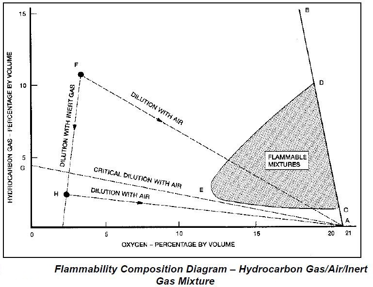
- FLAMMABILITY:
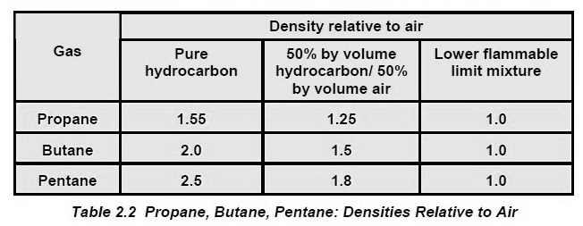
- Vapour given off by a flammable liquid will burn when ignited provided it is mixed with certain proportions of air, or more accurately with the oxygen in air. But if there is too little or too much vapour compared to the air, so that the vapour-and-air mixture is either too lean or too rich, it will not burn. The limiting proportions, expressed as a percentage by volume of flammable vapour in air, are known as the lower flammable limit (LFL) and the upper flammable limit (UFL), and the zone, in between is the flammable range (see Definitions for further details).
- In addition, a flammable liquid must itself be at or above a temperature high enough for it to give off sufficient vapour for ignition to occur. This temperature is known as the flash point. Some cargoes evolve flammable vapour at ambient temperatures, others only at higher temperatures or when heated. Safe handling procedures depend upon the flammability characteristics of each product. Non-combustible cargoes are those which do not evolve flammable vapours
- Volatile and Non Volatile Cargoes.
- If a cargo is being handled at a temperature within 10C of its flashpoint, it should be considered volatile.
- Therefore a cargo with a flashpoint of 80C should be considered volatile if handled at a temperature of 70C or above.
- HEALTH HAZARDS:
- Toxic means the same as poisonous. Toxicity is the ability of a substance, when inhaled, ingested, or absorbed by the skin, to cause damage to living tissue, impairment of the central nervous system, severe illness or, in extreme cases, death. The amounts of exposure required to produce these results vary widely with the nature of the substance and the duration of exposure to it.
- Acute poisoning occurs when a large dose is received by exposure to high concentrations of a short duration, i.e. a single brief exposure. Chronic poisoning occurs through exposure to low concentrations over a long period of time, i.e. repeated or prolonged exposures. Prevention of exposure is achieved through a combination of cargo containment, which prevents toxic fumes or liquid from contaminating the workplace, and the use of personal protective equipment (PPE)
- Suffocation: suffocation is unconsciousness caused by lack of oxygen, Any vapour may cause suffocation, whether toxic or not, simply by excluding oxygen in air. Danger areas include cargo tanks, void spaces and cargo pumprooms. But the atmosphere of a compartment may also be oxygen-deficient through natural causes, such as decomposition or putrefaction of organic cargo
- Anaesthesia: Certain vapours cause loss of consciousness due to their effect on the nervous system. In addition, anaesthetic vapours may or may not be toxic.
- Additional health hazards: Additional health hazards may be presented by non-cargo materials used on board during cargo handling. One hazard is that of frostbite from liquid nitrogen stored on board for use as atmosphere control in cargo tanks. Full advice on dealing with frostbite is contained in the MFAG. Another hazard is that of burns from accidental contact with equipment used while handling heated cargoes.
- REACTIVITY
- Self Reaction:
- The most common form of self-reaction is polymerisation. Polymerisation generally results in the conversion of gases or liquids into viscous liquids or solids. It may be a slow, natural process which only degrades the product without posing any safety hazards to the ship or the crew, or it may be a rapid, exothermic reaction evolving large amounts of heat and gases. Heat produced by the process can accelerate it. Such a reaction is called a run-off polymerisation that poses a serious danger to both the ship and its personnel. Products that are susceptible to polymerisation are normally transported with added inhibitors to prevent the onset of the reaction.
- An inhibited cargo certificate should be provided to the ship before a cargo is carried. The action to be taken in case of a polymerisation situation occurring while the cargo is on board should be covered by the ship’s emergency contingency plan.
- Reaction with water: Certain cargoes react with water in a way that could pose a danger to both the ship and its personnel. Toxic gases may be evolved. The most noticeable examples are the isocyanates; such cargoes are carried under dry and inert condition. Other cargoes react with water in a slow way that poses no safety hazard, but the reaction may produce small amounts of chemicals that can damage equipment or tank materials, or can cause oxygen depletion.
- Reaction with air: Certain chemical cargoes, mostly ethers, may react with oxygen in air or in the chemical to form unstable oxygen compounds (peroxides) which, if allowed to build up, could cause an explosion. Such cargoes can be either inhibited by an anti-oxidant or carried under inert conditions.
- Reaction with other cargoes: Some cargoes react dangerously with one another. Such cargoes should be stowed away from each other (not in adjacent tanks) and prevented from mixing by using separate loading, discharging and venting systems. When planning the cargo stowage, the master must use a recognised compatibility guide to ensure that cargoes stowed adjacent to each other are compatible.
- Reaction with other materials: The materials used in construction of the cargo systems must be compatible with the cargo to be carried, and care must be taken to ensure that no incompatible materials are used or introduced during maintenance (e.g. by the material used for replacing gaskets). Some materials may trigger a self-reaction within the product. In other cases, reaction with certain alloys will be non-hazardous to ship or crew, but can impair the commercial quality of the cargo or render it unusable.
- Self Reaction:
- CORROSIVENESS:
- Acids, anhydrides and alkalis are among the most commonly carried corrosive substances. They can rapidly destroy human tissue and cause irreparable damage. They can also corrode normal ship construction materials, and create a safety hazard for a ship. Acids in particular react with most metals, evolving hydrogen gas which is highly flammable. The IMO Codes address this, and care should be taken to ensure that unsuitable materials are not included in the cargo system. Personnel likely to be exposed to these products should wear suitable personal protective equipment.
- PUTREFACTION:
- Most animal and vegetable oils undergo decomposition over time, a natural process known as putrefaction (going off), that generates obnoxious and toxic vapours and depletes the oxygen in the tank. Tanks that have contained such products must be carefully ventilated and the atmosphere tested prior to tank entry.
- It must not be assumed that all vapours produced by cargoes liable to putrefaction will in fact be due to putrefaction; some may not be obvious, either through smell or appearance of the cargo. Carbon monoxide (CO), for instance, is colourless and odourless and can be produced when a vegetable or animal oil is overheated.
- Vapour given off by a flammable liquid will burn when ignited provided it is mixed with certain proportions of air, or more accurately with the oxygen in air. But if there is too little or too much vapour compared to the air, so that the vapour-and-air mixture is either too lean or too rich, it will not burn. The limiting proportions, expressed as a percentage by volume of flammable vapour in air, are known as the lower flammable limit (LFL) and the upper flammable limit (UFL), and the zone, in between is the flammable range (see Definitions for further details).
- In addition, a flammable liquid must itself be at or above a temperature high enough for it to give off sufficient vapour for ignition to occur. This temperature is known as the flash point. Some cargoes evolve flammable vapour at ambient temperatures, others only at higher temperatures or when heated. Safe handling procedures depend upon the flammability characteristics of each product. Non-combustible cargoes are those which do not evolve flammable vapours
- Volatile and Non Volatile Cargoes.
- If a cargo is being handled at a temperature within 10C of its flashpoint, it should be considered volatile.
- Therefore a cargo with a flashpoint of 80C should be considered volatile if handled at a temperature of 70C or above.
Contents of Procedure and Arrangements (P & A) Manual as required under Annex II of Marpol 73/78:
MARPOL Annex II requires that each ship which is certified for the carriage of Noxious Liquid Substances in bulk shall be provided with a Procedures and Arrangements Manual. Scope of this plan is to provide the arrangements and equipment required to enable compliance with MARPOL Annex II. Plan is developed in line with IMO Legislation. Approval by the Administration or a Recognised Organisation (RO) on behalf of the Administration is mandatory.
Indicative Contents:
- Main Features of Marpol 73/78, Annex II
- Description of The Ship’s Equipment And Arrangements
- Cargo Unloading Procedures And Tank Stripping
- Procedures Relating To The Cleaning of Cargo Tanks, The Discharge of Residues, Ballasting And Deballasting
- Flow Diagrams & Drawings
- Heating requirement of cargo
- Control of heating system
- Method of temperature measurement
- Stripping requirement for the ship
- Cleaning & disposal procedure
- Prewash procedure
- Prewash for solidifying substances
- Minimum quantity of water to be used
- Required duration of prewash
- Ventilation procedure
Table showing Control of Discharge of Category X, Y & Z NLS as per Marpol Annex II:
Marpol Annex II – Discharge Criteria:-
| Category | BCH Ships Constructed before 31/7/1986 | Existing IBC Constructed from 31/7/1986 but before 1/1/2007 | New Buildings Constructed from 1/1/2007 | Ships Other than Chemical Tankers Constructed before 1/1/2007 |
| X | Pre-Wash Strip to 350 Litres 12 mile 25m water depth 7 knots, en-route | Pre-Wash Strip to 150 Litres 12 mile 25m water depth 7 knots en-route | Pre-Wash Strip to 75 Litres 12 mile 25m water depth 7 knots, en-route | Carriage Prohibited |
| Y | Pre-Wash for Solidifying for high viscosity substances Strip to 350 Litres 12 mile 25m water depth 7 knots, en-route | Pre-Wash for solidifying for high viscosity substances Strip to 150 Litres 12 mile 25m water depth 7 knots, en-route | Pre-Wash for solidifying for high viscosity substances Strip to 75 Litres 12 mile 25m water depth 7 knots, en-route | Carriage Prohibited |
| Z | Strip to 950 Litres 12 mile 25m water depth 7 knots, en-route | Strip to 350 Litres 12 mile 25m water depth 7 knots, en-route | Strip to 75 Litres 12 mile 25m water depth 7 knots, en-route | Strip to Maximum Extent 12 mile 25m water depth 7 knots, en-route |
| OS | No carriage Requirements | No Carriage Requirements | No Carriage Requirements | |
| Underwater Discharge Required | Only X and Y cargoes | Only X and Y cargoes | X, Y and Z cargoes |
WRT to above table, discharge of residues of category X for ship constructed before 31 July 1986.
- Stripping to 350 Ltrs
- Pre-Washed
- The resulting residues to be discharged to the reception facility.
- The concentration of substance in effluent must be at or less than 0.1% by weight.
- Ship proceeding enroute with speed of atleast 7 kts.
- More than 12 NM from nearest land.
- Depth of water not less than 25 mtrs.
- Discharge is made below the water line.
- P & A Manual shall be referred.
Contents of SMPEP manual and who approves it:
SMPEP (Shipboard Marine Pollution Emergency Plan):
Background
MARPOL Annex II Regulation 17 requires every chemical tanker of 150 GT and above to carry a SMPEP. Scope of this plan is to provide guidance on the actions to be taken if a spill of oil or noxious liquid substance has occurred or is likely to occur. The plan is in line with IMO MEPC. 54(32), MEPC. 86(44) and the SMPEP guidelines in Resolution MEPC. 85(44). Plan Approval by the Administration or a Recognised Organisation (RO) on behalf of the Administration is mandatory.
Indicative Contents
- Reporting Requirements
- Steps To Control Discharge
- National And Local Co-Ordination
- Additional Information
- List Of Coastal State Contacts
- List Of Ship Interest Contacts
- Summary of Flow Chart And Checklists
- IΜΟ Resolution A.851(20)
- Vessel Specific Information
Info/Plans Required
- Ship Specific Information (Questionnaire to be submitted)
- General Arrangement Plan
- Capacity Plan
- Midship Section
- Lines Plan
- Tank Tables
- Benefits
- Master will have guidance with respect to the steps to be taken when a pollution incident has occurred or is likely to occur.
- All latest legislation and contact information will be included
- Easy reporting procedure for initial and follow up report (with examples)
- Quick and simple response with actions guide and responsible personnel
- Media handling guidance
We will ensure
- Full compliance with national and international regulations and common marine practice
- Real life documentation addressed to senior officers and crew onboard
- Full integration of any client specific requirements
- Full support provided after development in line with our Document Support Policy