Medical First Aid Guide (MFAG) Introduction & Contents:
The IMO/WHO/ILO Medical First Aid Guide for Use in Accidents involving Dangerous Goods (MFAG) refers to the substance, material and articles covered by the International Maritime Dangerous Goods Code (IMDG Code), and the materials covered by Appendix B of the Code of Safe Practice for Solid Bulk Cargoes (BC Code). It is intended to provide advice necessary for initial management of chemical poisoning and diagnosis within the limits of the facilities available at sea.
This Guide should be used in conjunction with the information provided in the IMDG Code, the BC Code, the Emergency Procedures for Ships Carrying Dangerous Goods (EmS), the International Code for the Construction and Equipment of Ships Carrying Dangerous Chemicals in Bulk (IBC Code), and the International Code for the Construction and Equipment of Ships Carrying Liquefied Gases in Bulk (IGC Code).
The MFAG itself gives general information about the particular toxic effects likely to be encountered. The treatment recommended in this Guide is specified in the appropriate tables and more comprehensive in the appropriate sections of the Appendices. However, differences exist between countries on certain types of treatment and where these differences occur they are indicated in the relevant national medical guide.
Treatments in this guide cater for the accidental human consequences of the carriage of dangerous goods at sea. Accidental ingestion of toxic substances during voyage is rare. The guide does not cover ingestion by intention.
Minor accidents involving chemicals do not usually cause severe effects provided that the appropriate first aid measures are taken. Although the number of reported serious accidents is small, accidents involving those chemicals which are toxic or corrosive may be dangerous, and must be regarded as being potentially serious until either the affected person has completely recovered, or medical advice to the contrary has been obtained.
Information on the treatment of illnesses which are of a general nature and not predominantly concerned with chemical poisoning may be found in the ILO/IMO/WHO International Medical Guide for Ships (IMGS).
CONTENTS:-
Table 1 – Rescue
Table 2 – Cpr (Cardio-Pulmonary Resuscitation)
Table 3 – Oxygen Administration and Controlled Ventilation
Table 4 – Chemical-Induced Disturbances Of Consciousness
Chemical irritation of the lungs: dry cough, breathlessness and wheezing
Chemical irritation and oedema of the lungs: severe breathlessness and frothy sputum
Chemical irritation and secondary infection of the lungs: productive cough (sticky white, yellow or green phlegm [sputum])
The chemical hazards from fire
Chemical hazards from welding
Chemical hazards from explosive chemicals
Appendix 10 Ingestion Of Chemicals
Perforation of the gut and peritonitis
Appendix 11 Shock
Fainting
Circulatory collapse and shock
Heart failure
Appendix 12 Acute Kidney Failure
Appendix 13 Fluid Replacement
Oral fluids
Intravenous fluids
Rectal fluids
Appendix 14 List Of Medicines And Equipment
List of equipment
Appendix 15 List Of Substances
UN Number sortation
Alphabetic sortation
MFAG Guide:-
Information on medical first aid to be provided in the incidents involving dangerous goods is enlisted in the MFAG Guide, which is provided as a supplement in the IMDG Code.
The advice given in the guide refers to the substances materials and articles covered by the IMDG code & materials covered by Appendix B of the IMSBC Code.
It is intended to provide advice necessary for chemical poisoning and diagnosis within the limits of facilities available at sea.
The treatment recommended in this guide is specified in the appropriate tables and more comprehensive in the appropriate section of Appendices.
For the convenience of user this guide is divided into three step approach procedure:
Step 1: Emergency Action & Diagnosys.
Step 2: Table – The tables give brief instruction for special circumstances.
Step 3: Appendices – The appendices provide comprehensive information a list of medicines / drugs and list of chemicals {in alphabetical & UN No. (Numerical)} in Appendix 15.
MFAG Table No.: The “Medical First Aid Guide for Use in Accidents involving Dangerous Goods” is a supplement to the IMDG code.
After looking up the MFAG Table No., see the table in the MFAG. It gives likely signs, symptoms, treatment and other advice as per the effect of goods under that table.
It suggests treatment in case of skin contact, eye contact inhalation and ingestion. The procedures for the treatment are also mentioned.
Preparations to be carried out prior to Loading Refrigerated Cargoes:
Reefer cargo should be loaded onboard only under the supervision of a recognized surveyor.
Cargo should not be allowed to wait for long time on the quay.
Hold should be pre-cooled to temp below the carriage temp.
Damp, wet and torn packages should be inspected if the cargo has deteriorated. If the cargo is fine then only it should be loaded after re-packing.
Contents of at least 5-10% cartons should be examined from each hold on a random basis.
Cartons with soft or dripping contents should bedocume rejected.
Refrigeration of holds should be turned on during long breaks and during meal breaks.
Once loaded, the cargo should be covered with tarpaulin.
During operations, the frost formed on top of the bripe pipes should be brushed carefully. It should not fall on top of the cargo.
In tropical climates avoid loading in the noon. Try to load cargo during night time.
Upon completion of loading, the reefer chamber must be closed air tight and cooling resumed immediately.
Principle & Working of different types of Refrigerated Cargo:-
1. Closed Reefer: This is a conventional type refrigerated container. It comes in one-piece with integral front wall and an all-electric automatic cooling and heating unit for ISO sea-going containers.
2. Modified/ Controlled Atmosphere (MA/CA) reefer containers: These type of insulated shipping containers maintain a constant atmosphere by replacing consumed oxygen using an air exchange system, keeping an ideal atmosphere in equilibrium with the product’s deterioration rate.
3. Automatic Fresh Air Management Containers: Popularly known by its acronym – AFAM reefer containers uses advanced technology to regulate the air combination by automatically adjusting the scale of fresh air exchange. It works similar to Controlled Atmosphere refrigerated container, controlling the composition of oxygen, carbon dioxide and others. The controls of the AFAM refrigerated containers can be adjusted to influence and extend the shelf lives of the cargo they carry.
Maintenance / Preparation of Cargo holds on board a Reefer vessel:
Depending upon the degree of littering, different methods of cleaning are to be used; For normal carton-packed cargoes with or without dunnage, it is usually enough to sweep the compartments. After meat and fish cargoes washing is almost always necessary. Sweeping must be carefully done and all dirt removed from the compartments. The holds should be swept as they are emptied and the dirt should be removed when the cargo has been discharged. If any cartons are broken and dunnage is spread all over the compartments, the situation is more complicated.
It has to be checked that goods from the cartons are not hidden anywhere on deck beams, in remote inaccessible corners or under the gratings. In these cases it is necessary to remove every piece of grating and sweep under it. Spot washes should be done, where cargo has come loose, been damaged or treaded down into gratings.
If the holds are badly littered, a careful washing has to be performed with a high pressure machine with a suitable washing detergent for the first cleaning, where after rinsing must be done carefully. If necessary, it must be deodorised using ozone, sodium bicarbonate or patent deodorisers but strong disinfectants not be used. The high pressure jet should not be applied at right angles to clean the surface but diagonally to the surface so that the jets cut away the dirt from the surface. The prescriptions from the supplier regarding the dosis of detergent must be carefully followed.
When cleaning it must be carefully checked that the whole compartments will be cleaned on the bulkheads as well as on and under decks with special care to deck beams and girders under deck on the upper side. The gratings should be cleaned properly including the bottom side as required.
The cooler rooms which contain the blowers and coils need to be also cleaned as and when required. The trays under the coolers must be kept clean. The purpose of these trays is to collect condensed water and melted ice and if necessary leakage from the coolers.
Scuppers are to be cleaned and brine traps checked, tested and refilled. Brine traps prevent warm air from entering the compartment and cold air from escaping; at the time same time allowing drainage of water.
Bilges and scupper drains should be clean and clear. Bilge pumping arrangements should be in working order and capable of pumping each bilge dry.
During cleaning it should be checked that the air flow channels are cleaned and when carrying out repairs to them special attention should be paid that the channels are not blocked.
Return air grids should be intact and clear. The air openings between the trays and the coolers are necessary in order to let the air pass. If this space is cluttered up, the air circulation will be throttled. Air ducts should be unobstructed. Fresh air flaps or valves should be free to move. The circulation and fresh air fans should be working satisfactorily.
The covers of the cargo hold lights should be intact. The hatch cover hydraulic system should be free of leakages. The cargo holds should be free of loose rust and paint chips.
The insulation and permanent dunnage is to be checked and repaired as required.
The hatch covers should be weathertight. All the gratings should be intact. Gratings should be free of moving and/ or tilting and/or sliding. The grating decks should have an even surface (flush). All spar deck beams should be intact and the spar decks should have an even surface (flush).
Pallet suitability:- The pallet side-boards should be intact. Instructions would be received for the use of pallet side-boards. Pallet problem areas should be identified and attended to. All pallet instructions should be removed, marked or made flush.
Signs:- Hygiene signs should be placed onboard before commencement of loading. The signs `NO SMOKING’ and `USE WALKING BOARDS’ should be painted in the hatch coamings.
Reefer Machinery:- Refrigeration system should be clear of leakages. The refrigeration machinery should be in working condition and adequate for the intended voyage and the electrical generating capacity should be sufficient for the intended voyage.
Reefer Monitoring Equipment:- Delivery and return air sensors should be calibrated by an ice bucket test regularly. USDA air and pulp sensors also should be calibrated by an ice bucket test. CO2 sensors should be operating properly. The humidity sensing and recording equipment should be working properly. Thermometers should be in position and ventilator plugs to the compartment fitted in place and tightly wedged.
All openings are to be sealed against entry of air.
Brine pipes are to be tested to ensure that they are not choked and that no leaks occur at the joints
Stores Stocks:- Sufficient cargo handling materials like Walking Boards, Slings, T Bars and Air bags should be available.
360 Quality certificate:- The vessel should have a valid 360 Quality certificate.
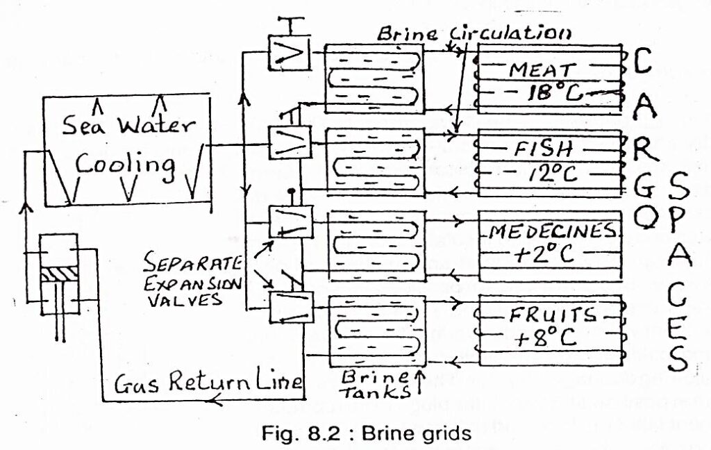
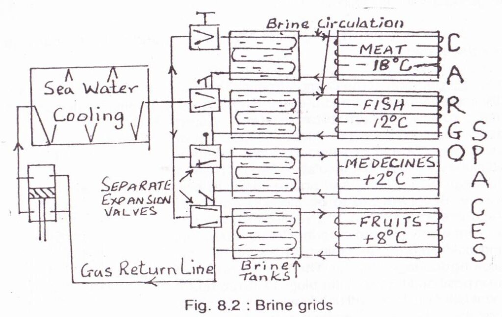
Indirect Method & Second Refrigerant (Brine Cooling) :
The primary refrigerant is used to cool a tank of brine and this cooled brine is then circulated through the compartment.
Brine is chosen because of its low freezing point, 20° to 30°C, depending on its concentration and composition.
The brine is passed through separate grids surrounding the same compartment.
If one grid is blocked or chocked, the brine supply can be increased to other grids so that cooling will not be affected.
Cooling is carried out by a combination of cold brine and cool air circulation.
Handling Reefer Cargo:
Frozen Cargo: Meat, Butter, Poultry and Fish. -8OC To -12OC
Chilled Cargo: Cheese, Eggs and Fresh Vegetables. -2OC To 6OC
Air Cooled Cargo: Fruits. 2OC to 12OC
Preparation of cargo hold:
The compartment must be clean, dry and free of any odour or taint,
Hold must be deodorised with mild agents (lime, ozone),
Bilges to be cleaned, dry, deodorised and suctions checked,
The insulation and permanent dunnage to be checked and repaired as necessary,
Scuppers to be cleaned,
Brine traps to be checked, tested and refilled,
Thermometers to be in position,
Ventilator plugs in position and tightly wedged,
Brine pipes to be tested to ensure they are not chocked and that no leaks occur at the joints.
Precooling of the compartment:
The compartment should be cooled down prior to loading to a temperature slightly lower than the transit temperature, Dunnage laid in the compartment should also be cooled down otherwise it will stain the cargo.
Precautions during loading:
Reefer cargo should be loaded onboard only under the supervision of a recognized surveyor,
Cargo should not be allowed to wait for long time on the quay,
Hold should be pre-cooled to temp below the carriage temp,
Damp, wet and torn packages should be inspected if the cargo has deteriorated. If the cargo is fine then only it should be loaded after re-packing,
Contents of at least 5-10% cartons should be examined from each hold on a random basis,
Cartons with soft or dripping contents should be rejected,
Refrigeration of holds should be turned on during long breaks and during meal breaks,
Once loaded, the cargo should be covered with tarpaulin,
During operations, the frost formed on top of the bripe pipes should be brushed carefully. It should not fall on top of the cargo.
In tropical climates avoid loading in the noon. Try to load cargo during night time,
Upon completion of loading, the reefer chamber must be closed air tight and cooling resumed immediately.
Precautions during Stowage:-
Cargo must be stowed in order to allow free circulation of air through and around the stow.
Laying of dunnage should be such that it does not obstruct designed air flow pattern in the compartment,
Sides and bulkheads should be fitted with vertical dunnage to keep cargo away from the structure,
Reefer chambers must be divided with air channels for each block not exceeding 3 mtrs. Channel must be atleast 10cms wide and aligned to face the cool air outlets. There should be an even gap of atleast 30 cms between the cargo top and the lowest part of the deckhead.
Dunnaging should be efficiently carried out so as to avoid stow collapsing into the air channels.
Each lot of cargo to be loaded according to the b/ls and separated by using colour tapes or net. Avoid loading cargo for more than 1 port in one chamber. Cargo once loaded should not be shifted. These measures will help prevent temperature fluctuations.
Refrigerated cargo is divided into 3 categories:
Frozen cargoes
Chilled cargoes
Cooled cargoes
Frozen Cargoes
e.g. Meat, butter, poultry and fish.
These cargoes are carried in a hard frozen state at temperatures around-8°C to -18°C to prevent the growth of bacteria.
Chilled Cargoes
e.g. cheese, eggs, fruits and fresh vegetables.
Beef may also be carried in a chilled state as the tissues get damaged sometimes by freezing.
Temperatures maintained around 6°C to -2°C.
It is more critical to maintain right temperatures of chilled cargoes as condensation of moisture due to variation of temperature encourages bacterial growth.
Cooled Cargoes
e.g. fruits and fresh vegetables.
Temperatures maintained around 2°C to 13°C by air circulation.
The temperature at which the above cargoes are carried may vary beyond the above mentioned limits depending on
the nature of the cargo,
the ambient temperature at the load port,
the duration of the voyage
and the state in which the cargo is to be delivered (whether ripe, frozen, ready for consumption, etc.
PRINCIPLE OF REFRIGERATION:-
Just as the natural flow of water is from a high level to a low level,
the natural flow of heat too is from a body at high temperature to a body at a low temperature,
and just as we would need a pump to reverse the flow or pump water upwards,
we need mechanical work to be done or a heat pump to transfer heat from a body at a low temperature and give it to a body at a high temperature.
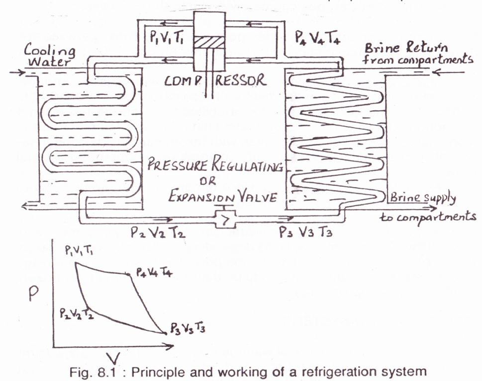
In a refrigeration system,
gas at a high pr. P¹, low vol. V¹ & high temp T¹ (35°C to 40°C) is obtained from the compressor.
It is allowed to expand slightly & cool in the condenser to a liquid at pressure P², vol. V² & SW temp T².
This cooled liquid gas is suddenly allowed to expand by passing through an expansion valve.
The expansion of the gas to vol. V³ is accompanied by a slight fall in its pressure P³ and a large fall in its temp. to T³(5°C to 25°C).
The gas is now kept in contact with the substance to be cooled.
It absorbs heat from the substance and cools it, while in turn its own temp rises to T⁴ (25° to 35°C) and pressure & volume to P⁴ & V⁴ respectively.
It is then compressed in a compressor to its pressure, volume & temperature at the first stage, i.e. P¹, V¹ & T¹.
REFRIGERATION SYSTEMS:- There are two types of refrigeration systems:
1. Direct systems:
In small refrigerated chambers on small ships and provision stores on ships.
In large installations it is difficult to monitor the pipes for leakages, wastage of expensive gas would results. Due to which a indirect system is used on large ships/compartments.
2. Indirect method and a second refrigerant:
The primary refrigerant is used to cool a tank of brine and this cooled brine is then circulated through the compartment.
Brine is chosen because of its low freezing point, 20° to 30°C, depending on its concentration and composition.
The brine is passed through separate grids surrounding the same compartment.
If one grid is blocked or chocked, the brine supply can be increased to other grids so that cooling will not be affected.
Cooling is carried out by a combination of cold brine and cool air circulation.
Precautions to be taken during the Voyage to protect cargoes which are liable to freeze:
Solidification in the cargo tanks can occur when solidifying cargoes are stowed adjacent to “cold cargoes” or cold ballast water in adjacent spaces.
Tank bottoms must therefore always be checked for hard factions especially when carrying vegetable and animal oils, at regular intervals throughout the voyage and always prior to arrival in the discharge port.
To avoid solidification of cargo in adjacent tanks, do not ballast the ballast tanks in contact with the surrounding the cargo tanks. Keep the ballast water in these ballast tanks about 30 cm below the tank top, allowing for trim.
Special care must be exercised when the vessel is advised that the shore tanks have been “squeezed” (swept) into the vessel, in such cases the “squeezed” (swept) cargo from the shore tank should as far as possible be confined to one tank onboard. The particular tank onboard which received this cargo can then be re-circulated onboard if soundings indicate a “hard bottom” problem. Solidification can also occur when inhibited cargoes or their condensates are exposed to excessive heat. If excessive heat is caused by the sun, spraying the deck area with seawater may prevent this type of solidification (polymerisation).
Because of the risk of solidifying cargo being hard and blocking the venting pipe due to evaporation through the vent pipe, the following precautions are recommended:
During voyage, regular checking of proper functioning of PV valves.
During voyage, regular checking of the vent lines by N2 / air depending on the type of cargo.
During tank cleaning, PV valves, vent lines to be thoroughly washed with hot water and same to be drained to the tank.
After the loading, all cargo lines to be flushed with high pressure N2 / air depending on the type of cargo.
General Outline of Refrigeration Systems Onboard Reefer ships:
Refrigeration process system requirements: Refrigeration is a process in which the temperature of a space or its contents is reduced to below that of their surroundings. Refrigeration is used in the carriage of some liquefied gases and bulk chemicals , in air conditioning systems, to cool bulk CO2 for fire fighting systems and to preserve perishable foodstuffs during transport of foodstuff .
Ships refrigerate cooling on plant may vary from the small domestic refrigerating unit for provisions to large plant for reefer vessels. The Chief Engineer is responsible for the correct temperatures being maintained, delegating the good operations and maintenance of the plant to the 2/E. Larger plants may have a Refrigeration Officer. Machinery under ship’s engineer responsibility may include:
Domestic ref. plant.
Cargo ref. plants
Air conditioning plants
Ventilation and heating plants
Cargo refrigerated containers
All maintenance recommendations from the makers have to be carried out regularly and according to instructions, entered in the refrigeration maintenance log, together with the test of all cut outs, i.e. HP, LP, LO, HT, that have to be carried out at regular intervals, generally one month.
All adjustment must be made according to standard good practice and records of the same entered in the log.
Filter separators and driers should be regularly cleaned in order to have always the circuit moisture, dirty and oil free. When shutting down a plant all refrigerant gas must be pumped in the liquid receiver or condenser.
Refrigeration of cargo spaces and storerooms employs a system of components to remove heat from the space being cooled. This heat is transferred to another body at a lower temperature. The cooling of air for air conditioning entails a similar process.
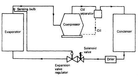
The transfer of heat takes place in a simple system: firstly, in the evaporator where the lower temperature of the refrigerant cools the body of the space being cooled; and secondly, in the condenser where the refrigerant is cooled by air or water. The usual system employed for marine refrigeration plants is the vapour compression cycle as shown in diagram here.
Fig: Vapour compression cycle
The pressure of the refrigerant gas is increased in the compressor and it thereby becomes hot. This hot, high-pressure gas is passed through into a condenser. Depending on the particular application, the refrigerant gas will be cooled either by air or water, and because it is still at a high pressure it will condense. The liquid refrigerant is then distributed through a pipe network until it reaches a control valve alongside an evaporator where the cooling is required. This regulating valve meters the flow of liquid refrigerant into the evaporator, which is at a lower pressure. Air from the cooled space or air conditioning system is passed over the evaporator and boils off the liquid refrigerant, at the same time cooling the air.
The design of the system and evaporator should be such that all the liquid refrigerant is boiled off and the gas slightly superheated before it returns to the compressor at a low pressure to be recompressed.
Thus it will be seen that heat that is transferred from the air to the evaporator is then pumped round the system until it reaches the condenser where it is transferred or rejected to the ambient air or water.
It should be noted that where an air-cooled condenser is employed in very small plants, such as provision storerooms, adequate ventilation is required to help remove the heat being rejected by the condenser. Also, in the case of water-cooled condensers, fresh water or sea water may be employed. Fresh water is usual when a central fresh-water/sea-water heat exchanger is employed for all engine room requirements. Where this is the case, because of the higher cooling-water temperature to the condenser, delivery temperatures from condensers will be higher than that on a sea water cooling system.
Temperature Records: – Temperatures of domestic refrigerated rooms have to be corrected daily by the 2nd Engineer or delegated Officer, passed to the Chief Engineer and to the Master. On larger plant suitable logs will be supplied in order to enter temperature of the cargo and all other relevant details.
Preparations & Precautions before Loading a Large Dimension Cylindrical Shaped Heavy Lift on the Deck of a Cargo Ship:
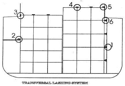
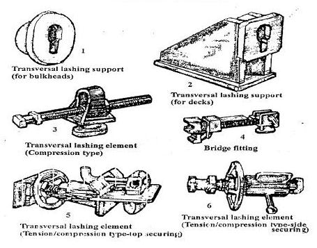
Safe stowage and securing of portable tanks:-
The provisions of Annex 2 of “Code of Safe Practice for Cargo Stowage and Securing” apply to a portable tank, which in the context of this annex, means a tank which is not permanently secured on board the vessel and has a capacity of more than 450 l and a shell fitted with external stabilizing members and items of service equipment and structural equipment necessary for the transport of liquids, solids or gases.
These provisions do not apply to tanks intended for the transport of liquids, solids or gases having a capacity of 450 l or less.
Note: The capacity for portable tanks for gases is 1,000 l or more.
General provisions for portable tanks:-
Portable tanks should be capable of being loaded and discharged without the need of removal of their structural equipment and be capable of being lifted onto and off the ship when loaded.
The applicable requirements of the International Convention for Safe Containers, 1972, as amended, should be fulfilled by any tank- container which meets the definition of a container within the terms of that Convention. Additionally, the provisions of part 6 of the IMDG Code should be met when the tank will be used for the transport of dangerous goods.
Portable tanks should not be offered for shipment in an ullage condition liable to produce an unacceptable hydraulic force due to surge within the tank.
Portable tanks for the transport of dangerous goods should be certified in accordance with the provisions of the IMDG Code by the competent approval authority or a body authorized by that authority.
Portable tank arrangements:-
The external stabilizing members of a portable tank may consist of skids or cradles and, in addition, the tank may be secured to a platform- based container. Alternatively, a tank may be fixed within a framework of ISO or non-ISO frame dimensions.
Portable tank arrangements should include fittings for lifting and securing on board.
Note: All types of the aforementioned portable tanks may be carried on multipurpose ships but need special attention for lashing and securing on board.
Cargo information:-
The master should be provided with at least the following information:
Dimensions of the portable tank and commodity if non- dangerous and, if dangerous, the information required in accordance with the IMDG Code.
the gross mass of the portable tank; and
whether the portable tank is permanently secured onto a platform-based container or in a frame and whether securing points are provided.
Stowage:-
The typical distribution of accelerations of the ship should be borne in mind in deciding whether the portable tank will be stowed on or under deck.
Tanks should be stowed in the fore-and-aft direction on or under deck.
Tanks should be stowed so that they do not extend over the ship’s side.
Tanks should be stowed so as to permit safe access for personnel in the necessary operation of the ship.
At no time should the tanks overstress the deck or hatches; the hatch covers should be so secured to the ship that tipping of the entire hatch cover is prevented.
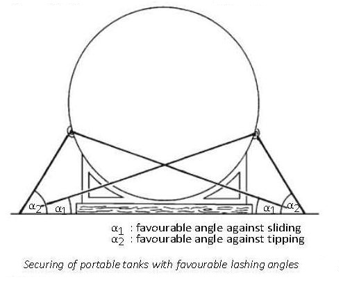
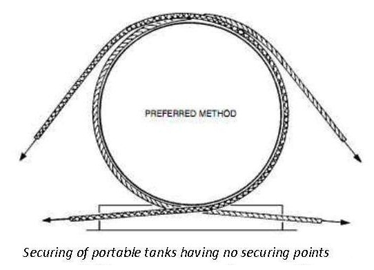
Securing against sliding and tipping:-
Non-standardized portable tanks
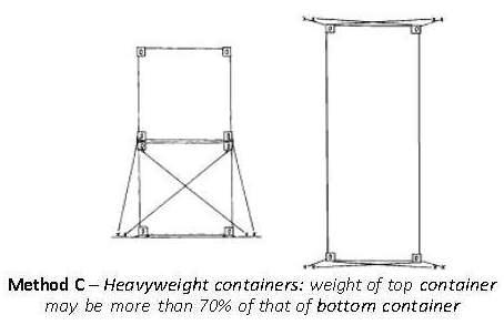
The securing devices on non-standardized p o r t a b l e tanks and on the ship should be arranged in such a way as to withstand the transverse and longitudinal forces, which may give rise to sliding and tipping. The lashing angles against sliding should not be higher than 258 and against tipping not lower than 458 to 608 (figure 3).
Whenever necessary, timber should be used between the deck surface and the bottom structure of the portable tank in order to increase friction. This does not apply to tanks on wooden units or with similar bottom material having a high coefficient of friction.
If stowage under deck is permitted, the stowage should be such that the portable nonstandardized tank can be landed directly on its place and bedding.
Securing points on the tank should be of adequate strength and clearly marked.
Note: Securing points designed for road and rail transport may not be suitable for transport by sea.
Lashings attached to tanks without securing points should pass around the tank and both ends of the lashing should be secured to the same side of the tank.
Sufficient securing devices should be arranged in such a way that each device takes its share of the load with an adequate factor of safety.
The structural strength of the deck or hatch components should be taken into consideration when tanks are carried thereon and when locating and affixing the securing devices.
Portable tanks should be secured in such a manner that no load is imposed on the tank or fittings in excess of those for which they have been designed.
Standardized portable tanks (tank-containers):- Standardized portable tanks with ISO frame dimensions should be secured according to the system of lashing with which the ship is equipped, taking into consideration the height of the tank above the deck and the ullage in the tank.
Maintenance of securing arrangements:-
The integrity of the securing arrangements should be maintained throughout the voyage.
Particular attention should be paid to the need for tight lashings, grips and clips to prevent weakening through chafing.
Lashings should be regularly checked and retightened.
Care and Maintenance of a Crane Wire:-
Wires maintenance & how to avoid mechanical damage:-
Provided that the grooves in the sheaves are in good order and that the wire is allowed to run free and not be dragged over coamings, the crane wire should not suffer mechanical damage. The Duty Officer must always be on the lookout for bad practices by crane operators, and stop any abuse of the ship’s equipment. The Chief Officer must be informed immediately if such bad practices have been witnessed in order that an appropriate claim can be made.
Standard regulations dictate that a wire must be replaced when 10% of the visible strands are broken within a length of nineteen times the diameter. This is a fair guideline and is to be the worst condition into which the wire is allowed to fall, before replacing it. Before arrival at loading/discharging ports, the wires must be checked for broken strands, by sighting along the length of the wire in both directions. It is inexcusable for any vessel to arrive in port and suffer a failure of port/inspection due to a faulty wire. This must be discovered early enough to change the wire in time to commence cargo operations without delay to the vessel, and is the responsibility of the Chief Officer.
Wires -greasing – protection:- Apart from the mechanical stresses placed on crane wires during operation, the factors most affecting their working life are:-
Weather Protection
Lubrication
Regular application of good quality wire rope grease will fulfil both purposes. It is the responsibility of the Chief Officer to ensure that sufficient stocks of suitable grease are held on board.
Because most wire greasing will be done with the jibs in the stowed position, there are certain parts of each wire which will be less accessible. These are those parts of the hoist and luff wires which lie on a sheave, and those parts which lie inside the crane structure. Attention must be paid to the ends of the wires where they are secured, as this part of the wire is often very inaccessible and overlooked. It is essential that any extra time required, is taken to ensure adequate protection in this area.
There are no circumstances which can excuse a vessel arriving in port, where the deck cranes are to be used, with the wires in a dry condition. However, it must be remembered that, especially in very warm weather, that if the crane wires have been over greased it is possible that the grease may begin to run and drop onto the cargo. This must also be avoided as it may result in cargo damage claims.
Precautions for Heavy Lift Onboard:-
Carry out a “Risk Assessment” prior to commencing the operation to ensure that all possible areas of hazard are taken account of and that all risks are at an acceptable, tolerable risk level.
Ensure that the stability of the vessel is adequate to compensate for the anticipated angle of heel that be experienced when the load at the maximum angle of outreach.
All free surface elements should be reduced or eliminated, if possible, to ensure a positive value of GM throughout the operation.
Any additional rigging, such as “preventer backstays” should be secured as per the ships rigging plan.
A full inspection of all guys, lifting tackles, blocks, shackles and wires should be conducted prior to commencing the lift by the officer-in-charge. All associated equipment should be found to be incorrect order with correct SWL shackles in position and all tackles must be seen to be overhauling.
Allowance must be made for the weight lifted plus the purchase weight.
End links ring or shackles to ride freely from whichever point they hang.
While slinging, wood or other packings to be used to protect the sling from any sharp edges on the load and to prevent the sling from cutting into the load.
Remove guard rails, if possible.
Avoid shocks due to load slipping or sudden start.
Men should be ordered to lift the gangway from the quayside and the ordered to positions of standby, to tend the vessels moorings at the fore and aft stations
The ships fenders should be rigged to prevent ship contact with the quayside at the moment of heeling.
Ensure that the deck area, where the weight is to be landed (when loading) is clear of obstructions and the deck plate is laid with timber barriers (heavy dunnage) to spread the weight of the load.
The ships plans should be consulted to ensure that the limitations of the density plan and deck load capacity is not exceeded.
Check that the winch drivers are experienced and competent and that all winches are placed into double gear to ensure slow moving operation.
Release any barges or small boats moored to the shipside before commencing any heavy lift operation.
Secure steadying lines to the load itself and to any saucer/collar connection fitment attached to the lifting hook.
Inspect and confirm the lifting points of the load are attached to the load itself and not just secured to any protective casing.
Ensure that the area is clear of all unnecessary personnel and that the winch drivers are in sight of a single controller.
Set tight all power guys, and secure the lifting strops to the hook and load respectively.
When all rigging is considered ready, the weight of the load should be taken to “float the weight clear of the quayside (loading).This vessel will cause the vessel to heel over as the full weight of the load becomes effective at the head of the derrick boom.
Some lateral drag movement must be anticipated on the load and it is important that the line of plumb is not lost with the ship heeling over.
Once the load is suspended from the derrick and the chief officer can check that the rigging of the equipment is satisfactory, then the control of the hoist operation can be passed to the hatch controlling foreman.
Assuming that all checks are in order, the chief officer would not normally intervene with the lifting operation being controlled by the hatch foreman, unless something untoward happened which would warrant intervention by the ship’s officer. This is strictly a case of too many cooks could spoil a safe loading operation.
NB: The main duties of the chief officer are to ensure that the vessel has adequate positive stability and this can be improved by filling DB water ballast tanks. Additionally, he should ensure that the derrick is rigged correctly and that all moving parts are operating in a smooth manner.
Precautions to be taken as a Chief Officer Before & During Loading of a Boiler Weighing 200 Tonnes:
A 200 ton boiler shall be categorized as a project cargo, which is defined as a cargo or equipment that may be large, heavy or out of gauge & requires specialized stowage, lifting & handling requirements, for safe shipment of such cargoes.
Precautions to be exercised while loading such project cargo are enumerated as below:
1) Such project cargoes are insured & the cargo insurers will stipulate certain conditions (a warranty) for the purpose of the insurance. If the cargo meets certain criteria then it is referred to as a critical items.
Critical items require special attention, during their loading, transportation & a careful assessment and detailed planning to carry such operation is required.
2) It is Masters responsibility to ensure that all cargo, whether it is safety stowed, properly secured & handled with care during loading & discharging operations and in accordance with the requirements of Charter Party.
The Charter Party may dictate specific responsibilities of the vessel owner, charterer and shipper, such as the specific responsibility for stowage, lashing and securing of cargo.
3) The rules of the vessel’s classification society, will also set out the requirements for maintenances of vessels, including equipment required for loading, stowage & securing of project cargoes. If these requirements are not followed, the vessels owners may be liable in the event of an incident.
4) The vessel’s Cargo Securing Manual guidelines should be referred to ensure the vessel suitability to carry such project cargo & securing arrangements for the same.
5) The Code of Safe Stowage CSS Code, 2003. should be referred in conjunction with the Cargo Securing Manual for safe stowage and securing recommended for a range of cargoes including project cargo.
6) The Intact Stability Criteria is specified in Res. A. 749 (18) should be confirmed by the Master, sufficient to permit & safe margin of positive stability throughout the loading operation & voyage.
Damaged stability criteria as set out in SOLAS Chp. II-I (MSC Circ.82) also need to be considered.
7) The shipper shall provide instructions for the safe and proper stowage and securing of the cargo. For more complicated shipments, particularly those for large heavy items a detailed “Transport Manual” or “Method of statement” should be provided which include:
Management of project, responsibilities & key contacts.
Details of cargo/ vessel.
Vessel strength & stability requirements.
Port details.
Loading procedure.
Stowage Requirements
Voyage Planning & transshipment
Discharge Procedures
8) A Marine Warranty Surveyor is appointed on behalf of the cargo insurance under writers who insures the shipment of cargo. In cases, where a warranty surveyor attends to approve loading & securing of cargo, a certificate approval (COA) or Letter of Approval is to be issued on satisfactory completion of operations, adhering to the standards of safe stowage & securing.
Definition of Lifting Appliances with context of ILO- 152 convention, 1979:-
The term Lifting Appliance covers all stationary or mobile cargo-handling appliances, including shore-based power-operated ramps, used on shore or on board ship for suspending, raising or lowering loads or moving them from one position to another while suspended or supported.
A Bill of Lading, abbreviated as B/L is a document issued by a carrier (or an agent, acting on behalf of the ship owner) to acknowledge receipt of a shipment of cargo.
Under the terms of many carter parties and some voyage charter parties, the owner transfer the authority to sign the BL’s to the charterers or charterer’s delegated agent thereof, thereby acting as an agent of the ship-owner.
Master should confirm with the Charter party agreement in understanding who is authorised to sign the BL. If doubt exists, he should clarify the specific instructions from the owners & time charterers.
If the charter’s agents is authorised to sign the BL on behalf of Master then the Master should issue a Letter of authorization to the Charterer’s agent. The wordings of such authorization often dictated by the owner’s or chaterer’s voyage instruction.
A bill of lading is a negotiable document and serves three main functions:-
It is a conclusive receipt i.e. an acknowledgement that the goods have been loaded.
It contains or evidences, the terms of contract of carriage entered between the “carrier” & the “shipper” in order to carry out the transportation of cargo as per sales contract entered between buyer & seller.
It serves as document of title to the goods.
(Please Note:- The contract terms evidence by a bill of lading are usually governed by the Hague Rules, the Hague-Visby Rules or the Hamburg Rules).
Types of Bill of Ladings:
Straight Bill of Lading:- When a B/L is issued in original(s) to a named “cosignee”, it is termed as “Straight Bill of Lading”, which is a “Non-negotiable and non-transferable document.
Seaway B/L / Express Release:- When a B/L is issued to a “named cosignee” but without any originals, it may be considered to secure B/L. This B/L is also non-negotiable and non-transferrable document.
A Seaway Bill is issued:-
Where the Shipment takes place between two different companies but there are no negotiation required between the two, via a Bank for relase of cargo and also,
The shipper does not need to submit original B/L to procure his payment.
Negotiable or Order B/L:- When a B/L is issued in originals and cosigned to “to order” or “to order of shipper” it is termed as negotiable B/L or Order B/L.
Before signing Bill of Lading the Master must ensure that:-
The goods are actually aboard and the Bill of Lading is correctly dated.
Please Note:- The B/L date must be date of completion of loading and not pre/past dated. Any issues arising thereby consult the owners and/ or comment operators.
The description of goods complies with the mate’s receipt, failing which the bill of lading should be claused accordingly:
If cargo “quantity” or “quality” discrepancies exists, insist that remarks are placed on “Mate’s Receipt” and the same reflected on the original B/L’s.
If resisted by the agent to accept a claused B/L, the Master must issue a letter of protest, specifying the cargo quantities as per shore scale, ship’s draught survey quantity & attending surveyor’s quantities and cargo figure difference. Do not issue letter or Authorisation to the charterer’s agent and inform owners & time charterer’s accordingly.
The Master should only sign the same number of original B/L’s as indicated on the face of the B/L.
If original B/L to be carried onboard, inform owners and/or commercial operator advising on the no. of originals to be signed and retained onboard.
Check B/L format, especially for Frieght Clause. If “Frieight Prepaid” is written, immediately inform owners and/or commercial operators and seek instructions.
If any cargo is shipped on deck, inform owners and/or commercial operators and time charterer and clause the B/L accordingly. “Carried on Deck, solely at Shipper’s Risk & Responsibility, carrier not responsible for loss or damage how so ever caused”.
If the sufficient cargo is not supplied as per stowage plan and your cargo demand as indicated also in the N.O.R. the vessel must issue “Deadfreight Letter” and notify shippers charter’s and owner and the same to be annexed to the B/L.
At the discharge port, the Masters authorises the release of cargo to co-signee or their agent, when presented with original B/L, duly endorsed by the cosignee or their agent.
Only owners and/or commercial operators can authorise in writing to Master to release cargo W/O original B/L, while procuring a LOI charter’s to do so.
After receiving original B/L at discharge port, ensure it is remarked “Accomplished” i.e. B/L is cancelled upon delivery of cargo to its owner.
Send copy of B/L immediately to the owner’s and Charterer’s advising its receipt and that you are releasing the cargo to the consignee.
Actions to be taken while Observing damage cargo during discharging operation on board Car Carrier ships:
Stop discharge, take as many photo as possible from different angle showing the damage.
Inform Master. Describe how the damage took place.
Take the sign of the foreman on the stevedore damage form.
Take printouts of the photo and attach it to the stevedore damage form.
If stevedore not signing the damage report form raise LOP. Inform central planner in containers. (Safeguard the owner’s interest.)
General Precautions to be observed while working Ro-Ro include:
Preventing unauthorised entry of vehicles and pedestrians into the terminal.
Enforcement of speed limits.
Segregation of vehicles and pedestrians.
Adequate marshaling of passenger carrying vehicles.
Provision of safe routes from car decks to passenger accommodation.
Maintain clear approach to Ro-Ro ramp.
Only those involved in loading/ unloading allowed onto ramp.
If pedestrian access must be via the ramp, provide safe means of access e.g. raised walkway.
Ramp kept clear of obstacles.
Good co-ordination between ship/shore to maintain ramp at safe level/gradient.
Clear rules controlling movement of vehicles on/off the ship.
Procedures for abnormal loads
Lashing Teams:-
Wear Protective clothing.
Work in teams or in sight of each other.
Stand where visible to loading vehicles.
Use whistle stop and clear, standardised hand signals
Trained and competent in lashing procedures.
Clear safety procedures for using ships cargo lifts.
Safe systems of work for Sto-Ro especially regarding safe use of large lift trucks.
Control Vehicle fume:
Ensure ships fans running before loading / unloading begins.
Minimise number of engines running at one time.
Maintain company controlled vehicles in accordance with manufacturers guidelines.
Pre-loading precautions for Loading Cars on a Car Carrier:
Preventing unauthorized entry of vehicles and pedestrians into the terminal.
Enforcement of speed limits.
Segregation of vehicles and pedestrians.
Adequate marshalling of passenger carrying vehicles.
Provisions of safe route from car decks to passenger accommodation.
Maintain clear approach to Ro-Ro ramp.
Only those involved in loading/ unloading allowed onto ramp.
If pedestrian access must be via the ramp, provide safe means of access e.g. raised walkway.
Ramp kept clear of obstacles.
Good co-ordination between ship/shore to maintain ramp at safe level/ gradient.
Clear rules controlling movement of vehicles on/off the ship.
Procedures for abnormal loads.
Lashing teams
Wear protective clothing.
Work in team or in sight of each other
Stand where visible to loading vehicles
Use whistle stop and clear, standardized hand signals
Trained and competent in lashing procedures.
Clear safety procedures for using ships cargo lifts.
Safe systems of work for Sto-Ro especially regarding safe use of large lift trucks.
Control vehicle fume
Ensure ships fans are running before loading/ unloading begins.
Minimize number of engines running at one time.
Maintain company controlled vehicles in accordance with manufacturer’s guidelines.
Safe method of stowage of heavy cargo items such as locomotives and project cargo being brought by your ship during monsoon:
“ANNEX 5 of CSS code – Safe stowage and securing of heavy cargo items such as locomotives, transformers, etc.”
Following are guidelines wrt lashing of heavy cargoes:
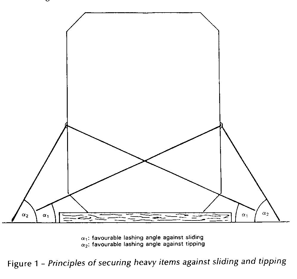
Securing Against Sliding and Tipping:
Whenever possible, timber should be used between the stowage surface and the bottom of the unit in order to increase friction. This does not apply to items on wooden cradles or on rubber tyres or with similar bottom material having a high coefficient of friction.
The securing devices should be arranged in a way to withstand transverse and longitudinal forces which may give rise to sliding or tipping.
The optimum lashing angle against sliding is about 25°, while the optimum lashing angle against tipping is generally found between 45° and 60° (fig 1).
If a heavy cargo item has been dragged into position on greased skid boards or other means to reduce friction, the number of lashings used to prevent sliding should be increased accordingly.
If, owing to circumstances, lashings can be set at large angles only, sliding must be prevented by timber shoring, welded fittings or other appropriate means. Any welding should be carried out in accordance with accepted hot work procedures.
Securing Against Heavy Seas on Deck:-
Whilst it is recognised that securing cargo items against heavy seas on deck is difficult, all efforts should be made to secure such items and their supports to withstand such impact and special means of securing may have to be considered.
Heavy Cargo Items Projecting over the Ship’s Side:-
Items projecting over the ship’s side should be additionally secured by lashings acting in longitudinal and vertical directions.
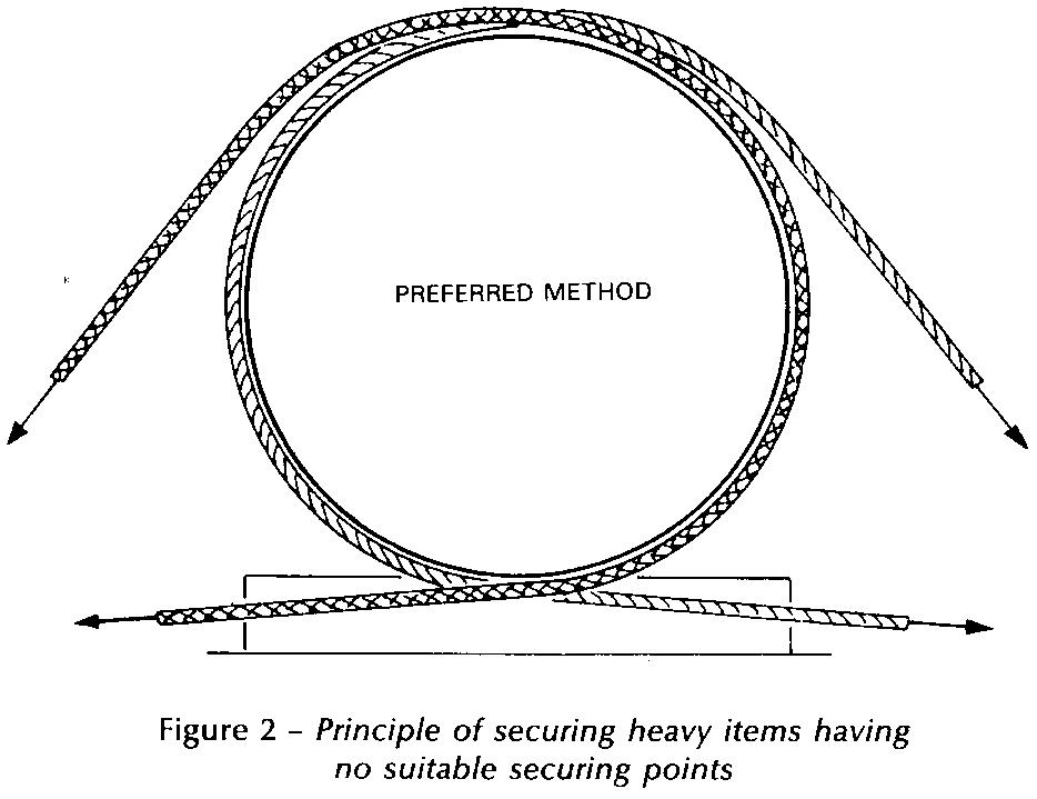
Attachment of Lashings to Heavy Cargo Items:-
If lashings are to be attached to securing points on the item, these securing points should be of adequate strength and clearly marked. It should be borne in mind that securing points designed for road or rail transport may not be suitable for securing the items on board ship.
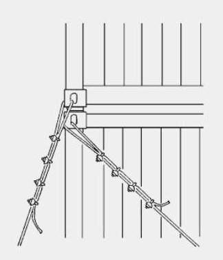
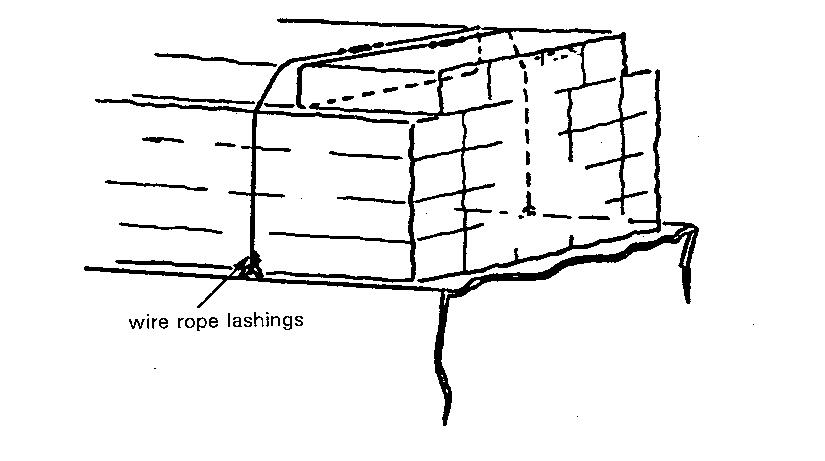
Lashings attached to items without securing points should pass around the item, or a rigid part thereof, and both ends of the lashing should be secured to the same side of the unit (figure 2).
Securing devices should be assembled so that each component is of equal strength.
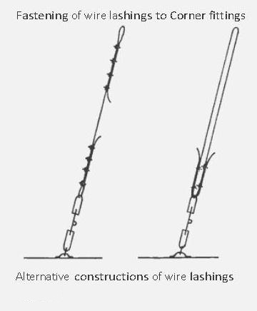
Particular attention should be paid to the correct use of wire, grips and clips. The saddle portion of the clip should be applied to the live load segment and the U-bolt to the dead or shortened end segment.
Mixed securing arrangements of devices with different strength and elongation characteristics should be avoided.
Planning & Preparations to be done before Loading and Unloading of Vehicles on a Car Carrier:
Stowage:
Shipper’s special advice or guidelines regarding handling and stowage of individual vehicles should be observed.
Vehicles should as far as it is possible, be aligned in a fore and aft direction. Athwartship stowage should only be allowed with the express permission of the Master having taken into account the anticipated weather for the intended voyage and provided that adequate securing arrangements can be made.
Vehicles should not be stowed across water spray fire curtains or flood barrier doors where fitted.
Vehicles should be closely stowed athwartships so that, in the event of any failure in the securing arrangements or from any other cause, the transverse movement is restricted. However, sufficient distance should be provided between vehicles to permit safe access for the crew and for passengers getting into and out of vehicles and going to and from accesses serving vehicle spaces.
Safe means of access to securing arrangements, safety equipment, and operational controls should be provided and properly maintained. Stairways and escape routes from spaces below the vehicles decks should be kept clear.
Vehicles should not obstruct the operating controls of bow and stern doors, entrances to accommodation spaces, ladders, stairways, companionways, escapes, access hatches, firefighting equipment, controls to deck scupper valves and controls to fire dampers in ventilation trunk.
Parking brakes, where provided, of each element of a combination of vehicles should be applied.
Semi-trailers should not be supported on their landing legs during sea transport unless the landing legs are specially designed for that purpose and so marked.
Semi-trailers should not be supported on their landing legs during sea transportation unless the deck plating has adequate strength for the point loadings, or there are suitable arrangements to spread the load.
Uncoupled semi-trailers should be supported by trestles or similar devices placed in the immediate area of the drawplates so that the connection of the fifth-wheel to the kingpin is not restricted. Such trestles or devices should be tested and clearly marked to show their maximum permitted load which must not be exceeded.
Depending on the area of operation, the predominant weather conditions and the characteristics of the ship, freight vehicles should be stowed so that the chasses are kept as static as possible by not allowing free play in the suspension. This can be done by securing the vehicle to the deck as tightly as the lashing tensioning device will permit or by jacking up the freight vehicle chasses prior to securing.
Depending on the area of operation, the predominant weather conditions and the characteristics of the ship, freight vehicles should be stowed so that the chassis are kept as static as possible by not allowing free play in the suspension. This can be done by securing the vehicle to the deck as tightly as the lashing tensioning device will permit or by jacking up the freight vehicle chassis prior to securing. Since compressed air suspension systems may lose air, adequate arrangements should be made to prevent the slackening off of lashings as a result of air leakage during the voyage. Such arrangements may include the jacking up of the vehicle or the release of air from the suspension system where this facility is provided.
Securing:
Securing operations should be completed before the ship leaves the berth.
Persons appointed to carry out the task of securing vehicles should be trained in the use of the equipment to be used and in the most effective methods for securing different types of vehicles.
Persons supervising the securing of vehicles should be conversant with the contents of the “Cargo Securing Manual”.
There should be an adequate supply of cargo securing gear which is maintained in a sound working condition.
Freight vehicles of more than 3.5 tonnes should be secured in all circumstances where the expected conditions for the intended voyage are such that movement of the vehicles relative to the ship could be expected. So far as is reasonably practicable the securing arrangements should be adequate to ensure that there will be no movement from any cause which will endanger the ship.
When freight vehicles are being stowed on an inclined deck, the wheels should be chocked before lashing commences. During discharge, sufficient restraints should remain in place until the tractor unit has been connected, where appropriate.
Lashings should not be attached to or led across lamp brackets, trailer landing legs, kingpins, sideguards or bumpers except those specially designed for this purpose.
When wheel chocks are used to restrain a semi-trailer they should remain in place until the semi-trailer is properly secured to the semi-trailer towing vehicle.
To avoid being damaged during loading and unloading all securing equipment should be kept clear of moving vehicles on the vehicle deck.
Inspection routines for securing equipment should be specified in the Cargo Securing Manual and require at least one inspection every six months by a trained person. Defective equipment should be taken out of service and placed where it cannot be used inadvertently.
Lashing Arrangements:
Lashings should have strength and elongation characteristics appropriate for the mass of vehicle being secured.
Steel chains are commonly used for lashing freight vehicles of more than 3.5 tonnes gross vehicle mass (GVM). Webbing straps or other novel securing systems may be used instead of steel chain, provided that they have an equivalent strength and suitable elongation characteristics (see IMO MSC/Circ 812 for further details).
Chains/straps and associated elements (eg Hooks, shackles, elephant’s feet and tensioning devices) should have an MSL of 100 kN.
Where, exceptionally, wire ropes or other materials are used their breaking load should be atleast 200 kN.
Hooks and other devices which are used for attaching a lashing to a securing point should be designed and applied in a manner which prevents them from disengaging from the aperture of the securing point if the lashing slackens during a voyage.
Lashings should be so designed and attached that, provided that there is safe access, it is possible to tighten them if they become slack.
Securing points provided on vehicles should only be used for lashing the vehicle to the ship. Only one lashing should be attached to any one aperture loop or lashing ring at each securing point.
The lashings are most effective on a vehicle when they make an angle with the deck of between 30 and 6 degrees. When these optimum angles cannot be achieved, additional lashings may be required.
Where practicable, the arrangement of lashings on both sides of a vehicle should be the same, and angled to provide some fore and aft restraint with an equal number pulling forward as are pulling aft.
Crossed lashings should, where practicable, not be used for securing freight vehicles because this disposition provides no restraint against tipping over at moderate angles of roll of the ship. With these vehicles, lashings should pass from a securing point on the vehicle to a deck securing point adjacent to the same side of the vehicle. Where there is a concern about the possibility of low coefficients of friction on vehicles such as solid wheeled trailers, additional cross lashings may be used to restrain sliding.
Bearing in mind the characteristics of the ship, the approved “Cargo Securing Manual” and the conditions expected on the intended voyage, the master should decide on the number of lashings, if any to be used on each class of vehicle having regard to any vehicles which by the nature or disposition of their load may require particular attention.
Enclosed spaces are a fundamental component to the ship’s structure and are also circuitously critical for the economics of running the shipping company. A large part of the ship’s earnings in the form of cargo (dry as well as wet) is exhumed from large void spaces commonly known as ‘tanks’, within the ships configuration. As a matter of fact, the steel tanks aid with the ship’s stability, especially when stability is associated to juggling between filling and discharge of fuel oil or water as ballast / domestic.
Considering the immense significance of these spaces, they have to be regularly maintained. Planned inspections and regular cleaning / repairs would be best for ascertaining top shape of the ship’s hull and its components.
However, it is proven that over time the ships’ steel deteriorates structurally, and if left unchecked, can worsen to serious framing and compositional defects with sometimes causing loss to ship, even lives. Consequently, in order to avoid such premature loss to life or for that matter loss of revenue from forced off-hire periods, effective repairs are indispensable; this includes visibly examining the tanks methodically.
The intention of this study is to present a generic guide of how to go about inspecting the ships tanks namely, cargo holds / tanks (dry and wet), ballast tanks, void spaces, fuel oil tanks, fresh water storage tanks, etc.
Let’s first quickly run down through the general defects that affect the steel structures due to direct wear and tear.
1. Corrosion – Also considered as ‘material wastage’, it is the lead cause for structural deformations and fracturing. It is by far the most ‘popular’ of all other defects directly related to steel and its components. If left unattended, corrosion is a disaster waiting to happen; either by cargo or fuel oil contamination, structural losses, pollution and finally possible loss of the ship itself.
2. Deformation – It is a sub-component defect caused due to damage of steel platings or material failure. It could be a change in shape or physical disfigurement of steel that is caused either by implosion (caused due to vacuum build up in tanks) or explosion, excessive dynamic (wave bending / loading) as well as static stress (ship’s hogging and sagging conditions)and strains onto the steel structures, and likewise. It should be noted that deformations observed on the ship’s hull are more likely to affect structures on the interior too.
3. Fractures – This is due to propagation of cracks through the steel plating, which have been left unattended, obviously. Most of it occurs due to excessive stress concentrated on weakened steel plates throughout the tanks’ dimensions. There have been many cases where inspectors have arrested ships, especially bulk carriers, where imminent cracks (mainly due to concentration of stress) through the cargo areas have been observed. Welding defects have also been observed to be the cause of fractures.
As we are aware that entering the tank or the enclosed spaces onboard encompasses certain mandatory procedures, which should be followed in particular. Prerequisites such as Permit to Work in Enclosed Spaces, PPE, high beam lighting, oxygen / gas detection meters, communications, etc. are mandatory while undertaking such critical operations. Once all the essentials are in place, a competent officer should head the inspection process after chalking out the tasks that are required to be ticked off, say for completing a PMS. Needless to say, onboard checklists provide a complete synopsis as to what one has to confirm while inspecting the tanks.
Here are a few pointers one should specifically identify while inspecting the steel tanks:-
1. Assessing the overall condition – Immediately on entering the enclosed space one can figure out the tank’s well being by considering the state of the access ways and the ladders, paint coatings, and by closely observing areas susceptible to corrosion such as near the weld joints. Rungs, step ways and ladders are often the foremost members that are exposed to deterioration due to oxidation. The competent officer should examine the material wastage throughout the set of access ways and related components. An overall study of the paint coating would permit the competent person to estimate how the tank has reacted to general corrosion. For easy identification of loop holes, the paint applied on the surface is generally light in colour. Thereby, re-coated areas can be easily spotted, should be re-checked for coating failure or for scaling or pitting in the vicinity.
2. Condition of corrosion levels – General corrosion appears to be as a non-protected oxidation that tends to crop up homogeneously on internal surfaces of the holds or tanks which have been left uncoated. The corroded scale frequently breaks off, revealing the bare metal, which is susceptible to corrosive attack. In tanks and holds that have been coated, corrosion starts affecting the moment the coating starts breaking down. Determining thickness reduction in the steel plates is difficult unless excessive shrinking has occurred.
For example, corrosion on the inner surfaces of the liquid cargo tanks (example, Crude Oil Tankers) is mainly due to the mixture of corrosive gases, crude oil acids, as well as sea water (Crude oil washing). This along with the fluctuations in temperatures within the tanks and structural flexing, over a period of time, shrinks the thickness of the steel plating and associated supports, ultimately leading to failure of the steel structure.
Careful examination should be carried out in areas such as – in the vicinity of sounding pipes and striker plates, openings for the air vents and tank gauging, internal piping including expansion joints, dresser coupling and related fittings / joints / clamps, near the operational valves within the tanks, bilges and tank top areas, underside of hatch coamings / tank openings, bulkheads in general, joints associated with girders, web frames, etc.
3. Condition of ‘sacrificial’ anodes fitted inside the tank – Normally such anodes are made up of zinc among other elements and provide excellent preventive measures to fight corrosion within the tanks, especially the ballast tanks. Due to their sacrificial nature, the anodes, over a period of time get ‘wasted’. Hence, in order to maintain their integrity, anodes have to be checked and inspected closely for excessive wear and tear. A record of material wastage should be maintained for future examining. One must also inspect whether the anodes are well secured to the brackets provided.
4. Checking for Damages / Cracks / Deformations – Adequate lighting in the tanks is necessary for the inspection work and for identifying deformations or surface dents. Shadows are one of the best indicators to highlight any buckling or cracks within the tanks. However this may not be the case for darker paint coatings (Coal Tar Epoxy, for example) where the tanks have to be lit up to the max in order to locate the defects. Deformations may generally not be readily obvious when viewed over a larger area. To identify this, it is good idea to highlight the area using a high beam torch by projecting it parallel to the surface. Where it is difficult to identify defects in a straight line by the torch, the old school method of using a length of string or rope could be considered for determining the obscured deformations on the surfaces.
Buckling is another condition of large deformations which can be caused due to a diminutive increase in loads. Permanent buckling may arise due to overloading weak structures (read – corrosion or contact damage)
5. Pitting corrosion and blister formation– Pitting Corrosion is often known to be observed in the bottom plating of ballast tanks especially near the ‘bell-mouth’, near the ‘bell-mouth’ in a liquid cargo tank, or next to suction wells associated with the submerged pumps fitted within the tanks. Pitting Corrosion begins mostly with the local breakdown of the coatings, exposing the bare metal, and thereby getting accentuated by oxidation and galvanic reactions in the area.
Blister formation is a common site in areas where the surface preparation is inadequate prior to application of paint coats or for some reason the coating failed to adhere to the surface. The officer must be on a look out for these unwary bumps on the tank surfaces that may act as alibi to the mounting decay underneath.
6. Condition of the tank gauging systems – Gauging systems that include gas measuring gauges, pressure gauges, temperature gauges, remote level sensing meters, sounding pipes as well as the striker plates should be checked for operational abnormalities. Rusting, too, is often found underneath the tank top near the conduits that encompass the gauges. If possible, it is always a good idea to try and clear out debris (example – mud, oil deposits) manually from the remote measuring sensors and attempt operating them. For example, during the inspection process physically testing the ‘remote’ gas measuring devices may be well worth the assessment.
The gauges fitted inside or outside the tank must be calibrated during major inspection (dry dock) or at intervals defined by the maker.
Ro-Ro Ship – Condition of the tank gauging systems
7. Condition of the Safety Devices – Safety devices fitted in the tanks are critical for providing the operators a remote indication of an unwanted threat such as water ingress in the bilges of cargo holds due to sweating or any other reason for that matter. The importance of such devices onboard is high and should be regarded as priority for visible examination. It is not very frequent that the bilge high level and low level alarms of critical spaces such as in the ship’s chain locker, dry cargo holds, void spaces, etc. would be manually tested and scrutinised closely for operational deficiencies.
8. Condition of Mud or Sludge Build Up – Accumulation of mud and oily sludge in the tanks could be detrimental in terms of hiding away serious defects and also to promote development of structural deterioration underneath the horizontal / parallel surfaces. Therefore, it is highly recommended to remove the excess debris prior any tank inspection, this means washing the crude oil tanks enough in order to visibly locate the defects, or physically hosing down the mud accretion in ballast tanks. This also aids in identifying any bottom shell pitting corrosion or deformations.
9. Condition of Cargo Equipment – Cargo equipment within the tanks include heating coils, cargo pumps, crude oil washing machines, remote gauging systems, temperature / heat sensors, etc. Leak test using compressed air or steam could be carried out on heating coils whereby the pipe-work and steam traps within the tanks must be thoroughly inspected visually for faults and leaks. The competent officer should also physically ensure the optimal operation of all the cargo equipment fitted internally. This could be done by remotely trying out the system from a control room and feedback confirmed from within the tank. Any irregularity in the equipments’ operation must be recorded and later reported.
Finally, a few other areas onboard susceptible to defects and damages that must be frequently examined –
– Ballast tanks that are bordering the hot Engine Room spaces
– Ballast and void tanks neighboring the heated fuel oil and cargo tanks
– Tanks that are in the vicinity to areas where vibration levels are high
– Side shell spaces between the loaded and light draughts
– Tanks adjacent to external tug contact points
– Spaces in the forward part of the vessel, especially to be considered after heavy weather
Therefore, in order to detect and identify where a fault has occurred in the enclosed space most of the above mentioned factors would be needed to take into consideration. For evidence and record keeping, using an intrinsically safe camera or any camera with a certified explosion proof housing for that matter is highly recommended.
Need to monitor Atmosphere in Ro-Ro Spaces:-
When internal combustion engines exhaust into a hold, intermediate deck, or any other compartment, the employer must ensure that the atmosphere is tested as frequently as needed to prevent carbon monoxide (CO) concentrations from exceeding allowable limits.
These tests must be made in the area in which workers are working by persons competent in the use of the test equipment and procedures.
Employers should ensure that workers control loose paper within RO-RO areas.
Papers can be sucked into the ventilation system, blocking airflow and allowing the buildup of harmful gases.
Employers should closely monitor air quality during all operations where overexposure may occur.
Most modern car carriers have efficient exhaust ventilation systems. Ventilation systems in cargo holds should be started 15 minutes prior to starting work.
The time needed may vary depending on the size of the hold and the airflow.
Vehicle Stowage and Securing (Ro-Ro Ships & Car Carrier):
IMO Resolution A. 489 (XII) – Safe Stowage and Securing of Cargo Units and other entities in Ships other than Cellular Container Ships. (Guidelines for Cargo Securing Manual).
IMO Resolution A. 533 (13) – Elements to be taken into account when considering the same stowage and securing of cargo units and vehicles on ships.
IMO Resolution A. 581 (14) – Guidelines for securing arrangements for the transport of road vehicles on ships.
IMO Resolution A. 489 (XII) – Code for safe practice of cargo stowage and securing. Annex 4 – Safe Stowage and securing of wheel-based cargoes.
A stable vehicle deck needs to be maintained, so all Ro-Ro ferries are built with stabilizers of some form. However, cargo movement can still expect to occur in very rough sea conditions even when stabilization systems are operational. To prevent movement at sea individual vehicles are secured.
The stowage / securing of vehicles should be supervised by a responsible Ship’s Officer assisted by at least one other competent person.
Vehicles must be loaded, stowed and secured in accord with the Cargo Securing Manual (CSM) (IMO Res. A. 489 (XII)), as approved by the authority.
Lashing material used should have sufficient strength and should comply with the CSM.
Securing points shall be provided on ship’s deck, spaced not more than 2.5m in the F & A direction and in the arthwartship direction not less than 2.8m and not more than 3m, same should be mentioned in the CSM of the ship.
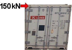
Minimum strength of securing point on deck should be 120kN and if more than one lashing can be attached than – no. of lashing x 120kN.
In Ro-Ro ships the spacing and the strength may vary depending on the special consider which may be required to stow and secure road vehicles.
Securing points on road vehicles shall be provided which shall be capable of accepting only one lasing, highlighted, provided effective restraints to the vehicle by the lashing and should be of adequate strength.
Vehicles which are not provided with securing points should have those places clearly marked, where lashing may be applied.
Cargo spaces in which wheel based cargo is to be stowed should be dry, clean and free from grease and oil.
Vehicles should as far as possible be aligned F & A, with sufficient distance between vehicles so as to allow access through the vehicle deck.
The parking brake on each vehicle/ unit should be applied and where possible the unit should be placed in ’gear’.
Where drop loads or uncoupled units are being carried these should be landed on trestles or equivalent support, prior to being secured by chain or other suitable securing constraint.
Road vehicles should be stowed so that the chassis are kept as static as possible, by not allowing free play in the suspension of the vehicles. By either compressing the springs by tightly securing the vehicle to the deck, by jacking up the chassis prior securing the vehicle or by releasing the air pressure on the compressed air suspension system.
Wheels of vehicles stowed on decks should be ‘chocked’ and the hand brakes to be applied.
Cargoes stowed on wheel based units should be adequately secured to stowage platforms or where provided with suitable means, toits sides. Any movable external components attached to a wheel based unit, such as derricks, arms should be adequately locked or secured in position.
Suitable lashings against the incline should be secured and the unit left in an opposing gear.
Vehicles should be lashed using the correct securing points provided on the vehicle and deck.
All lashings applied whether of a ‘hook’ type or other variety should be secured in such a manner that in the event of them becoming slack, they are prevented from becoming detached and should also permit tensioning during the voyage when they become slack.
All vehicle / cargo units should be secured prior to the vessel leaving the berth and such securings should be at the master’s discretion to be most effective.
While enroute these lashings should be regularly inspected to ensure they remain effective during the time at sea.
Personnel engaged on vehicle deck inspections should take extreme caution against injury from swaying vehicles.
If necessary the master may alter the ship’s course while such inspections are ongoing to reduce the motion on the vehicle deck.
Lashings should only be released once the ship is secured at the berth and personnel so engaged should take care when clearing securings which may be under tension.
Note: Lashings are considered most effective at between 30deg and 60deg to the deck line. Alternatively, additional lashings may be required.
Unit Securing – chain lashings:
Ro-Ro units are secured in accordance with the ‘Cargo Securing Manual’. In some short sea voyages, during the summer season and with a predominately good weather forecast, units may not even be secured other than hand brakes and left in gear.
However, at the Master’s discretion, chain lashings could be applied by the crew if and when circumstances dictate that securing becomes necessary.
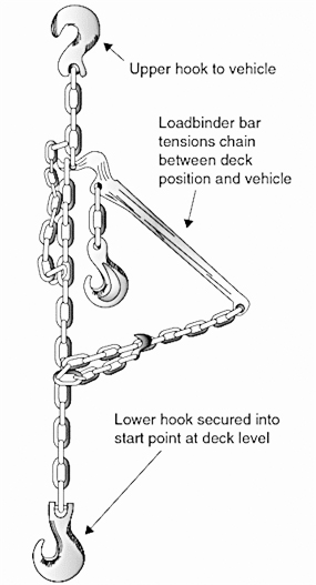
In virtually all cases, hazardous units would automatically be chained down. Chain lashings vary but can be applied between a deck star lashing point and the unit itself, then tensioned by al load-binding lever.
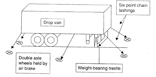
Such lashings can be secured and tensioned quickly and lend to labour saving. The number of lashings per unit will be variable, depending on the weight and size of the vehicle. However, a standard 40-ft unit would usually be fitted with a minimum of 6 lashings.
Ro-Ro Ship – Drop Unit Stowage
Drop Unit Stowage
Example of Chain Lashing
Example of Chain Lashing
Vehicles are built with star lashing points or ‘elephant feet’ type anchor points. Lashings have club foot fitting into these points, with a hook at the opposite end. Alternately, hooks are used at each end.
Procedures for Opening, Closing and Securing of hull openings on Ro-Ro Ships:
The documentation must enable the user to operate the shell doors, inner doors and ramps, if applicable, in a safe manner. The closing and securing functions need to be described particularly clear. Besides safety precautions also the maneuvers running automatically must be explained in detail in order to provide a full understanding of the functions.
References shall be given for troubleshooting of faults and failures and measures to be taken consequently. Emergency stops and emergency operation e.g. in case of energy supply loss shall be described.
The documentation on the operating procedures is to be posted on board at appropriate places.
Problem areas of Ro-Ro vessels:
The Problem of Stability: – If a vessel maintains its stability at sea then it is safer to sail. However, the problem with the RO-RO ship is its design, which includes cargo in upper decks and accommodation at even higher levels. Even a minor shift of cargo in the ro-ro vessel can become a major threat to the stability of the ship. Similarly, hull failure leading to flooding can result in capsize of the vessel in no time. The effects of wind and bad weather on high accommodation can also disturb the ship’s stability.
High Freeboard: – In Ro-Ro ships which carry only cargo, the general arrangement of cargo access door is close to the water line. In the event of listing, the door can get submerged leading to high chances for ingress of water inside the ship which will lead to capsize.
Cargo Access Door: – As discussed above the effect of listing of the ship leads to ingress of water if the cargo doors are open or damaged. One weak point of ro-ro vessel is that sometimes the cargo door itself is used as a ramp which makes the ship more vulnerable to damages.
Lack of Bulkheads: – The subdivision of ro-ro ship from inside lacks from the transverse bulkheads, leading to lower water tight integrity when water ingress or flooding takes place. Lack of bulkhead also leads to spreading of fire more quickly as no subdivision is present to contain the fire.
Location of Life Saving Appliances (LSA):- When a ship is to be abandoned, life raft and lifeboats are used to leave the ship as soon as possible. The location of lifeboat and life rafts on ro-ro ships is usually very high, which makes it even difficult to lower them at sea especially when the ship is listing.
Weather condition: – Another reason which acts externally on the Ro-Ro vessel is the rough weather, which may result in reduction in the stability and cause heavy rolling of the ship. Heavy rolling has lead to capsizing of ships in the past.
Cargo stowage: – Cargo stowage is very important operation on Ro-Ro vessel for any loose cargo (trailer, cars etc.) can give rise to a chain reaction leading to heavy shift in cargo position. The trucks and trawlers loaded on board also carry cargo inside them and any shift of that cargo can also lead to listing of the ship.
Cargo Loading: – It is very difficult to have a sequential loading of cargo as cargo arrives on terminals at different intervals and due to lack of time on port. This further leads to uneven cargo distribution, something for which nothing can be done about. Lack of proper cargo distribution has been the reason for several ship accidents in the past.
A cellular vessel is a container ship specially designed for the efficient storage of freight containers one on top of other with vertical bracings at the four corners. The majority of vessels operated by maritime carriers are fully cellular ships.
Before 1991 most containerships where constructed with hatch covers. Because of the longer load and unloading times of these types of ships the cellular type was invented. As loading and unloading occurs only vertically and the containers have standardized dimensions (TEU), large quantities of cargo can quickly be loaded using gantry cranes.
Advantages:
The cargo handling is more efficient resulting in shorter time in port
Guide rails hold the containers into place instead of time consuming lashings
No need of hatch covers, reducing maintenance, weight, and handling
There is a high freeboard resulting in a stronger construction
Containers lashed to cellular vessels are less vulnerable to crew tampering than containers on mixed-use cargo vessels, making them less of a risk from the standpoint of port security.
Disadvantages:
The high freeboard results in higher registered tonnage.
The price of the ship is high due to the amount of steel used and the complex design process.
The absence of hatch covers means that rain water and overcoming seawater can freely enter into the cargo hold. Therefore, higher requirements of bilge systems are applicable to open cargo holds.
Bay Plan of a Cellular Container Vessel:
Bay plan of a Cellular Container Vessel
Information provided in Bay Plan of a Container System:-
Each slot for a container is given a number which indicates its position on ship. The number consists of six digits the front “two digits” indicate the bay, the second “two digits” indicate the row and last “two Digits” indicate the tier.
Bays – Numbered from fwd to aft. In 20 feet lengths commencing from fwd as 01, 03, 05, 07 and so on. A 40 feet container which occupies two bays is allotted an even number which is between the two 20 feet bays, it occupies. Thus, if a 40 feet container is stowed within bays 21 & 23 its bay number will be 22.
Rows – Indicate the athwartship position of the container. If a slot is located on the C/L of the ship it is given a row 00. The starboard rows are numbered 01, 03, 05, 07 and so on commencing from the centre towards the shipside ad the port side slots are numbered 02, 04, 06, 08 etc. All the bays may not have a centre slot in which case there will not be a 00 row for that bay.
Tiers – Indicate the height of the container. They are numbered 02, 04, 06, 08 etc. commencing from bottom. The tiers on deck are numbered 82, 84, 86, etc. starting from first tier on deck upwards.
A Bay Plan of the vessel will have diagrams of all bays showing the rows & Tiers inn each bay. The slots will not be numbered as each slot can be easily identified as per the numbering system described above, instead the container number is inserted. So that precise location of each container onboard can be identified and conversely the identity of each container in any slot can be known.
Cellular Container Ships: Anti-Heeling Tanks:
Cellular Container Ships Anti-Heeling Tanks
Anti – Heeling System:
The anti heeling system of a ship automatically detects the heeling angle of the ship and compensates the same. This allows the vessels to have continues loading and unloading cargo operation without stopping in between for list correction. This saves considerable amount time on the port.
In this system, ballast tanks are internally connected to each other by means of pipe lines, automatic valves and control systems. When the ship heels to any of the sides, the heeling sensor sends the signal for change of ships angle with respect to the ship’s upright position to the master control panel. This change in heeling angle is compensated by methods of auto transferring the water from the heeled side to the other side of the ship, making the vessel upright.
Level control switches are also installed in the ballast tank involved with the anti-heeling system to avoid low level or over filling and hence over pressurising of the tanks.
Types of Anti Heeling System:-
There are two widely used anti heeling system on board ships:
1) Pneumatic system:
This system comprises of air purging arrangement and regulating valve system to force the air on the top of ballast tank. The air is forced on one tank and purged from the other, making the water rapidly flow from pressurised to purged tank. This transfer of water is used to upright the vessel in quick time.
2) Water pump system:
The pump system consists of electrical motor driven water pump, which can be a reversible or non reversible pump, connected with remote controlled valves that can direct ballast water flow in between the tanks.
Advantages of Anti Heeling System:
Allows safer and rapid cargo loading and unloading.
Shortens harbour time and saves port dues.
Reduces damage to ramp, rolling cargo and containers.
Ensures safety of the ship and personals.
Torsional Stresses:
Torsional stresses arise when the ship is evenly loaded along the fore & aft line. Although the ship may be upright overall, yet some bays may be excessively loaded on the port side, others on stbd side, giving rise to torsional stresses which tend to twist the ship along the centerline.
At sea, these forces increase due to the effect of sea & swell.
In container ships the beam, length and freeboard is large and there is uneven distribution of cargo as well.
The torsional moments at the bay can be reduced by the use of ballast in the tanks at that bay.
The torsional stresss will not reduce by correcting the imbalance at another bay.
Torsional moments on each side = stack weight X distance from the centreline.
The difference between prot and stbd moments gives the torsion at that point.
The torsional stress at any point is the sum of torsion at all points before that line.
Stack Weight or Stack Load:
Is the maximum weight that can be borne by the deck, hatch covers or tank top at the corners of a bottom slot near the cell guides.
The weight of the container is distributed over the 4 corner fittings and not over the entire area occupied by the container. As such the point loads under the corners are very high.
The internal structure of the vessel distributes this load over the strength members of the hull.
The stack weights should not be exceeded during loading.
Excessive stack weights can be avoided by allotting a mix of heavy and light containers to a stack.
Tare Weight:
Tare Weight – It is the weight of the container and/or packed materials without considering the weight of the goods inside the container.
Custom Plate on a Container:
The Customs plate (referring to the Customs Convention for Containers (CCC) requirements) showing the certificate applicable to the container to allow transport under customs seal.
Procedures for Loading & Carriage of Refrigerated Containers:
Reception and Loading/ Stowage of Cargo:
Local port regulations should be known to ship’s officers with respect to opening and closing of compartments and accepted working temperatures for stevedores to avoid friction with them and delay to the ship.
Cargo Carrying Instructions: – The cargo carrying instructions must be onboard before loading starts. They must be read and understood, and signed only if they are fully understood and the ship can comply with the instructions. The instructions have to be claused and questions asked if the ship cannot fulfil any of the instructions.
The temperatures in the empty decks at the hatch opening before the loading starts, are to be noted as well as the temperatures on delivery and return air at the closing of the hatch when loading is finished.
The hour when loading started and finished in each deck is also to be noted and this information is to be entered in the refrigeration report.
Checkpoint Vessel-In:- The cargo is transported from the terminal to the quay. Before the cargo leaves the terminal, it passes through Checkpoint Terminal-Out. Checkpoint Vessel-In is defined as `In the vessel after all handling by the stevedores to the final stow in the hold’. At this point, the responsibility for the cargo is handed over from the stevedores/terminal to the ship. This is a very important stage, since from this point onwards the ship is responsible for the quality and quantity of the cargo.
Checking the Cargo
To check the cargo quantity, the ship’s staff have to tally the number of items being loaded onto the ship. Sometimes, private tally clerks are employed to assist them. Common sense is often the best tool to judge the cargo condition.
Cargo quality is checked using the AC/DC criteria below:
AC – apparent good order and condition. This implies reasonable checking of the cargo by sight and odour. There is no abnormal odour or visual fault (such as mould) and the pallet construction is sound and fit for sea transport
DC – damaged condition. The cargo appears to be damaged.
Walking boards should be used at all times if walking on cargo is necessary, particularly during pre-slung operations in the hatch square pre-slung cargo must be loaded with an adequate pallet spreader and handled without causing any damage slip sheets must be used pallets with display cartons, trays or bins are not to be used for pre-slung operations and should not be stowed in the hatch-square.
At the loading of cargo into a reefer vessel it is very essential that the quality of the cargo is checked. Utmost care should be taken to inspect the incoming cargoes for inherent damage. This can be done by taking random samples.
The appearance of the delivered cargo is to be supervised during the whole loading and pulp temperatures have to be taken regularly to get a full knowledge of the state of the cargo that is loaded. All bad conditions as well as the temperatures should be carefully noted. Any overripe or damaged cargo must be rejected and at times pre-cooled cargo with high pulp temperatures may be rejected.
Normally the highest and lowest pulp temperatures in each deck are to be inserted in the refrigeration report. Additionally pulp temperatures of cargoes to be maintained.
Remarks must be made on the mate’s receipts and in bills of lading unless other measures are agreed with Owners.
When loading a lower hold through a refrigerated tween deck, canvas or tarpaulins must be hung around the opening to restrict the escape of cold air.
During long breaks for meals, etc., the compartments need to be closed and cooling should be started to maintain temperatures.
After loading is completed all outside access should be sealed to ensure good circulation. Hatch covers are normally self sealing.
As soon as one deck is closed the refrigeration has to be started in that deck at full capacity.
The shipper must provide the vessel with loading and carrying temperatures and any other special requirements.
Cargo Stowage:-
There are three main reasons why it is important to make stowage plan of reefer cargo prior loading:
To achieve optimal capacity utilization of reefer cargo.
To simplify and speed up of loading unloading operation at berth.
To calculate necessary lashing requirements in advance
Role of Deck Officers and Crew:
Deck staff should be watchful, pro-active, co-operative and communicative with all the activities regarding the cargo. There must be a continual deck watch and excellent communication with the port Captain and stevedore foreman. The ship’s staff should monitor, control and enforce the Zero Damage Policy. Walking boards must be used when walking is required on the cargo. During the loading operation, the emphasis should be on problem solving and damage prevention. Any dispute should be referred to the Master. There should be a constant check for rain and it must be possible to close the hatches without delay in the case of adverse weather. A sufficient number of tarpaulins should be available for use instantly to protect the cargo from rain.
During Transit:
Reefer cargo care at sea – procedure for reefer ships Reefer cargo is classed as high freight cargo and is expensive. Every ship should have a reefer operations manual specifying the details for carriage of various commodities shipped in refrigerated containers, any possible problems and a summary of trouble-shooting procedures. If there is any doubt about, for example, the carriage instructions for a particular cargo, the advice of cargo care experts should be obtained.
During the voyage, the combined efforts of the ship’s staff must focus on, anticipate, care for and maintain the Zero Damage condition of the cargo. Carrying instructions must be meticulously followed and may include:
Specific instructions regarding any shock treatment required
delivery air temperature instructions
time, duration and quantity of fresh air requirement
maximum permissible CO2 level speed of circulation fans etc.
Deck Officers Guideline:
This department is responsible for taking care of the cargo. The crew must keep an accurate logbook with relevant information such as position, course, speed, weather conditions, bilge soundings, ballasting and deballasting routines and cargo checks (lashing and physical checks whenever possible). It is very important that relevant entries are made in the ship’s log books.
To verify the cargo condition the Master should send a daily temperature report in the format required by the company’s manuals. The temperature report should be sent every noon from the time the first cooling section is closed in the first port of loading until the last cooling section has been opened in the last port of discharging.
The daily temperature noon report may contain the following information:
Temperatures
CO2 percentages
relative humidity
speed of circulation fans
fresh air status
sea water and ambient temperatures
last defrosting cycle
any other information which may affect the condition of the cargo.
Careful Navigation:
In addition to good cargo care, careful navigation is also important. Ships must be equipped with an adequate navigational equipment and aids. They should navigate carefully using modern services like weather routing, GPS etc. Weather routing improves efficiency through:
Precautions to ensure that the cargo does not get damaged on refrigerated ships:
Written instructions should always be obtained from the shipper prior to loading refrigerated cargo. These instructions should include details of pre-cooling, carriage temperature, ventilation and stowage requirements.
The vessel should obtain a certificate from a class surveyor or other competent expert prior to loading, stating the condition and suitability of the refrigeration machinery and reefer compartments for the carriage of the specific cargo in question. For containers, pre-trip inspections should be carried out.
Any confirmation, doubt or ambiguity must be queried and resolved in writing.
The vessel should never accept carriage instructions that the vessel will not be able to comply with.
Temperature ranges must be strictly adhered to, and in case of unavoidable deviation, the vessel’s P&I insurer must be immediately notified.
For controlled atmosphere (CA) shipments, the carriage instructions should include recommended concentration of oxygen (O2) and carbon dioxide (CO2) and, if relevant, other gases (eg. hydrocarbons).
Whether loaded inside containers or the ship’s hold, proper stowage with sufficient horizontal and vertical air gaps or channels must be ensured.
The floor/deck must be dry, clean and the drains must be clear.
Pre-cooling may take up to 24 hours before the set or desired carrying temperature can be maintained.
For containers, the air vent must be set or controlled as per shipper’s instructions.
Planning & Precautions required to be taken before loading/ unloading/ shifting containers:
As a deck officer, the main responsibilities are safe navigation of ship and safe cargo handling and stowage. As the rank or responsibility of the deck officer rises, the cargo handling and stowage knowledge is must for a competent deck officer for the safety of the ship’s property and personnel.
In a container ship, a stowage plan is prepared as per the container to be discharge and loaded on a particular port along with the tanks condition i.e. mass carried by the ship other than cargo. This is done to maintain the stability of the ship at all times. Chief Officer of the ship is responsible for safe and secure stowage of the cargo on ships.
Objectives when cargo is stowed in the ship –
To protect the ship.
To protect the cargo.
To obtain the maximum use of the available capacity of the ship.
To provide for rapid and systematic discharging and loading.
To provide for the safety of crew and shore men at all times.
Points to remember when loading cargo container on ships:
Over stowage should be avoided and cargo planning to be done as per the latest cargo, i.e. cargo for a later port should not be placed over that of an earlier port.
Loading conditions must be calculated for intact stability, shearing force, bending moment, torsion moment, trim and draft etc. Torsion moment, bending moment and shear force values must not exceed 100% at any time.
The IMO visibility line should be taken care of when planning the stowage of containers on deck.
The stowage of IMDG containers to be done as per ships Document of compliance with the special requirements for ships carrying dangerous goods
The GM value is affected (increases/decreases) by means of stowing light containers on top of heavy containers respectively and vice-versa.
GM is the also known as Metacentric height which is the distance between the centre of gravity of the ship and its metacentre. The GM is responsible for deciding the stability factor of the ship.
In a low GM situation, it is preferable for light containers to be stowed on top.
However, usually the GM values for ship are high and stowing light containers on top of heavy ones will only increase GM leading to a “stiff” ship with short rolling periods, which increases the stresses on the lashing.
In this situation, it is preferable for the heavy containers to be loaded on top but with due regard to lashing stresses and staking weight.
Out of Gauge or OOG Containers:
OOG containers are the ones for which standard lashing equipment and procedures cannot be applied.
OOG should not be stored in outboard rows in order to prevent the OOG cargo from falling overboard if lashings break.
Stowage of OOG on deck in the foremost bay is never permitted. If possible stowage of OOG on deck of the second most forward bay also to be avoided.
The main thing is to check the lashing of the OOG cargo as the stevedores lash them after loading. The OOG cargo should be secured properly and it should be ensured that the OOG cargo won’t shift or break loose.
Transversal Lashing System:
Transversal Lashing System
Transversal Lashing System
If only twistlocks are used, during rolling a horizontal force is exerted on the twistlocks especially the lowest one which bears the maximum force of the entire stack load.
This could cause the twistlocks to give way or the deck to be ripped off.
The transversal lashing system solves a lot of these problems when used in certain types of vessels.
The principle of this system is to transmit all horizontal forces arising from ship’s rolling at a reinforced part of the ship’s structure.
A transverse lashing element is then wedged between the container block and the ship’s structure at the level of the corner fittings of the upper tiers on port and stbd side.
These transverse elements absorb the horizontal forces generated by the container.
Transversal elements can be pressure or tension pressure type.
If tension-pressure type is used on each side, the horizontal force is split into two and each element bears half the force, one pulling the container block and the other pushing it.
This keeps the force on the corner fittings within limits.
However, where the horizontal forces are not large, pressure elements can be used wherein the one on which side the roll is, bears the full force, while the other remains idle.
The arrangement of transverse elements may vary according to the number of tiers and slacks and the availability of strong support in the ship’s structure such as decks, hatch coamings, frames or longitudinal.
However a suitable distribution of forces must be achieved.
The foundations for the transversal elements should be preferable be of the flush type so that loading/ unloading operations are not hindered and the ability to load other types of cargoes is not compromised.
The distance between the container block and the hull structure must be reasonably small (within 1.5m), if not the size of the transverse elements will make them difficult to handle.
Large elements element may sometimes be permanently suspended instead of being removable which allows for better handling.
Container Code (CSC):
The technical requirements placed on containers are enshrined in the “International Convention for Safe Containers” or CSC. Prepared under the auspices of IMO, CSC makes it obligatory for the owners of containers to follow ISO standards which govern safety – specifications & testing.
The aim of the Convention is to achieve the highest possible level of safety of human life in the handling, stacking and transporting of containers. The Convention applies to all containers used for international transport, except containers developed especially for air travel.
Annex II of the CSC gives examples of structural safety requirements and tests:-
Every contracting state must ensure that effective procedures are put in place to enforce the regulations in Annex I of the Convention. This Annex sets out regulations for the testing, inspection, approval and maintenance of containers. However, the text of the Convention does allow duly authorized organizations to be entrusted with all these tasks, other than maintenance. In many countries, the national classification societies are entrusted with these tasks, e.g. Germanischer Lloyd in Germany.
A Safety Approval Plate must be permanently affixed to every container at a readily visible place, where it cannot be easily damaged.
Annex I to the International Convention for Safe Containers” (CSC) sets out regulations for the testing, inspection, approval and maintenance of containers. Regulation 1 deals with the Safety Approval Plate. Point 1 makes the following statements:
Container Code (CSC) Plate
CSC Plate
The Plate shall contain the following information in at least the English or French language:
“CSC SAFETY APPROVAL”.
Country of approval and approval reference.
Date (month and year) of manufacture.
Manufacturer’s identification number of the container.
Maximum operating gross weight (kilograms and lbs).
Allowable stacking weight for 1.8 g (kilograms and lbs).
Transverse racking test load value.
The Safety Approval Plate … shall take the form of a permanent, non-corrosive, fire-proof rectangular plate measuring not less than 200 mm by 100 mm. The words “CSC Safety Approval” of a minimum letter height of 8 mm and all other words and numbers of a minimum height of 5 mm shall be stamped into, embossed on or indicated on its surface in any other permanent and legible way.
Country of Approval and Approval Reference is in this case the USA, the certifier is AB, standing for the American Bureau of Shipping, the reference is 745.
Date (month and year) of manufacture is year: 1998 and month: September (stated according to ISO standard as 98-9)
Manufacturer’s identification number of the container is JDK …and so on.
Maximum operating gross weight (kilograms and lbs) is stated as 24,000 KGS and 52,910 LBS (i.e. pounds). According to the original DIN/ISO standards, the maximum total mass for a 20′ container is 20,320 kg. In the example it is therefore higher, which is not uncommon these days. Containers with a markedly higher total weight are available.
Allowable stacking weight for 1.8 g (kilograms and lbs) According to ISO standards, fully loaded containers must be stackable 6 high. The container given by way of example may be stacked 8 high (192,000 kg ÷ 24,000 kg = 8).
Transverse racking test load value. In this instance, this value is 15,240 KGS or 33,600 LBS.
Transverse racking test load value
A blank space should be reserved on the Plate for insertion of end and/or side-wall strength values (factors). A blank space should also be reserved on the Plate for first and subsequent maintenance examination dates (month and year) when used.
The CSC Safety Approval Plates illustrated above do not carry these details. With good reason, since the regulations subsequently state:
End Wall Strength to be indicated on plate only if end walls are designed to withstand a load of less or greater than 0.4 times the maximum permissible payload, i.e. 0.4 P.
Side Wall Strength to be indicated on plate only if the side walls are designed to withstand a load of less or greater than 0.6 times the maximum permissible payload, i.e. 0.6 P.
Positioning of data on the Safety Approval Plate
Positioning of data on the Safety Approval Plate
“A blank space should also be reserved on the CSC Plate for first and subsequent maintenance examination dates (month and year) when used.“
In the example illustrated, this blank space has been left not at the bottom but on the right of the other required data (see arrow). This is common practice.
In the “International Convention for Safe Containers”, Regulation 2 of Annex I deals with maintenance, and reads as follows:
The owner of the container shall be responsible for maintaining it in safe condition.
The owner of an approved container shall examine the container or have it examined in accordance with the procedure either prescribed or approved by the Contracting Party concerned, at intervals appropriate to operation conditions. The date (month and year) before which a new container shall undergo its first examination shall be marked on the Safety Approval Plate.
The date (month and year) before which the container shall be re-examined shall be clearly marked on the container on or as close as practicable to the Safety Approval Plate and in a manner acceptable to that Contracting Party which prescribed or approved the particular maintenance procedure involved.
The interval from the date of manufacture to the date of the first examination shall not exceed five years. Subsequent examination of new containers and re-examination of existing containers shall be at intervals of not more than 24 months. All examinations shall determine whether the container has any defects which could place any person in danger.
For some years now, owners have in most cases been responsible for examining their own containers. Regulators have provided for this by establishing an “Approved Continuous Examination Program“, in which owners participate. The ACEP is a recognized repair and maintenance system providing for regular examinations and servicing. To participate actively in this program, it is necessary to register with the competent authorities. Registration is indicated on the container. The owner has then to take responsibility for the necessary inspections and the date for re-examination need no longer be indicated on the CSC plate.
A valid ACEP renders it unnecessary to indicate a next examination date.
Factors to be considered for Preparing a Container Loading Plan:
As a deck officer, the main responsibilities are safe navigation of ship and safe cargo handling and stowage. As the rank or responsibility of the deck officer rises, the cargo handling and stowage knowledge is must for a competent deck officer for the safety of the ship’s property and personnel.
In a container ship, a stowage plan is prepared as per the container to be discharge and loaded on a particular port along with the tanks condition i.e. mass carried by the ship other than cargo. This is done to maintain the stability of the ship at all times. Chief Officer of the ship is responsible for safe and secure stowage of the cargo on ships.
Objectives when cargo is stowed in the ship –
To protect the ship.
To protect the cargo.
To obtain the maximum use of the available capacity of the ship.
To provide for rapid and systematic discharging and loading.
To provide for the safety of crew and shore men at all times.
Points to remember when loading cargo container on ships:
Over stowage should be avoided and cargo planning to be done as per the latest cargo, i.e. cargo for a later port should not be placed over that of an earlier port.
Loading conditions must be calculated for intact stability, shearing force, bending moment, torsion moment, trim and draft etc. Torsion moment, bending moment and shear force values must not exceed 100% at any time.
The IMO visibility line should be taken care of when planning the stowage of containers on deck.
The stowage of IMDG containers to be done as per ships Document of compliance with the special requirements for ships carrying dangerous goods
The GM value is affected (increases/decreases) by means of stowing light containers on top of heavy containers respectively and vice-versa.
GM is the also known as Metacentric height which is the distance between the centre of gravity of the ship and its metacentre. The GM is responsible for deciding the stability factor of the ship.
In a low GM situation, it is preferable for light containers to be stowed on top.
However, usually the GM values for ship are high and stowing light containers on top of heavy ones will only increase GM leading to a “stiff” ship with short rolling periods, which increases the stresses on the lashing.
In this situation, it is preferable for the heavy containers to be loaded on top but with due regard to lashing stresses and staking weight.
Out of Gauge or OOG Containers:-
OOG containers are the ones for which standard lashing equipment and procedures cannot be applied.
OOG should not be stored in outboard rows in order to prevent the OOG cargo from falling overboard if lashings break.
Stowage of OOG on deck in the foremost bay is never permitted. If possible stowage of OOG on deck of the second most forward bay also to be avoided;the main thing is to check the lashing of the OOG cargo as the stevedores lash them after loading. The OOG cargo should be secured properly and it should be ensured that the OOG cargo won’t shift or break loose.
Design & Construction Requirements:
The general design and construction requirements of this sub-section are deemed to be met if the bulk container complies with the requirements of ISO 1496-4:1991 “Series 1 Freight containers – Specification and testing – Part 4: Non pressurized containers for dry bulk” and the container is siftproof.
Containers designed and tested in accordance with ISO 1496-1:1990 “Series 1 Freight containers – Specification and testing – Part 1: General cargo containers for general purposes” shall be equipped with operational equipment which, including its connection to the container, is designed to strengthen the end walls and to improve the longitudinal restraint as necessary to comply with the test requirements of ISO 1496- 4:1991 as relevant.
Bulk containers shall be siftproof. Where a liner is used to make the container siftproof it shall be made of a suitable material. The strength of material used for, and the construction of, the liner shall be appropriate to the capacity of the container and its intended use. Joins and closures of the liner shall withstand pressures and impacts liable to occur under normal conditions of handling and carriage. For ventilated bulk containers any liner shall not impair the operation of ventilating devices.
The operational equipment of bulk containers designed to be emptied by tilting shall be capable of withstanding the total filling mass in the tilted orientation.
Any movable roof or side or end wall or roof section shall be fitted with locking devices with securing devices designed to show the locked state to an observer at ground level.
Non-standardized Stowage & Securing:-
Chapter 5 of “Code of Safe Practice for Cargo Stowage and Securing” and the annexes provide advice of a general nature for the stowage and securing of cargoes not covered by chapters 3 and 4 of this Code and particularly specific advice for the stowage and securing of cargoes which have proved to be difficult to stow and secure on board ships.
The list of cargoes given in 5.3 should not be regarded as exhaustive, as there may be other cargoes which could create hazards if not properly stowed and secured.
Equivalent Stowage & Securing:-
The guidance given in the annexes provides for certain safeguards against the problems inherent in the cargoes covered. Alternative methods of stowage and securing may afford the same degree of safety. It is imperative that any alternative method chosen should provide a level of securing safety at least equivalent to that described in the resolutions, circulars and guidelines listed in the foreword to this Code.
Cargoes which have proved to be a potential source of danger.
Such Cargoes include:
Containers when carried on deck of ships which are not specially designed and fitted for the purpose of carrying containers (annex 1);
Portable tanks (tank-containers) (annex 2);
Portable receptacles (annex 3);
Special wheel-based (rolling) cargoes (annex 4);
Heavy cargo items such as locomotives, transformers, etc. (annex 5);
Securing Arrangements of Rolled Steel & Steel Coils:-
Normally, coils of sheet steel have a gross mass in excess of 10 tonnes each.
Coils:-
Coils should be given bottom stow and, whenever possible, be stowed in regular tiers from side to side of the ship.
Coils should be stowed on dunnage laid athwart ships. Coils should be stowed with their axes in the fore-and-aft direction. Each coil should be stowed against its neighbor. Wedges should be used as stoppers when necessary during loading and discharging to prevent shifting.
The final coil in each row should normally rest on the two adjacent coils. The mass of this coil will lock the other coils in the row.
If it is necessary to load a second tier over the first, then the coils should be stowed in between the coils of the first tier (figure 9).
Any void space between coils in the topmost tier should be adequately secured (figure 10).
Lashings:-
The objective is to form one large, immovable block of coils in the hold by lashing them together. In general, strip coils in three end rows in the top tier should be lashed. To prevent fore-and-aft shifting in the top tier of bare-wound coils, group-lashing should not be applied due to their fragile nature; the end row of a top tier should be secured by dunnage and wires, which are to be tightened from side to side, and by additional wires to the bulkhead. When coils are fully loaded over the entire bottom space and are well shored, no lashings are required except for locking coils.
The lashings can be of a conventional type using wire, steel band or any equivalent means.
Conventional lashings should consist of wires having sufficient tensile strength. The first tier should be chocked. It should be possible to retighten the lashings during the voyage (figures 12 and 13).
Wire lashings should be protected against damage from sharp edges.
If there are few coils, or a single coil only, they should be adequately secured to the ship, by placing them in cradles, by wedging, or by shoring and then lashing to prevent transverse and longitudinal movement.
Coils carried in containers, railway wagons and road vehicles should be stowed in cradles or specially made beds and should be prevented from moving by adequate securing.
Safe stowage and securing of containers on deck of ships which are notspecially designed and fitted for the purpose of carrying containers:-
Stowage
Containers carried on deck or on hatches of such ships should preferably be stowed in the fore-and-aft direction.
Containers should not extend over the ship’s sides. Adequate supports should be provided when containers overhang hatches or deck structures.
Containers should be stowed and secured so as to permit safe access for personnel in the necessary operation of the ship.
Containers should at no time overstress the deck or hatches on which they are stowed.
Bottom-tier containers, when not resting on stacking devices, should be stowed on timber of sufficient thickness, arranged in such a way as to transfer the stack load evenly on to the structure of the stowage area.
When stacking containers, use should be made of locking devices, cones, or similar stacking aids, as appropriate, between them.
When stowing containers on deck or hatches, the position and strength of the securing points should be taken into consideration.
Securing
All containers should be effectively secured in such a way as to protect them from sliding and tipping. Hatch covers carrying containers should be adequately secured to the ship.
Containers should be secured using one of the three methods recommended in figure 1 or methods equivalent thereto.
Lashings should preferably consist of wire ropes or chains or material with equivalent strength and elongation characteristics.
Timber shoring should not exceed 2 m in length.
Wire clips should be adequately greased, and tightened so that the dead end of the wire is visibly compressed (figure 2).
Lashings should be kept, when possible, under equal tension.
Steps to be taken as per Timber Code prior to Loading & during Timber Deck Cargo:
Prior to loading:
A pre-stow plan should be made carefully after considering all the available information (w.r.t. to the hold dimensions, cargo gear limitations & cargo dimensions), to allow the maximum utilization of the available space; the better the under-deck stowage, the more cargo can safely be carried on deck.
The cargo spaces and related equipment should be examined to check for damages & repairs effected in an appropriate manner.
The bilge suction screens should be examined to ensure they are clean, effective and properly maintained to prevent the admission of debris into the bilge piping system.
The bilge wells should be free of extraneous material such as wood bark and wood splinters.
Side sparring, pipe guards, etc., designed to protect internal hull members should be in place.
The Master should ensure that the opening and closing of any high ballast dump valves (TST o’board v/vs) are properly logged. The Master should ensure that the dump valves are properly monitored to preclude (prevent) the accidental readmission of water into these tanks. Leaving these tanks open to the sea, could lead to an apparently inexplicable list, a shift of deck cargo, and potential capsize.
During Loading Operations:
Each lift of logs should be hoisted aboard the ship in close proximity to the ship to minimize any potential swinging of the lift.
The possibility of damage to the ship and the safety of those who work in the cargo spaces should be considered. The logs should not be swinging when lowered into the space. The hatch coaming should be used, as necessary, to eliminate any swinging of the logs by gently resting the load against the inside of the coaming, or on it, prior to loading.
The logs should be stowed compactly, thereby eliminating as many voids as is practicable. The heaviest logs should be loaded first into the cargo spaces.
Logs should generally be stowed compactly in a fore and aft direction, any remaining void spaces should be filled with logs stowed athwartships so as to fill in the void across the breadth of the space as completely as the length of the logs permits.
Athwartship voids should be filled tier by tier as loading progresses.
Extreme pyramiding of logs should be avoided to the greatest extent possible.
If the breadth of the space is greater than the breadth of the hatch opening, pyramiding may be avoided by sliding fore and aft loaded logs into the ends of the port and starboard space.
This sliding of logs into the ends of the port and starboard side of the space should commence early in the loading process (after reaching a height of approximately 2 m above the inner bottom) and should continue throughout the loading process.
A careful watch by ship’s personnel should be maintained throughout the loading to ensure no structural damage occurs. Any damage which affects the seaworthiness of the ship should be repaired.
When the logs are stowed to a height of about 1 m below the forward or aft athwartship hatch coaming, the size of the lift of logs should be reduced to facilitate stowing of the remaining area and logs in the hatch coaming area should be stowed as compactly as possible to maximum capacity.
After Loading:-
The ship should be thoroughly examined to ascertain its structural condition. Bilges should be sounded to verify the ship’s watertight integrity.
During the Voyage:
The ship’s heeling angle and rolling period should be checked, in a seaway, on a regular basis. Wedges, wastes, hammers and portable pump, if provided, should be stored in an easily accessible place.
The Master or a responsible officer should ensure that it is safe to enter an enclosed space by:
Ensuring that the space has been thoroughly ventilated by natural or mechanical means, testing the atmosphere of the space at different levels for oxygen deficiency and harmful vapour where suitable instruments are available.
Requiring self-contained breathing apparatus to be worn by all persons entering the space where there is any doubt as to the adequacy of ventilation or testing before entry.
Special Requirements For Ships Assigned Timber Freeboards:-
Construction of Ship
Superstructure
(1) Ships shall have a forecastle of at least standard height and a length of at least 0.07 L. In addition, if the ship is less than 100 metres (328 feet) in length, a poop of at least standard height, or a raised quarter-deck with either a deckhouse or a strong steel hood of at least the same total height shall be fitted aft.
Double Bottom Tanks
(2) Double bottom tanks where fitted within the midship half-length of the ship shall have adequate watertight longitudinal subdivision.
Bulwarks
(3) The ship shall be fitted either with permanent bulwarks at least 1 metre (391/2 inches) in height, specially stiffened on the upper edge and supported by strong bulwark stays attached to the deck and provided with necessary freeing ports, or with efficient rails of the same height and of specially strong construction.
Timber Deck cargo Lashing
Timber Deck cargo Lashing
Timber Deck cargo Lashing
Timber Deck cargo Lashing
Timber Deck cargo Lashing
Timber Deck cargo Lashing
Timber Deck cargo Lashing
Every lashing should pass over the timber deck cargo and be shackled to eyeplates suitable and adequate for the intended purpose and efficiently attached to the deck stringer plate. They should be in contact with the timber deck cargo throughout its full height.
All lashings and components used for securing should possess a breaking strength of not less than 13.6 T;
Every lashing should be provided with a tightening device or system so placed that it can safely andefficiently operate when required. There should be a provision of slipping/quick release arrangement in each lashing (to facilitate jettisoning of cargo if need arises).
Upon completion and after the initial securing, the tightening device or system should be left with not less than half the threaded length of screw or of tightening capacity available for future use.
Every lashing should be provided with a device or an installation to permit the length of the lashing to be adjusted. (wire lashings to have a short length of chain attached).
The spacing of the lashings should be such that the two lashings at each end of each length of continuous deck stow are positioned as close as practicable to the extreme end of the timber deck cargo.
If wire rope clips are used to make a joint in a wire lashing:
They should be at least four in number, each spaced at intervals of not less than 15 cm.
The saddle portion of the clip should be applied to the live load segment and the U-bolt to the dead or shortened end segment.
They should be initially tightened so that they visibly penetrate into the wire rope and subsequently re-tightened after the lashing has been stressed.
Greasing the threads of grips, clips, shackles and turnbuckles increases their holding capacity and prevents corrosion.
Shifting of timber deck cargo is due mainly to the following causes which may occur singly or together:
Lashings becoming slack due to compaction of the cargo during the voyage, unsuitable devices for tightening the lashing system and/or inadequate strength of the lashings;
Movement of the cargo across the hatch covers due to insufficient friction, particularly in ice and snow;
Inadequate strength of the uprights due to poor material properties and/or excessive forces;
Heavy rolling or pitching of the ship;
Impact from heavy seas.
Personnel Protection and Safety Devices on Timber Ships:-
Suitable protective clothing and equipment, such as studded boots or studded overshoes and hard hats, should be provided for the protection of crew members and workers involved in loading, securing or discharging operations.
During the course of the voyage, if there is no convenient passage for the crew on or below the deck of the ship giving safe means of access from the accommodation to all parts used in necessary working of the ship, guard lines or rails, not more than 330 mm apart vertically, should be provided on each side of the deck cargo to a height of at least 1 m above the cargo. In addition, a lifeline, preferably wire rope, set up taut with a tightening device should be provided as near as practicable to the centreline of the ship. The stanchion supports to all guard rails or lifelines should be spaced so as to prevent undue sagging. Where the cargo is uneven, a safe walking surface of not less than 600 mm in width should be fitted over the cargo and effectively secured beneath, or adjacent to, the lifeline.
Fencing or means closing should be provided for all openings in the stow such as at masthouses, winches, etc.
Where uprights are not fitted or where alternatives to the provisions of subsection 5.2 are permitted, a walkway of substantial construction should be provided having an even walking surface and consisting of two fore and aft sets of guard lines or rails about 1 m apart, each having a minimum of three courses of guard lines or rails to a height of not less than 1 m above the walking surface. Such guard lines or rails should be supported by rigid stanchions spaced not more than 3 m apart and lines should be set up taut by tightening devices.
As an alternative to 5.2, 5.3 and 5.3, a lifelines, preferably wire rope, may be erected above the timber deck cargo such that a crew member equipped with a fall protection system can hook onto and walk about the timber deck cargo. The lifeline should be:
erected about 2 m above the timber deck cargo as near as practicable to the centreline of the ship;
stretched sufficiently taut with a tightening device to support a fallen crew member without collapse or failure.
Properly constructed ladders, steps or ramps fitted with guard lines or handrails should be provided from the top of the cargo to the deck, and in other cases where the cargo is stepped, in order to provide reasonable access.
Personnel safety equipment referred to in this chapter should be kept in an easily accessible place.
Stowage and Securing of Cargoes as per Timber Code:
Stowage:-
The basic principle for the safe carriage of timber deck cargo is to make the stow as solid, compact and stable as practicable. The purpose of this is to:
prevent movement in the stow which could cause the lashings to slacken;
produce a binding effect within the stow; and
reduce to a minimum the permeability of the stow.
Openings in the deck exposed to weather over which cargo is stowed should be securely closed and battened down. The ventilators and air pipes should be effectively protected(19).
Deck cargo should be stowed so that access is provided to and from designated escape routes and spaces essential to operation of the vessel, such as machinery spaces and crew’s quarters, as well as to safety equipment, fire-fighting equipment and sounding pipes(18). It should not interfere in any way with the navigation and necessary work of the ship.
When cargo is loaded voids may occur in the stow between packages as well as between bulwarks or gantry crane rails, etc., and other fixed constructions such as the hatch coaming.
Care should be taken to avoid the creation of voids or open spaces when loading cargo. Voids, where created, should be filled with loose timber or blocked by vertical H-frames with required strength to avoid cargo shifting. The MSL for double H-frames of different widths and dimensions are given in the table below. The values apply to H-frames made of sound softwood timber without knots.
Stowage and securing of cargoes as per Timber Code
MSL (maximum secure load) of H-frames for different dimensions
Dimensions of battens mm
MSL in kN of double H-frames with different widths
0.5 m
1.0 m
1.5 m
2.0 m
50 x 50
75
53
30
17
50 x 75
113
79
46
26
50 x 100
151
106
61
34
50 x 150
226
159
91
51
75 x 75
186
153
119
85
75 x 100
248
203
159
114
75 x 150
305
238
171
75 x 200
317
227
100 x 100
301
256
212
Timber deck cargo which substantially overhangs (one-third of the package length) hatch coamings or other structures in the longitudinal direction, should be supported at the outer end by other cargo stowed on deck or railing or equivalent structure of sufficient strength to support it.
For ships assigned and making use of a timber load line, additional practices apply in accordance with the applicable Load Lines Convention(19).
Securing:-
One or more of the following principal methods may be used to secure timber deck cargoes, by themselves or in combination with each other:
1) Different types of lashing arrangements.
2) Bottom blocking of the base tier in combination with lashing arrangements;
3) Blocking over the full height of the cargo by, e.g. uprights alternatively complemented by lashing arrangements;
4) Frictional securing, taking into account scientific research and appropriate weather and voyage criteria; and
5) Other practical securing enhancement, (taking into account appropriate weather and voyage criteria), such as:
a) non slip paints on hatch covers;
b) liberal use of dunnage in the stow to shore and bridge gaps;
c) double lashing in exposed areas; and .4 consideration given to the use of locking tiers.
Securing arrangements used should be designed in accordance with Part B and documented in accordance with section 2.13 of this Code.
Lashings:-
Different lashing arrangements are described in Part B of this Code.
The following three types of lashing equipment with different strength and elongation characteristics are most frequently used for securing timber deck cargoes. Individual suitability should be determined by such factors as ship type, size and area of operation, and as described in this Code and as prescribed in the cargo securing manual:
chain lashings;
wire lashings; and
Fabricated web lashings.
Examples of different Types of Lashing Equipment
Open hooks, which may loosen if the lashing becomes slack, should not be used in securing arrangements for timber deck cargoes. Web lashing should not be used in combination with chain or wire lashing.
The appropriate safety factors for the different types of equipment are described in Annex 13 to the Code of Safe Practice for Cargo Stowage and Securing (CSS Code).
All lashing equipment should be visually examined according to the instruction in the cargo securing manual before use and only equipment fit for purpose should be used for securing of timber deck cargoes.
The necessary pre-tension in the lashings used should be maintained throughout the voyage. It is of paramount importance that all lashings be carefully examined and tightened at the beginning of the voyage as the vibration and working of the ship will cause the cargo to settle and compact. They should be further examined at regular intervals during the voyage and tightened as necessary.
Entries of all examinations and adjustments to lashings should be made in the ship’s logbook.
Slip hooks or other appropriate methods may be used for quick and safe adjustment of lashings. Pelican hooks, when used, should be moused.
Corner protectors should be used to prevent lashings from cutting into the cargo and to protect lashings from sharp corners. The latter especially applies to fabricated web lashings.
Every lashing should be provided with a tightening device or system so placed that it can safely and efficiently operate when required.
Longitudinal divisions (called shifting board), which must be grain tight may be fitted in both “filled” and “partly filled compartments”.
In “filled compartments, they must extend downwards from the underside of the deck or hatchcovers, to a distance below the deckline of at least one-eighth the breadth of the compartment, or at least 0.6m below the surface of the grain after it has been assumed to shift through an angle of 15O.
In a “partly filled compartment’, the division, should extend both above and below the level of grain, to a distance of one-eighth the breadth of the compartment.
2) Saucers (Filled)
Grain Securing Methods – Saucers (Filled)
For the purpose of reducing the heeling moment a saucer may be used in place of a longitudinal division in way of a hatch opening only in a filled, trimmed, compartment as defined in A 2.2, except in the case of linseed and other seeds having similar properties, where a saucer may not be substituted for a longitudinal division. If a longitudinal division is provided, it shall meet the requirements of A 10.9.
The depth of the saucer, measured from the bottom of the saucer to the deck line, shall be as follows:
For ships with a moulded breadth of up to 9.1 m, not less than 1.2 m.
For ships with a moulded breadth of 18.3 m or more, not less than 1.8 m.
For ships with a moulded breadth between 9.1 m and 18.3 m, the minimum depth of the saucer shall be calculated by interpolation.
The top (mouth) of the saucer shall be formed by the underdeck structure in way of the hatchway, i.e. hatch side girders or coamings and hatch end beams. The saucer and hatchway above shall be completely filled with bagged grain or other suitable cargo laid down on a separation cloth or its equivalent and stowed tightly against adjacent structure so as to have a bearing contact with such structure to a depth equal to or greater than one half of the depth specified in A 14.2. If hull structure to provide such bearing surface is not available, the saucer shall be fixed in position by steel wire rope, chain, or double steel strapping as specified in A 17.1.4 and spaced not more than 2.4 m apart.
3) Bundling of bulk grain (Filled)
Grain Securing Methods – Bundling of Bulk Grain (Filled)
As an alternative to filling the saucer in a filled, trimmed, compartment with bagged grain or other suitable cargo a bundle of bulk grain may be used provided that:
The dimensions and means for securing the bundle in place are the same as specified for a saucer in A 14.2 and A 14.3.
The saucer is lined with a material acceptable to the Administration having a tensile strength of not less than 2,687 N per 5 cm strip and which is provided with suitable means for securing at the top.
As an alternative to A 15.2, a material acceptable to the Administration having a tensile strength of not less than 1,344 N per 5 cm strip may be used if the saucer is constructed as follows:
3.1. Athwartship lashings acceptable to the Administration shall be placed inside the saucer formed in the bulk grain at intervals of not more than 2.4 m. These lashings shall be of sufficient length to permit being drawn up tight and secured at the top of the saucer.
3.2. Dunnage not less than 25 mm in thickness or other suitable material of equal strength and between 150 mm and 300 mm in width shall be placed fore and aft over these lashings to prevent the cutting or chafing of the material which shall be placed thereon to line the saucer.
The saucer shall be filled with bulk grain and secured at the top except that when using material approved under A 15.3 further dunnage shall be laid on top after lapping the material before the saucer is secured by setting up the lashings.
If more than one sheet of material is used to line the saucer they shall be joined at the bottom either by sewing or by a double lap.
The top of the saucer shall be coincidental with the bottom of the beams when these are in place and suitable general cargo or bulk grain may be placed between the beams on top of the saucer.
Where bagged grain or other suitable cargo is utilized for the purpose of securing partly filled compartments, the free grain surface shall be level and shall be covered with a separation cloth or equivalent or by a suitable platform. Such platform shall consist of bearers spaced not more than 1.2 m apart and 25 mm boards laid thereon spaced not more than 100 mm apart. Platforms may be constructed of other materials provided they are deemed by the Administration to be equivalent.
The platform or separation cloth shall be topped off with bagged grain tightly stowed and extending to a height of not less than one sixteenth of the maximum breadth of the free grain surface or 1.2 m, whichever is the greater.
The bagged grain shall be carried in sound bags which shall be well filled and securely closed.
Instead of bagged grain, other suitable cargo tightly stowed and exerting at least the same pressure as bagged grain stowed in accordance with A 16.2 may be used.
5) Strapping or lashing (Filled/partly filled)
Strapping or Lashing (Filled-partly filled)
When, in order to eliminate heeling moments in partly filled compartments, strapping or lashing is utilized, the securing shall be accomplished as follows:
The grain shall be trimmed and levelled to the extent that it is very slightly crowned and covered with burlap separation cloths, tarpaulins or the equivalent.
The separation cloths and/or tarpaulins shall overlap by at least 1.8 m.
Two solid floors of rough 25 mm x 150 mm to 300 mm lumber shall be laid with the top floor running longitudinally and nailed to an athwartships bottom floor. Alternatively, one solid floor of 50 mm lumber, running longitudinally and nailed over the top of a 50 mm bottom bearer not less than 150 mm wide, may be used. The bottom bearers shall extend the full breadth of the compartment and shall be spaced not more than 2.4 m apart. Arrangements utilizing other materials and deemed by the Administration to be equivalent to the foregoing may be accepted.
Steel wire rope (19 mm diameter or equivalent), double steel strapping (50 mm x 1.3 mm and having a breaking load of at least 49 kN), or chain of equivalent strength, each of which shall be set tightly by means of a 32 mm turnbuckle, may be used for lashings. A winch tightener, used in conjunction with a locking arm, may be substituted for the 32 mm turnbuckle when steel strapping is used, provided suitable wrenches are available for setting up as necessary. When steel strapping is used, not less than three crimp seals shall be used for securing the ends. When wire is used, not less than four clips shall be used for forming eyes in the lashings.
Prior to the completion of loading the lashing shall be positively attached to the framing at a point approximately 450 mm below the anticipated final grain surface by means of either a 25 mm shackle or beam clamp of equivalent strength.
The lashings shall be spaced not more than 2.4 m apart and each shall be supported by a bearer nailed over the top of the fore and aft floor. This bearer shall consist of lumber of not less than 25 mm x 150 mm or its equivalent and shall extend the full breadth of the compartment.
During the voyage the strapping shall be regularly inspected and set up where necessary.
6) Feeders (Filled)
Grain Securing Methods – Feeders (Filled)
It may be assumed that under the influence of ship motion underdeck voids will be substantially filled by the flow of grain from a pair of longitudinal feeders provided that:
Bullet the feeders extends for the full length of the deck and that the perforations therein are adequately spaced.
Bullet the volume of each feeder is equal to the volume of the underdeck void outboard of the hatchside girder and its continuation.
7) Securing with wire mesh (Filled/partly filled)
When, in order to eliminate grain heeling moments in partly filled compartments, strapping or lashing is utilized, the securing may, as an alternative to the method described in A 17, be accomplished as follows:
The grain shall be trimmed and levelled to the extent that it is very slightly crowned along the fore and aft centreline of the compartment.
The entire surface of the grain shall be covered with burlap separation cloths, tarpaulins, or the equivalent. The covering material shall have a tensile strength of not less than 1,344 N per 5 cm strip.
Two layers of wire reinforcement mesh shall be laid on top of the burlap or other covering. The bottom layer is to be laid athwartships and the top layer is to be laid longitudinally. The lengths of wire mesh are to be overlapped at least 75 mm. The top layer of mesh is to be positioned over the bottom layer in such a manner that the squares formed by the alternate layers measure approximately 75 mm x 75 mm. The wire reinforcement mesh is the type used in reinforced concrete construction. It is fabricated of 3 mm diameter steel wire having a breaking strength of not less than 52 kN/cm2 welded in 150 mm x 150 mm squares. Wire mesh having mill scale may be used but mesh having loose, flaking rust may not be used.
The boundaries of the wire mesh, at the port and starboard side of the compartment, shall be retained by wood planks 150 mm x 50 mm.
Hold-down lashings, running from side to side across the compartment, shall be spaced not more than 2.4 m apart except that the first and the last lashing shall not be more than 300 mm from the forward or after bulkhead, respectively. Prior to the completion of the loading, each lashing shall be positively attached to the framing at a point approximately 450 mm below the anticipated final grain surface by means of either a 25 mm shackle or beam clamp of equivalent strength. The lashing shall be led from this point over the top of the boundary plank described in A 18.1.4, which has the function of distributing the downward pressure exerted by the lashing. Two layers of 150 mm x 25 mm planks shall be laid athwartships centred beneath each lashing and extending the full breadth of the compartment.
The hold-down lashings shall consist of steel wire rope (19 mm diameter or equivalent), double steel strapping (50 mm x 1.3 mm and having a breaking load of at least 49 kN), or chain of equivalent strength, each of which shall be set tight by means of a 32 mm turnbuckle. A winch tightener, used in conjunction with a locking arm, may be substituted for the 32 mm turnbuckle when steel strapping is used, provided suitable wrenches are available for setting up as necessary. When steel strapping is used, not less than three crimp seals shall be used for securing the ends. When wire rope is used, not less than four clips shall be used for forming eyes in the lashings.
During the voyage the hold-down lashings shall be regularly inspected and set up where necessary.
Code of Safe Practice for Carriage of Grain:
SOLAS regulation VI/9.1 (Requirements for cargo ships carrying grain) provides that a cargo ship carrying grain must hold a Document of Authorization as required by the “International Grain Code”, and for the purposes of regulation 9, the requirements of the Code should be treated as mandatory. A ship without a Document of Authorization must not load grain until the master satisfies the flag State Administration, or the SOLAS Contracting Government of the port of loading on behalf of the Administration, that the ship will comply with the requirements of the International Grain Code in its proposed loaded condition (regulation 9.2).
The International Code for the Safe Carriage of Grain in Bulk is commonly called the “International Grain Code” was adopted by the IMO Maritime Safety Committee by resolution MSC.23(59). It applies to ships regardless of size, including those of less than 500gt, engaged in the carriage of grain in bulk, to which part C of chapter VI of the 1974 SOLAS Convention, as amended, applies (A 1.1).
Grain Code defines “grain” as including wheat, maize (corn), oats, rye, barley, rice, pulses, seeds and processed forms thereof, whose behaviour is similar to that of grain in its natural state .
A Document of Authorization must be issued by or on behalf of the flag State Administration for every ship loaded in accordance with the Code, and must be accepted as evidence that the ship is capable of complying with the Code (A 3.1).
The Document of Authorization must accompany or be incorporated into the Grain Loading Manual provided to enable the master to meet the requirements of A 7 (A 3.2). The Manual must meet the requirements of A 6.3 (A 3.2).
The Document of Authorization, grain loading stability data and associated plans may be in the official language or languages of the issuing country. If the language used is neither English nor French, the text must include a translation into either English or French.
A copy of the Document of Authorization, grain loading stability data and associated plans must be placed on board so that the master, if required, may produce them for inspection by the SOLAS Contracting Government at the loading port (A 3.4).
The flag State Administration, or a SOLAS Contracting Government on its behalf, may exempt individual ships or classes of ship from particular requirements of the Code if it considers that the sheltered nature and conditions of the voyage are such as to render their application unreasonable or unnecessary.
Information in printed booklet form (i.e. a Grain Loading Manual) must be provided to enable the master to ensure that the ship complies with the Code when carrying grain in bulk on an international voyage (A 6.1). Information to be in the booklet is listed in A 6.2 and A 6.3. The information in A 6.2 must be acceptable to the flag State Administration (or a Contracting Government on its behalf), while the information in A 6.3 must be approved by that body.
A ship not having on board a Document of Authorisation issued in accordance with A 3 of the Code may be permitted to load bulk grain subject to certain conditions, one of which is that the total weight of the bulk grain does not exceed one third of the ship’s deadweight (A 9.1).
Stability Criteria for Ships with DOA:-
A document of authorization shall be issued for every ship loaded in accordance with the regulations of this Code either by the Administration or an organization recognized by it or by a Contracting Government on behalf of the Administration. It shall be accepted as evidence that the ship is capable of complying with the requirements of these regulations.
The document shall accompany or be incorporated into the grain loading manual provided to enable the master to meet the requirements of A7. The manual shall meet the requirements of A6.3.
Such a document, grain loading stability data and associated plans may be drawn up in the official language of languages of the issuing country. If the language used is neither English nor French, the text shall include a translation into one of these languages.
A copy of such a document, grain loading stability data and associated plans shall be placed on board in order that master, if so required, shall produce them for the inspection of the Contracting Government of the country of the port of loading.
A ship without such a document of authorization shall not load grain until the master demonstrates to the satisfaction of the Administration, or of the Contracting Government of the port of loading acting on behalf of the Administration, that, in its loaded condition for the intended voyage, the ship complies with the requirements of this Code.
EQUIVALENTS:- Where an equivalent accepted by the Administration in accordance with regulation I/5 of the International Convention for the Safety of Life at Sea, 1974, as amended, is used, particulars shall be included in the document of authorization or in the grain loading manual.
EXEMPTIONS FOR CERTAIN VOYAGES:- The Administration, or a Contracting Government on behalf of the Administrations, may, if it considers that the sheltered nature and conditions of the voyage are such as to render the application of any of the requirements of this Code unreasonable or unnecessary, exempt from particular requirements individual ships or classes of ships.
INFORMATION REGARDING SHIP’S STABILITY AND GRAIN LOADING:-
Ship’s particulars;
Lightship displacement and the vertical distance from the intersection of the moulded base line and midship section to the center of gravity (KG).
Table of liquid free surface corrections;
Capacities and centers of gravity;
Curve or table of angle of flooding, where less than 40°, at all permissible displacements;
Curves or tables of hydrostatic properties suitable for the range of operating drafts; and
Cross curves of stability which are sufficient for the purpose of the requirements in A7 and which include curves at 12° and 40°.
Information which shall be approved by the Administration:-
Curves or tables of volumes, vertical centers of volumes, and assumed volumetric heeling moments for every compartment, filled or partly filled, or combination thereof, including the effects of temporary fittings;
Tables or curves of maximum permissible heeling moments for varying displacements and varying vertical center of gravity to allow the master to demonstrate compliance with the requirement.
This requirement shall apply only to ships the keels of which are laid on or after the entry into force of this Code.
Details of the scantlings of any temporary fittings.
Loading instructions in the form of notes summarizing the requirements of this Code.
Typical loaded service departure and arrival conditions and where necessary intermediate worst service conditions*.
Stability Criteria for ships without DOA:
Total weight of the bulk grain shall not exceed one third of the deadweight of the ship.
All “filled compartments, trimmed” shall be fitted with centreline divisions extending, for the full length of such compartments, downwards from the underside of the deck or hatch covers to a distance below the deck line of at least one eighth of the maximum breadth of the compartment or 2.4 m whichever is the greater except that saucers constructed in accordance with A 14 of code may be accepted in lieu of a centreline division in and beneath a hatchway except in the case of linseed and other seeds having similar properties.
All hatches to “filled compartments, trimmed” shall be closed and covers secured in place.
All free grain surfaces in partly filled cargo space shall be trimmed level and secured in accordance with A 16, A 17 or A 18 of code.
Throughout the voyage the metacentric height after correction for the free surface effects of liquids in tanks shall be 0.3 m.
The master demonstrates to the satisfaction of the Administration or the Contracting Government of the port of loading on behalf of the Administration that the ship in its proposed loaded condition will comply with the requirements of this section.
Grain Loading Stability Booklet:
Grain stability booklet help us determine the volumetric heeling moment due to grain shift, which we compare against the allowable heeling moment and we can find the heel angle and the the residual dynamical stability which should be less than 12O and 0.075m*rad.
But the actual intact stability of the ship is calculated with the stability booklet.
Basically it is provided to calculate the heeling moment due to grain, which is a major hazard.
Contents:-
Instruction to the master
Main particulars
Definitions and conversion table
Notes regarding grain stability calculation
Stability in general
Definition on grain
Grain heeling moments
Max. Allowable heeling moments
Working example
How to check the stability of the vessel
Tank and capacity information
Loading conditions
Grain shifting moments for cargo holds
Max. Allowable grain heeling moment
Extra calculation sheets
Basic principles of Safe Stowage & Securing of Cargoes:
Improper stowage and securing of cargo is potentially hazardous to other cargoes as well as to the ship itself. Hence, all cargoes must be stowed in such a way that the ship and persons on board are not put at risk.
Proper planning, execution and supervision are required for the safe stowage and securing of cargoes.
Persons responsible for planning and supervision must have sound practical knowledge and be familiar with the contents of Cargo Securing Manual and its application.
The stowage and securing of cargo must be done taking into account the most severe weather conditions expected from available data and past experience on the voyage.
Ship-handling decisions by the Master regarding course and speed in bad weather should take into account the type and stowage position of the cargo and the securing arrangements.
Procedures for Preparation of Cargo holds for Carriage of Grain:
One of the most difficult and dangerous cargoes to carry in bulk are grain cargoes. Most grains have an angle of repose (slip angle) of about 20° from the horizontal, which means that if the ship rolls more than 20° the cargo will shift. Then this happens the ship will develop a large list, lying on her side and still rolling will obviously cause a greater shift of cargo which in turn will capsize the vessel. Most authorities therefore request that the master proves that his ship is capable of remaining stable even if the grain cargo shifts. This is done by the compiling of the Grain Loading Form which fully outlines the ships stability at the worse condition on passage.
Because grain cargoes are liable to shift, heavy emphasis is placed on the stability of ships that carry them. The main reason is the variation in the types of grain, including its size and its ability to develop a free flow state when loaded in bulk. Each ship carrying grain has to provide grain specific stability information, including grain heeling moments, to the terminal. This section looks at various problems, methods and precautions that must be taken when carrying grain cargoes. Grain cargoes carried in bags are not considered as bulk cargo.
The bulk carriers’ grain loading manual contains Volumetric Heeling Moments (VHM), which are values based on an assumed surface grain shift of 15° (for a full compartment) and 25° (for a partially full compartment).
1. To avoid shifting of cargo, the grain surfaces must be reasonably trimmed:
Filled compartment, trimmed the cargo should be trimmed so that all spaces under deck and hatch covers are filled to the fullest extent possible.
Filled compartment, untrimmed the cargo should be trimmed within the hatchway but may be left at its natural angle of repose on the surrounding area of the hatchway. The same can be applied for a filled compartment, trimmed if:
dispensation is granted from trimming by the authority issuing the Document of Authorisation on the basis that the cargo can flow freely to underdeck empty areas through feeder ducts, perforated decks, etc, or
The compartment is designated a `Specially Suitable Compartment’, in which case exemption may be granted from trimming the compartment ends.
2. If the cargo is stowed only in the lower compartment, the lower compartment hatch covers should be secured in the approved manner.
3. If the cargo is stowed in the upper compartment above a tween deck whose covers are not grain- tight, the covers should be made grain-tight using sealing tape, tarpaulins or separation cloths.
4. In partly filled compartments, the surface of bulk grain should be secured by over-stowing except in cases where heeling moments due to grain shift have been calculated and taken into consideration for stability of the vessel.
5. Longitudinal divisions may be fitted to reduce heeling moments due to shift of grain in filled compartments, trimmed, filled compartments, untrimmed and partly filled compartments, provided that each division:
a. Is made grain-tight.
b. Is constructed according to the Grain Code standards.
c. Extends from deck to deck in tweendecks.
d. Extends downwards from the underside of the hatch covers.
6. The Master shall ensure that the ship:
a. Before loading, can comply with intact stability criteria at all stages of the voyage.
b. Is upright before proceeding to sea.
c. Has all the paperwork completed and onboard.
Fumigation requirement:-
Charterers and shippers may require the cargo to be fumigated. If this is to be done during the voyage or before or after loading, full and clear instructions should be received from the charterers and shippers. These instructions should refer to product data sheets and the correct procedures and safety advice, application dangers, method of handling, and requirements for personal protective equipment and monitoring equipment. Refer to IMO Recommendations on the Safe Use of Pesticides on Ships. Always carry out a risk assessment.
A qualified fumigator should be engaged by the charterers when fumigation is to be done in port.
All spaces should be padlocked and sealed to prevent anyone from entering the space. No-one should enter a space that has been fumigated until after it has been thoroughly ventilated. It is recommended that an expert chemist declares whether the space is safe to enter. If the cargo requires ventilation after fumigation, advice should be sought from fumigation experts in respect to crew safety.
Fuel oil tanks precautions:-
Masters and officers must be aware of the location of the heated fuel oil tanks.
Masters and officers should monitor the tank top temperature above the fuel oil tanks as this can affect the integrity of certain cargoes – particularly grain cargoes.
Fuel oil temperatures can be monitored on the fuel oil transfer pumps.
Masters and chief engineers should manage the fuel oil onboard to reduce heat damage to cargoes loaded in holds above heated fuel oil tanks.
Heat only fuel oil tanks in use.
Grain Code:- Strength of Grain Fittings:
Timber:- All timber used for grain fittings shall be of good sound quality and of a type and grade which has been proved to be satisfactory for this purpose. The actual finished dimensions of the timber shall be in accordance with the dimensions specified below. Plywood of an exterior type bonded with waterproof glue and fitted so that the direction of the grain in the face plies is perpendicular to the supporting uprights or binder may be used provided that its strength is equivalent to that of solid timber of the appropriate scantlings.
Working stresses:- When calculating the dimensions of divisions loaded on one side, using tables A 13-1 to A 13-6, the following working stresses should be adopted:
For divisions of steel: 19.6 kN/cm2
For divisions of wood: 1.57 kN/cm2
(1 newton is equivalent to 0.102 kilograms).
Other materials:- Materials other than wood or steel may be approved for such divisions provided that proper regard has been paid to their mechanical properties.
Uprights:-
Unless means are provided to prevent the ends of uprights being dislodged from their sockets, the depth of housing at each end of each upright shall be not less than 75 mm. If an upright is not secured at the top, the uppermost shore or stay shall be fitted as near thereto as is practicable.
The arrangements provided for inserting shifting boards by removing a part of the cross-section of an upright shall be such that the local level of stresses is not unduly high.
The maximum bending moment imposed upon an upright supporting a division loaded on one side shall normally be calculated assuming that the ends of the uprights are freely supported. However, if an Administration is satisfied that any degree of fixity assumed will be achieved in practice, account may be taken of any reduction in the maximum bending moment arising from any degree of fixity provided at the ends of the upright.
Composite section:- Where uprights, binders or any other strength members are formed by two separate sections, one fitted on each side of a division and interconnected by through bolts at adequate spacing, the effective section modulus shall be taken as the sum of the two moduli of the separate sections.
Partial division:- Where divisions do not extend to the full depth of the cargo space such divisions and their uprights shall be supported or stayed so as to be as efficient as those which do extend to the full depth of the cargo space.
Grain Code:-Angle of flooding:
The term Angle of flooding means the angle of heel at which openings in the hull, superstructures or deckhouses, which cannot be closed weathertight, immerse. In applying this definition, small openings through which progressive flooding cannot take place need not be considered as open.
Grain Code:-Specially suitable compartment:
The term specially suitable compartment refers to a cargo space which is constructed with at least two vertical or sloping, longitudinal, grain-tight divisions which are coincident with the hatch side girders or are so positioned as to limit the effect of any transverse shift of grain. If sloping, the divisions shall have an inclination of not less than 30° to the horizontal.
Grain Code:-Intact Stability & Securing of Grain Surface:
The intact stability characteristics of any ship carrying bulk grain shall be shown to meet, throughout the voyage, at least the following criteria after taking into account in the manner described in part B of this Code and, in figure A7, the heeling moments due to grain shift:
Intact Stability Criteria for Carriage of Grain
Figure A7
(1) Where:
Stowage factor – volume per unit weight of grain cargo; Displacement = weight of ship, fuel, fresh water, stores etc. and cargo.
(2) The righting arm curve shall be derived from cross curves which are sufficient in number to accurately define the curve for the purpose of these requirements and shall include cross-curves at 12° and 40°.
a) The angle of heel due to the shift of grain shall not be greater than 12° or in the case of ships constructed on or after 1 January 1994 the angle at which the deck edge is immersed, whichever is the lesser.
b) In the statical stability diagram, the net or residual area between the heeling arm curve and the righting arm curve up to the angle of heel of maximum difference between the ordinates of the two curves, or 40° or the angle of flooding (θ1), whichever is the least, shall in all conditions of loading be not less than 0.075 metre-radians; and
c) The initial metacentric height, after correction for the free surface effects of liquids in tanks, shall be not less than 0.30 m.
Before loading bulk grain the master shall, if so required by the Contracting Government of the country of the port of loading, demonstrate the ability of the ship at all stages of any voyage to comply with the stability criteria required by this section.
After loading, the master shall ensure that the ship is upright before proceeding to sea.
STABILITY REQUIREMENTS FOR EXISTING SHIPS:-
For the purposes of this section the term “existing ship” means a ship, the keel of which is laid before 1 January 1994.
An existing ship loaded in accordance with documents previously approved under regulation 12 of chapter VI of SOLAS 1960, IMO resolutions A. 184(VI) or A.264(VIII) shall be considered to have intact stability characteristics at least equivalent to the requirements of A7 of this Code. Documents of authorization permitting such loadings shall be accepted for the purposes of A7.2.
Existing ships not having on board a document of authorization issued in accordance with A3 of this Code may apply the provisions of A9 without limitation of the deadweight which may be used for the carriage of bulk grain.
Permissible heeling moment of grain / Allowable Heeling Moment:-
The allowable heeling moment shows the maximum to be sufficient to comply with the “International Grain Code”:
This table shows the allowable maximum heeling moment due to shift of grain which satisfy following conditions:-
1) The angle of heel due to the shift of grain (θi) shall be not greater than 12 degrees. or the angle at which the deck edge is immersed, whichever is the lesser.
2) The net or residual area (Ar) between the heeling arm curve and righting arm curve up to angle of heel of maximum difference between the ordinates of the two curves (θm), or 40 degrees or the angle of flooding (θf), whichever is the least, shall be not less than 0.075 meterradians.
3) The initial metacentric height after correction for the free surface effects of liquids in tanks (GoM) shall be not less than 0.30 meters.
4) Ship should be upright on completion.
5) The master must demonstrate compliance with the criteria at all stage of the voyage.
Statical Stability Curve for Carriage of Grain
HOW TO USE:- The allowable heeling moment on the condition is calculation as follows.
[ EXAMPLE ]
SHIP’S CONDITION : 11-1 GRAIN LOAD.COND.(DEP)TRIM
DISPLACEMENT (T) …. 36855.0
K M (m) …………. 11.32
K G (m) …………. 8.24
GGo (m) …………. 0.20
KGo (m) …………. 8.44
GoM (m) …………. 2.88
DISPT. (t)
KGo
KGo
KGo
8.40 m
8.50 m
8.44 m
36500.0
24531.0
23723.0
24207.8
37000.0
24865.0
24047.0
24537.8
36855.0
24768.1
23953.0
24442.1
ALLOWABLE HEELING MOMENT (T-M) ……. 24442
Deck Edge
Stability Requirements:
The intact stability characteristics of any ship carrying bulk grain shall be shown to meet, throughout the voyage, at least the following criteria after taking into account in the manner described in part B of this Code and, in figureA 7, the heeling moments due to grain shift:
the angle of heel due to the shift of grain shall not be greater than 12° or in the case of ships constructed on or after 1 January 1994 the angle at which the deck edge is immersed, whichever is the lesser;
in the statical stability diagram, the net or residual area between the heeling arm curve and the righting arm curve up to the angle of heel of maximum difference between the ordinates of the two curves, or 40° or the angle of flooding (01)’ whichever is the least, shall in all conditions of loading be not less than 0.075 metreradians; and
the initial metacentric height, after correction for the free surface effects of liquids in tanks, shall be not less than 0.30 m.
Before loading bulk grain the master shall, if so required by the Contracting Government of the country of the port of loading, demonstrate the ability of the ship at all stages of any voyage to comply with the stability criteria required by this section.
After loading, the master shall ensure that the ship is upright before proceeding to sea.
Stability requirements for existing ships:-
For the purposes of this section the term existing ship means a ship, the keel of which is laid before 25 May 1980.
An existing ship loaded in accordance with documents previously approved under regulation 12 of chapter VI of SOLAS 1960, IMO resolutions A.184(VI) or A.264(VIII) shall be considered to have intact stability characteristics at least equivalent to the requirements of A 7 of this Code. Documents of authorization permitting such loadings shall be accepted for the purposes of A 7.2.
Existing ships not having on board a document of authorization issued in accordance with A 3 of this Code may apply the provisions of A 9 without limitation on the deadweight which may be used for the carriage of bulk grain.
Loading Process for the vessels without Document of Authorization:
Ans:- Stability requirements for ships without documents of authorization carrying partial cargoes of bulk grain:- A ship not having on board a document of authorization issued in accordance with A 3 of this Code may be permitted to load bulk grain provided that:
The total weight of the bulk grain shall not exceed one third of the deadweight of the ship.
All filled compartments, trimmed, shall be fitted with centreline divisions extending, for the full length of such compartments, downwards from the underside of the deck or hatch covers to a distance below the deck line of at least one eighth of the maximum breadth of the compartment or 2.4 m, whichever is the greater, except that saucers constructed in accordance with A 14may be accepted in lieu of a centreline division in and beneath a hatchway except in the case of linseed and other seeds having similar properties.
All hatches to filled compartments, trimmed, shall be closed and covers secured in place.
All free grain surfaces in partly filled cargo space shall be trimmed level and secured in accordance with A 16, A 17 or A 18.
Throughout the voyage the metacentric height after correction for the free surface effects of liquids in tanks shall be 0.3 m or that given by the following formula, whichever is the greater:
Where:
L = total combined length of all full compartments (metres)
B = moulded breadth of the vessel (metres)
SF = stowage factor (cubic metres per tonne)
Vd = calculated average void depth calculated in accordance with B 1 (metres – Note: not millimetres)
D = displacement (tonnes); and
6) The master demonstrates to the satisfaction of the Administration or the Contracting Government of the port of loading on behalf of the Administration that the ship in its proposed loaded condition will comply with the requirements of this section.
A ship without such a document shall not load grain until the master satisfies the Administration, or the Contracting Government of the port of loading on behalf of the Administration, that the ship will comply with the requirements of the International Grain Code in its proposed loaded condition.
As per IMSBC Code the Cargoes are divided into three groups:-
Group A Cargo: Which may liquefy if shipped at a moisture content exceeding their TML.
Group B Cargo: which possess a chemical hazard which could give rise to dangerous situation on a ship
Group C Cargo: which neither liquefy nor poses chemical hazard. Cargoes in this group may still be considered hazardous.
Classification of Solid Bulk Cargoes:-
Group B cargoes are classified in two ways within the code, Sec.9
i) Dangerous goods in solid form in bulk (under the IMDG Code)
ii) Materials Hazardous only in Bulk (MHB)
i) Dangerous goods in solid form in bulk are further classified as under:
Class 4.1: Flammable Solids
Class 4.2: Substances liable to spontaneous combustion.
Class 4.3: Substances which in contact with water emit flammable gases.
Class 5.1: Oxidizing Substances.
Class 6.1: Toxic Substances
Class 7: Radioactive Materials
Class 8: Corrosive Substances
Class 9: Miscellaneous Dangerous Substances & Articles
Substances / Cargoes classified as “dangerous goods in solid form in bulk”, will also have a UN Number in BCSN as specified under individual schedules for the cargo under the IMSBC Code.
ii) Materials Hazardous only in Bulk (MHB):
MHB are materials which possess chemical hazard when transported in bulk that do not meet the criteria for inclusion in the IMDG classes above. They present significant risk when carried in bulk and require special precaution. They are described as follows:
Combustible solids materials which are readily combustible or easily ignitable.
Self heating solids: Materials that Self – Heat
Solids that evolve flammable gasses when wet.
Solids that evolve toxic gases when wet.
Toxic solids materials that are acutely toxic to humans if inhaled or brought into contact with skin.
Corrosive solids: Materials that are corrosive to skin eyes metals respiratory sensitive.
Purpose and Objectives of IMSBC Code:-
Problems involved in the carriage of bulk cargoes were recognized and an IMSBC code under the (IMO) was drawn.
Prime hazards of solid bulk cargoes are those relating to
Structural damage due to improper cargo distribution.
Loss of reduction of stability during a voyage and
Chemical reactions of cargoes.
Primary aim of the code is
To facilitate the safe stowage and shipment of solid bulk cargoes.
By providing
Information on the danger associated with the shipment of certain types of solid bulk cargoes and
Instructions on the procedures to be adopted when the shipment of solid bulk cargoes is planned.
Precautions given in the IMSBC Code pertaining to shifting of Bulk Cargoes:
A ship’s motion may cause a cargo to shift sufficiently to cap size the vessel. Cargo shift can be divided into two types namely sliding failure or liquefaction consequences.
Precautions to prevent sliding failure:-
AOR
Non-Cohesive Cargo with an Angle of Repose less than or equal to 30O. Have properties of that of a grain cargo & therefore should be carried according to the provisions of grain code, determining stability effect of free cargo surface.
Non- Cohesive Cargo having Angle of Repose from 30O to 35O inclusive should be trimmed as per following contents. Unevenness of surface measure between highest & lowest leads should not exceed B/10 or Δ H = 15m.
Cargo should be loaded with care & ensured that it is trimmed to an angle significantly less that AOR.
Cargoes with low AOR are more likely susceptible to dry surface movement. To overcome this problem the code states that such cargo should be trimmed as reasonable level and spaces in which they are loaded should be filled as fully as is practicable with overstowing adjoining structure.
Special securing arrangements should be made for stowing dry cargoes that flow freely by means of securing arrangements such as shifting boards or bins, etc.
Liquefaction of Cargo:-
A cargo shift caused by liquefaction may occur when the moisture content of the cargo exceeds the TML.
Some cargoes are susceptible to moisture migration and may develop a dangerous wet base even if the average moisture content is less than the TML. Although the cargo surface may appear dry undetected liquefaction may take place resulting in cargo shift.
Precautions for preventing Cargo shift due to Liquefaction:-
Concentrates or other cargoes which may liquefy shall only be accepted for loading when the actual Moisture Content of cargo is less than TML not with standing the provision, such cargo may be accepted for shipment if approved on specially constructed or fitted cargo ship.
Cargoes which contain liquid, other than packaged canned goods, shall not be stowed in the same cargo space above adjacent to these cargo spaces.
Adequate measures shall be taken to prevent liquid entering the cargo spaces in which these solid bulk cargoes are stowed during the voyage.
Masters shall be cautioned about possible danger of using water to coal these cargoes while at sea.
The design and positioning of special arrangements if fitted to restrain cargo shift shall be such as to adequately restrain immense forces generated by flow movement of high density cargo but also reduce the level of potentially unsafe heeling moments developing cargo shift.
Factors to be considered by you as Chief Officer in preparing a loading / unloading plan as prescribed in Appendix 2 of IMSBC Code:
Due consideration shall be paid to bilge wells and strainer plates for which spread preparation is necessary to facilitate drainage & to present entry of cargoes into the bilge system.
Bilge lines, sounding pipes and other service lines within the cargo spaces shall be in good order.
Because of the velocity at which some high-density solid BC are loaded special care may be necessary to protect cargo spaces from damage.
As far as practicable ventilation system shall be shut down or screened and air conditioning system placed on re-circulation during loading and discharge.
Types of Gas Carriers with reference to nature of cargo and its protection in case of accident as categorized in IGC Code:
The two main types of liquefied gas carriers are:
LPG (Liquefied Petroleum Gas) Carriers, and
LNG (Liquefied Natural Gas) Carriers.
To understand the design characteristics of these two types of ships, we first need to know a few notable details about the composition and properties of LPG and LNG.
Liquefied Petroleum Gas (LPG): Petroleum hydrocarbon products such as Propane and Butane, and mixtures of both have been categorised by the oil industry as LPG. It is widely used in domestic and industrial purposes today. The most important property of LPG is that it is suitable for being pressurised into liquid form and transported. But there are conditions related to pressure and temperature that need to be maintained for the above to be carried out without posing threat to life, environment, and cargo.
At least one of the following conditions need to be complied with, for transportation of LPG:
The gas should be pressurised at ambient temperature.
The gas should be fully refrigerated at its boiling point. Boiling point of LPG rangers from -30 degree Celsius to -48 degree celsius. This condition is called fully-refrigerated condition.
The gas must be semi-refrigerated to a reduced temperature and pressurised.
We will see, at a later stage, how the above conditions affect the design of different types of LPG tankers.
Other gases such as ammonia, ethylene and propylene are also transported in liquefied form in LPG carriers. Ethylene, however, has a lower boiling point (-140 degree celsius) than other LPGs. Hence it must be carried in semi-refrigerated or fully-refrigerated conditions.
Liquefied Natural Gas (LNG): Natural gas from which impurities like sulphur and carbon-dioxide have been removed, is called Liquefied Natural Gas. After removal of impurities, it is cooled to its boiling point (-165 degree Celsius), at or almost at atmospheric pressure. Note here, that unlike LPG, LNG is cooled to low temperatures but not pressurised much above atmospheric pressure. This is what makes the design of LNG carriers slightly different from LPG carriers. LNG, at this condition is transported as liquid methane.
Design of Different Types of Gas Carriers:
In this article, we will understand the general arrangement, and other design details of gas carriers as and when we look into the different types of vessels based on their functionality and type of cargo being carried. The most important feature of gas carriers is the cargo containment system. It is according to this criteria that LPG carriers are categorized into types.
Integral Tanks: These are the tanks that form a primary structural part of the ship and are influenced by the loads coming onto the hull structure. They are mainly used for cases when LPG is to be carried at conditions close to atmospheric condition, for example – Butane. That is because, in this case, there are no requirements for expansion or contraction of the tank structure.
Independent Tanks: These tanks are self-supporting in nature, and they do not form an integral part of the hull structure. Hence, they do not contribute to the overall strength of the hull girder.
According to IGC Code, Chapter 4, independent tanks are categorized into three types:
Type ‘A’ Tanks: These tanks are designed using the traditional method of ship structural design. LPG at near-atmospheric conditions or LNG can be carried in these tanks. The design pressure of Type A tanks is less than 700 mbar. The following figures show the general arrangement of a liquid methane carrier with Type ‘A’ tanks.
Figure 1: Liquefied Gas Carriers: General Arrangement of Methane Carrier with Type A Tanks
The general arrangement of an LPG ship is almost same as that of an oil carrier, with the cargo tanks spread over a certain length forward and abaft the midship, the machinery and superstructure at the aft. A forecastle is fitted at the bow so as to prevent green waters on deck. Ballast water cannot be carried in the cargo tanks, hence spaces for ballast are provided by incorporating double hull spaces (note the double hull in the midship section), bilge and upper wing tanks.
The most notable and distinguishing feature of Type ‘A’ tanks is that the IGC Code specifies that Type ‘A’ tanks must have a secondary barrier to contain any leakage for at least 15 days. The secondary barrier must be a complete barrier of such capacity that it is sufficient to contain the entire tank volume at any heel angle. Often, this secondary barrier comprises of the spaces in the ship’s hull as shown in the figure below.
Figure 2: Liquefied Gas Carriers: Secondary Barrier for Type ‘A’ Tank
One important question that could arise, here, is that the tank in the midship section view seems to be an integral part of the hull. Why then, is this type of tanks categorised under Independent Tanks? To find the answer we need to have a closer look at how the tank is installed in the hull.
Figure 3: Liquefied Gas Carriers: Integration of Type-A tank with Hull Structure
The above figure shows how the aluminum tank structure is not integrated to the inner hull of the methane carrier by means of any metal contact. The inner hull plating and aluminum tank plating are separated by layers consisting of timber, glass fibre, and balsa panels for insulation from external temperatures. The balsa panels are held together by plywood on both faces which are sealed using PVC foam seals. An inert space of 2 or 3 mm separates the inner glass fibre layer from the aluminum tank plate. This space is provided for insulation and also allows expansion and contraction of the tank structure. This type of non-welded integration makes this tank structurally independent in nature.
Type ‘B’ Tanks: The concept behind the design of such tanks is to have such a structure in which a crack can be detected long before the actual failure. This allows a time margin before the actual failure occurs. The methods used for design of such tanks include determination of stress levels at various temperatures and pressures by first principle analyses, determination of fatigue life of tank structure, and study of crack propagation characteristics. This enhanced design of such tanks requires on a partial barrier, that we will look into, soon.
The most common arrangement of Type ‘B’ tank is Kvaerner-Moss Spherical Tank, as shown below in Figure 4.
Figure 4: Liquefied Gas Carriers: Kvaerner – Moss Spherical Tank
The tank structure is spherical in shape, and it is so positioned in the ship’s hull that only half or a greater portion of the sphere is under the main deck level. The outer surface of the tank plating is provided with external insulation, and the portion of the tank above the main deck level is protected by a weather protective layer. A vertical tubular support is led from the top of the tank to the bottom, which houses the piping and the access rungs.
As evident from the layout, any leakage in the tank would cause the spill to accumulate on the drip tray below the tank. The drip pan and the equatorial region of the tank are equipped with temperature sensors to detect the presence of LNG. This acts as a partial secondary barrier for the tank.
LNG is usually carried in this type of tanks. A flexible foundation allows free expansion and contraction according to thermal conditions, and such dimensional changes do not interact with the primary hull structure, as shown in Figure 5.
Figure 5: Liquefied Gas Carriers: Expansion and Contraction of Spherical Tanks
The following are the advantages of Kvaerner-Moss Spherical tanks:
It enables space between the inner and outer hull (see Figure 4.) and this can be used for ballast and provided protection to cargo in case of side-ward collision damages.
The spherical shape allows even distribution of stress, therefore reducing the risk of fracture or failure.
Since ‘Leak before Failure’ concept is used in the design, it presumes and ensures that the primary barrier (tank shell) will fail progressively and not catastrophically. This allows crack generation to occur before it propagates and causes ultimate failure.
Type ‘C’ Tanks: These tanks are designed as cryogenic pressure vessels, using conventional pressure vessel codes, and the dominant design criteria is the vapour pressure. The design pressure for these tanks is in ranges above 2000 mbar. The most common shapes for these tanks are cylindrical and bi-lobe. Though Type ‘C’ tanks are used in both, LPG and LNG carriers, it is the dominant design in LNG carriers.
The following figures show the arrangements of cylindrical and bilobe tank arrangements in midship view. The cylinders can be either vertically or horizontally mounted, depending on the dimensions and spatial constraints of the ship. Note, in Figure 6, that the space between the two cylinders is rendered useless. Due to this, the use of cylindrical tanks is a poor use of the hull volume. In order to circumvent this, the pressure vessels are made to intersect, or bilobe tanks are used (Figure 7).
Figure 6: Liquefied Gas Carriers: Horizontal Cylinder Tanks in LNG carrier
Figure 7: Liquefied Gas Carriers Bilobe tank arrangement in LNG Carrier
These types of tanks do not require a secondary barrier. Rather, to detect the leakage of cargo from the tanks, the hold space (refer to Figure 6) is filled with inert gas or dry air. Sensors placed in the hold space can detect the change in composition of the inert gas or dry air due to fuel vapour, and leakages can hence be detected and prevented. Bilobe tanks at the forward end of the ship are tapered at the end.
Membrane Tanks: Unlike independent tanks, membrane tanks are non-self-supporting structures. Their primary barrier consists of a thin layer of membrane (0.7 to 1.5 mm thick). The membrane is supported to the inner hull structure through an insulation that can range upto 10 mm thickness as per IMO IGC Code. Due to their non-self-supporting nature, the inner hull bears the loads imparted onto the tank. This way, the expansions and contractions due to thermal fluctuations are compensated by not allowing the stress to be taken up by the membrane itself. Membrane tanks are primarily used for LNG cargo.
Often, there are two layers (primary and secondary) of insulation and membranes placed alternatively. The most common types of membtane tanks are the ones designed and developed by two French companies Technigaz and Gaz Transport. The Tehnigaz system makes use of a stainless steel system that is constructed with corrugated sheets in such a way that one sheet is free to expand or contract independent of the adjacent sheet. The Gaz Transport system uses Invar as the primary and secondary membranes. Invar has low coefficient of thermal expansion, which makes corrugations unnecessary. The insulation is usually made of materials like Reinforced Polyurethane. In GTT membrane tanks, the primary membrane is made of Corrugated SUS 304, and the secondary membrane is made of Glued Triplex. Figure 8 illustrates the anatomy of twin-membrane tanks.
Figure 8: Liquefied Gas Carriers: Parts of a Membrane Tank
Some of the advantages of membrane tanks are as follows:
They are generally of smaller gross tonnage, that is the space occupied within the hull is lower for a given cargo volume.
Due to the above reason, maximum space in the hold can be used for cargo containment.
Since the height of tanks above the main deck is significantly lesser compared to the cases of Moss tanks, membrane tanks provide allow visibility from the navigational bridge. This also allows a lower wheelhouse. This can be compared in Figures 10 and 11.
LPG Containment Systems: Unlike LNG, LPG cargo requires storage at conditions that are different from atmospheric conditions. The LPG containment systems are classified into three types, and each LPG carrier is designed according to any one of them.
Fully Pressurized Tanks: Propane, Butane and Anhydrous ammonia are carried in fully pressurized tanks. The capacity of these tanks is usually less than 2000 cubic meters. They are usually uninsulated cylindrical pressure vessels that are arranged partly below main deck level. Since these are Type C tanks, they often prevent complete utilization of under deck volume.
Semi Pressurized or Semi Refrigerated Tanks: Though the cargo carried by semi-pressurized ships are same as that of fully-pressurized ships, the volume of semi-pressurized ships is about 5000 cubic meters. These use Independent Type C tanks, and are constructed with ordinary grades of steel. The outer surface of these tanks are insulated, and refrigeration or reliquefication plants are installed on these ships to maintain the working pressure of the cargo. The most ommon types of tanks used for this purpose are cylindrical and bi-lobe type.
Fully Refrigerated Tanks: Fully Refrigerated gas carriers have a capacity of 10,000 to 1,00,000 cubic meters. The ships in the smaller size range are used to carry multiple types of cargo, whereas the larger ones are designed for a single type of cargo to be transported on a permanent route. The tanks used for this purpose is usually Type ‘A’ prismatic tanks that are sloped at the top end to reduce free surface effect, and sloped at the bottom to suit the shape of the bilge structure. They are usually divided longitudinally by a liquid-tight bulkhead, in order to reduce free surface effects further. These tanks are constructed with notch ductile steel, in order to be provided with maximum notch toughness at temperatures as low as -48 degrees Celsius, at which cargo like Propane is transported.
The number of gas carriers have increased drastically over the last ten years, owing to the increasing need for alternative fuel. These are usually high speed ships with fine hull-form, which makes it possible for extensive research opportunities to improve on hull efficiencies in order to achieve more power efficiency. A lot of research is also being carried out to design advanced cargo containment systems and concepts of adjoining bunkering systems are being developed by various countries that are opening themselves to extensive use of natural gas. Today, not all shipyards are equipped to design and build specialised ships like LPG and LNG carriers. This leaves a wide scope for designers and shipbuilders to develop skills and infrastructure to specialise in building these ships.
Methods of carriage of liquefied gases:
Reliquefaction with Intercooling: – Intercooling is used in conjunction with two stage compression. The first stage discharge is desuperheated in the intercooler and returned to the 2nd stage. The discharge from the 2nd stage is condensed in the condenser, and thence to the intercooler for further cooling. The condensate is returned to the cargo tank.
Non-condensable gases are separated out in the purge condenser and transferred by the cross over line to the collector and mast, or via the stripping or bottom distribution lines back into the cargo tank. If two or more tanks are being reliquefied simultaneously via one cargo system the distribution of condensate between the tanks is to be controlled manually.
If, during intercooling, there is insufficient condensate in the intercooler drum, additional liquid can be transferred from the cargo tank using the stripping/condensate line and a cargo pump. This is more likely to occur during the early stages of intercooling, or if the 2nd stage compression temperature is too high.
The condenser pressure is to be maintained at approximately 1 bar above the saturation pressure of condensate at the condensate temperature.
Reliquefaction without Intercooling:- Gas is drawn into the 1st stage of the compressor from the tank, via the surge drum (if fitted), compressed and discharged through the intercooler, but without cooling. The gas is liquefied in the condenser, expanded to tank pressure and returned via the spray or stripping/condensate line.
When several tanks are being cooled simultaneously by one reliquefaction plant, the operation should start with the tank having the highest pressure. Pressure is to be equalised before the tanks are interconnected. Also, when several tanks are being cooled simultaneously a careful watch must be kept on the liquid return to ensure equal filling.
Cooling down of tanks:
Prior to loading if returned with insufficient heel.
After dry-docking, off-hire or during initial commissioning.
LNG carriers with a typical capacity of, say, 153,000 m3 are loaded at about 12,000 m3/h.
The volume of liquid LNG loaded displaces an equivalent quantity of vapour in the ship’s empty cargo tanks which is returned to the LNG storage tanks for processing in the site’s fuel gas system.
This BOG will be available for typically 12 hours in each loading cycle. If the ship’s tanks are warm, loading takes a longer period of time as initially volumes of LNG are vaporised when they contact the warm sides of the LNG tanks, thereby cooling them.
During loading, more than one LNG storage tank can be used simultaneously to load the carriers.
Where jetty lines are long, the loading line generates significantly more BOG due to heat ingress from the pumps as a result of the larger duty.
With relatively short jetty/transfer lines < 1 km, the heat component from LNG pumping is relatively small (typically around 5% of total BOG).
However, for example where the LNG must move in excess of 7 km the pumping component becomes significantly larger at an estimated 45% of total BOG.
SIGTTO:
SOCIETY OF INTERNATIONAL GAS TANKERS AND TERMINAL OPERATORS (SIGTTO) was born out of a recognition that an industry specializing in the transport of liquefied gas needed to establish and promote the adoption and implementation of the very highest standards if it was first to win and then to maintain the confidence of the public at large. In acting as a beacon for quality and best practices, SIGTTO and its members have done just that, and that the excellent safety and pollution record of the sea borne gas transport industry to date defines it quite categorically as a highly responsible and effective sector.
By the late 1970s it was clear the international LNG business was set for a period of rapid expansion. A number of involved companies were therefore concerned to agree essential common standards for the industry, to aid its expansion, underpin public confidence and avoid a proliferation of unilaterally defined regulations. This group resolved to establish a body to draw together industry member companies in an effort to establish commonly agreed standards and best practice criteria. Hence the Society was formed and registered as a Bermuda Exempted Company (non-profit making) with limited liability in October 1979.
The Society was granted consultative status at the IMO in 1982. Formed originally with thirteen Members the Society has steadily grown over twenty years to a membership of more than 100 companies; representing virtually the whole of the world’s LNG trades and over half its LPG capacity.
PURPOSE: – The Society is the international body established for the exchange of technical information and experience, between members of the industry, to enhance the safety and operational reliability of gas tankers and terminals. The organization has been organized to encourage safe and responsible operation of liquefied gas tankers and marine terminals handling liquefied gas; to develop advice and guidance for best industry practice among its members and promote criteria for best practice to all who have responsibilities for, or an interest in, the continuing safety of gas tankers and terminals.
LNG as ship’s fuel:
LNG as a ship fuel has great potential as fuel of choice for the future
Clean burning – meets all current and future emission standards
Existing Technology: Dual fuel engines in use on LNG carriers and coastal vessels/ferries in Europe
LNG Fuel has lower cost today – about 30% lower than diesel fuel
Vessel regulatory issues manageable
LNG can be stored in tanks internal to the hull
Variable Range Possible – Short Range on LNG (2,500 mi), Long Range with diesel fuel (dual-use)
Liquid Natural Gas (LNG) characteristics:-
It is liquid only at cryogenic temperatures (-163°C) so it requires special storage tanks, pipe systems, and handling
It will normally slowly evaporate when stored so a means to deal with boil off gas (BOG) is required – venting to air is not allowed
When in gas state it can be explosive in an enclosed space at the right mixture with air – ventilation system needed
It is clean burning so low SOx, Particulate, and NOx emissions can be achieved without add on hardware – emissions are compliant with ECA regulations
LNG has half the density of diesel fuel so larger storage tanks for the same range are needed – tanks are not at high pressure so can be stored below deck, unlike CNG
Pre-Arrival Checklist:
The daily operation of a liquefied gas carrier involved potential hazards. It should be noted that cargo pipes, valves and connections and any point of leakage at the gas cargo may be intensely cold. Contact may cause severe cold burns.
Pressure should be carefully reduced and liquid cargo drained from any point of the cargo transfer system, including discharge lines, before any opening up or disconnecting is begun.
Some cargoes such as ammonia have a very pungent, suffocating odour and very small quantities may cause eye irritation and disorientation together with chemical burns. Seafarers should take this into account when moving about the vessel, and especially when climbing ladders and gangways. The means of access to the vessel should be such that it can be closely supervised and is sited as far away from the manifold area as possible. Crew members should be aware of the location of eye wash equipment and safety showers.
Everyone involved in liquefied natural gas trans- portation takes safety very seriously. There are many lives and a great deal of money at stake. Government and industry work together to make sure these ships are designed, maintained, and manned with safety in mind; industry maintains them with oversight by periodic government inspection, and government sets the standards for crew training.
The popular perception of liquefied natural gas is that it is inherently dangerous. While it possesses a set of hazards that need to be managed, when look- ing at the actual incidents involving liquefied natural gas, there are very few that put the surrounding area and public in danger. The rigorous attention to detail, coupled with the constantly emerging tech- nology, should continue to give LNG one of the bet- ter safety records for a hazardous material.
Within 5 days of the ship’s estimated time of berthing, the following checks and tests shall be carried out, and the results recorded. These records are to be made available to the gas terminal upon request.
Deck water spray line.
Water curtain
Gas free condition of hold space.
Alarm function of fixed gas detection equipment.
Cargo gauging system and alarm set points.
Emergency Shutdown System (ESD), all the relevant system shall be tested prior to arrival port and time needed to shut should be confirmed around 25 up to 30 seconds.
Operation of cargo system remote control valves and their position indicating systems.
Confirm Cargo transfer emergency stops fully operational and date of last test.
Confirm tank high level and pressure alarms operational.
Confirm that remotely operated manifold valves have been operated through a complete open/closed cycle, functioning and advise valve type(ball, gate, etc)and actual closing time. The corresponding records shall be produced by the master on the ship arrival at berth. Any defects or deficiencies must be reported to the terminal as an addendum to the Pre-Arrival information notice.
(11) Deep well cargo pump and booster pump mechanical seals are free of oil leaks.
ICS data sheets outlines the main characteristics of individual cargoes, and the action to be taken in an emergency.
Matters relating solely to maintenance of the purity of individual cargoes and their condition during carriage have not been included.
It’s something like material safety data sheet of gas cargo.
With respect to ICS Data Sheet – The IMO Codes require the following information to be available to every ship and for each cargo:
The master must only load a cargo which is listed on his certificate of fitness.
Data sheets for these cargoes should be on board.
The master and all those concerned should use the data sheet and any other relevant information to acquaint themselves with the characteristics of each cargo to be loaded. If the cargo to be loaded is a mixture (e.g LPG), information on the composition of the mixture should be sought; the temperature and pressure readings in the shore tank can be used to verify this information.
Special notes should be made of any contaminants that may be present in the cargo, e.g.”water”.
Ref: SIGTTO publication for gas carrier appendix 1
SEMI-REFRIGERATED OR PRESSURE CARGOES:
Loading:
This operation follows the general principles very closely. The shore loading hose, and, if available, the vapour return line hose, are connected to the liquid and vapour line connections at the cargo manifold.
Loading is effected through the liquid line, and pressure relief, etc., through the vapour return line. When the vessel arrives at the loading terminal, her tanks should be:
Empty of liquid, but under suitable pressure of vapour from her previous cargo (gassed-up); or gas-free, but under the maximum vacuum possible (usually in the vicinity of 80 per cent.).
An increasing number of terminals insist that the vessel’s cargo tanks be inerted before the final vacuum is created prior to loading.
If the vessel’s cargo tanks are full of vapour at a suitable pressure (gassed up), loading can start at once.
This being the simpler of the two cases given above, it will be described first.
As the liquid enters the tank, the vapour trapped in the space above the liquid will be compressed, become supersaturated and condense.
If a vapour return line has been provided, any excess pressure can be returned ashore.
If no vapour return line is provided, then the pressure can be relieved in the following ways: firstly, by spraying part of the cargo into the tank, secondly by refrigeration and finally, if these methods fail, by allowing the excess pressure to escape into another tank.
In this connection, it is not advisable to attempt loading all the, cargo through the sprays because to do so places an unnecessary restriction on the line.
The sprays should be used only for the purpose of providing a larger surface area upon which the supersaturated vapour condenses.
In the second case, when the vessel arrives alongside gas-free and under an 80 per cent. vacuum, the first step is to break the vacuum with vapour taken from shore, and raise the pressure within the tanks to a suitable level.
If a vapour return line is provided, this is simple. If no vapour return line is provided, the cargo tanks can be gassed-up by either using the vaporiser, or by spraying very small quantities of liquid into the tank via the fine spray line in such a manner that the liquid droplets evaporate before they come into contact with the tank’s sides.
This effectively gasses-up the tank, but if the ship arrived with an 80% vacuum, 20 per cent. of the ship’s capacity will be occupied by incondensibles at atmospheric pressure, the incondensibles being either air or inert gas (usually nitrogen).
However, under pressure, the physical space occupied by these incondensibles is much less.
For example, under 3 bars pressure (gauge) they would occupy a quarter of the space they would occupy at atmospheric pressure.
If the incondensibles remaining in the tanks consist of air, the atmosphere within the tank will be very “over-rich” after gassing-up, but to dispose of the incondensibles by the separator using the reliquefaction process involves putting a gas/air mixture through the compressors which involves a risk, however small, of an explosive mixture being passed through the compressors.
For this reason, some refineries insist on the cargo tanks being inerted prior to creating the final vacuum before loading, but many loadings have taken place over a long-period without any accident being attributed to this cause, and the danger may be more the theoretical than real.
The usual loading programme is to load the lower tanks first, and to complete loading in the upper tanks. The loading rate depends upon the diameter of the liquid lines and the number of valves open. When the number of valves opened towards the completion of cargo is reduced, the loading rate should be reduced accordingly.
Soundings of all tanks should be checked at regular intervals to ascertain the loading rate, and also to ensure that no liquid is entering a tank which has been completed, or not started.
This is very important because it is an old maxim that it is the unmatched tank which always overflows.
To load a very warm cargo from fully pressurized storage at ambient temperature into a semi-refrigerated ship, the reliquefaction plant must be started up and run at its maximum capacity to cool the cargo as it comes on board.
The usual technique is so to adjust the loading rate as to maintain a pressure in the tanks below the safety valve relief setting.
This can be achieved by maintaining a constant pressure at the loading manifold by frequently adjusting the manifold valve.
Experience will soon show the best pressure to maintain and it is usually very close to the maximum pressure at which it is intended to load the product.
The loading manifold pressure gives a much better indication of the valve adjustment needed, than watching the tank pressures, and adjusting the loading rate by guesswork.
Deep Well Pump:
Liquefied Gas Carriers: Deep Well Pump
Deepwell pump is the pump type that is often used on gas tankers.
Deepwell pumps are pumps with a long shaft between the driving motor and the pump.
The shaft goes inside the tank’s discharge pipe from the pump up to the tank dome.
The discharge pipe is a solid pipe that goes up through the tank and out to the flange on the tank dome to the liquid line.
The discharge pipe is constructed with several lengths with pipes, and there is a shaft bearing on each flange.
The bearings are lubricated and cooled down by the liquid that is pumped from the tank.
It is very important not to run the pump without liquid.
This may result in damage of bearings and then the shaft.
The motor that drives the pump is either electric or hydraulic.
There is a mechanical sealing device between the motor and the discharge pipe in the cargo tank.
IGC Code:
The Code which applies to new gas carriers (built after 30th June 1986) is the International Code for the Construction and Equipment of Ships Carrying Liquefied Gases in Bulk.
In brief, this Code is known as the IGC Code.
The IGC Code, under amendments to Safety of Life at Sea Convention (SOLAS), is mandatory for all new ships.
As proof that a ship complies with the Code, an International Certificate of Fitness for the Carriage of Liquefied Gases in Bulk should be on board.
In 1993, the IGC Code was amended and the new rules came into effect on 1st July 1994.
Ships on which construction started on or after 1st October 1994 should apply the amended version of the Code but ships built earlier may comply with previous editions of the IGC Code.
Main characteristics of the different tank types:
Liquefied Gas Tankers: Characteristics of the Different Tank Types
Differentiate between Integral Tanks & Membrane Tanks:
INTEGRAL TANKS
MEMBRANE TANKS
Integral tanks form a structural part of the ship’s hull and are influenced by the same loads which stress the adjacent hull structure, and in the same manner.
Membrane tanks are not self-supporting tanks; they consist of a thin layer (membrane), Normally not exceeding 1 mm thick, supported through insulation by the adjacent hull structure.
This form of cargo containment is not normally allowed if the cargo temperature is below -10OC.
The rounded parts of the layer are designed to accommodate thermal expansion and contraction, and other types thereof.
This containment system is partly used on some LPG ships dedicated to the carriage of butane.
The semi-membrane design has been developed for carriage of LNG, and the material of construction is 9% nickel steel or aluminium.
Difference between Fully Refrigerated & Semi – Refrigerated / Semi – Pressurised Gas Carrier:
Fully Refrigerated Gas Carrier
Semi – Refrigerated / Semi – Pressurised Gas Carrier
Shape:- The tankers have prismatic-shaped cargo tanks
Shape:- The tanks are cylindrical in shape and of a thinner construction than the pressurised vessels.
Cargo capacity: – The ships are typically in the range 15,000m3 – 85,000m3, with three common sizes for LPG/Ammonia trades of 30,000m3, 52,000m3 and 80,000m3.
Cargo capacity: – The Ships typically ranges up to 5,000 m3 in size. Their construction is based on carrying propane at a pressure of 8.5 kg/cm2, and a temperature of -10°C.
Various types of Liquefied Gas Carriers considering Survival Capacity as per IGC code:
IGC Code 2.1.2: Ships subject to the Code shall be designed to one of the following standards:
A type 1G ship is a gas carrier intended to transport the products indicated in chapter 19 that require maximum preventive measures to preclude their escape.
A type 2G ship is a gas carrier intended to transport the products indicated in chapter 19, that require significant preventive measures to preclude their escape.
A type 2PG ship is a gas carrier of 150 m in length or less intended to transport the products indicated in chapter 19 that require significant preventive measures to preclude their escape, and where the products are carried in type C independent tanks designed (see 4.23) for a MARVS of at least 0.7 MPa gauge and a cargo containment system design temperature of -55°C or above. A ship of this description that is over 150 m in length is to be considered a type 2G ship.
A type 3G ship is a gas carrier intended to carry the products indicated in chapter 19 that require moderate preventive measures to preclude their escape.
Therefore, a type 1G ship is a gas carrier intended for the transportation of products considered to present the greatest overall hazard and types 2G/2PG and type 3G for products of progressively lesser hazards. Accordingly, a type 1G ship shall survive the most severe standard of damage and its cargo tanks shall be located at the maximum prescribed distance inboard from the shell plating.
Types of Gas Carriers:
Gas carriers range in capacity from the small pressurised ships of between 500 and 6,000 m3 for the shipment of propane, butane and the chemical gases at ambient temperature up to the fully insulated or refrigerated ships of over 100,000 m3 capacity for the transport of LNG and LPG. Between these two distinct types is a third ship type — the semi-pressurised gas carrier. These very flexible ships are able to carry many cargoes in a fully refrigerated condition at atmospheric pressure or at temperatures corresponding to carriage pressures of between five and nine bar.
Fully Pressurised ships:
Today, most fully pressurised LPG carriers are fitted with two or three horizontal, cylindrical or spherical cargo tanks and have capacities up to 6,000 m3.
However, in recent years a number of larger capacity fully-pressurised ships have been built with spherical tanks, most notably a pair of 10,000 m3 ships, each incorporating five spheres, built by a Japanese shipyard in 1987.
Fully pressurised ships are still being built in numbers and represent a cost-effective, simple way of moving LPG to and from smaller gas terminals.
Semi-pressurised ships:
These carriers, incorporating tanks either cylindrical, spherical or bi-lobe in shape, are able to load or discharge gas cargoes at both refrigerated and pressurised storage facilities.
The existing fleet of semi-pressurised ships comprises carriers in the 3,000-15,000 m3 size range, although there is a notable exception — a ship of 30,000 m3 delivered in 1985.
Ethylene and gas/chemical carriers Ethylene carriers are the most sophisticated of the semi-pressurised tankers and have the ability to carry not only most other liquefied gas cargoes but also ethylene at its atmospheric boiling point of –104°C. The first ethylene carrier was built in 1966 and as of 1995, there were about 100 such ships in service ranging in capacity from 1,000 to 12,000 m3.
These ships feature cylindrical, insulated, stainless steel cargo tanks able to accommodate cargoes up to a maximum specific gravity of 1.8 at temperatures ranging from a minimum of –104°C to a maximum of +80°C and at a maximum tank pressure of 4 bar.
The ships can load or discharge at virtually all pressurised and refrigerated terminals, making them the most versatile gas carriers in terms of cargo-handling ability.
Fully Refrigerated Ships:
The 1960s also saw another major development in gas carrier evolution — the appearance of the first fully refrigerated ship, built to carry liquefied gases at low temperature and atmospheric pressure between terminals equipped with fully refrigerated storage tanks. The first purpose-built, fully refrigerated LPG carrier was constructed by a Japanese shipyard, to a United States design, in 1962.
The ship had four prismatic-shaped (box-like) cargo tanks fabricated from 31⁄2 per cent nickel steel, allowing the carriage of cargoes at temperatures as low as –48°C, marginally below the atmospheric boiling point of pure propane. Prismatic tanks enabled the ship’s cargo carrying capacity to be maximised, thus making fully refrigerated ships highly suitable for carrying large volumes of cargo such as LPG, ammonia and vinyl chloride over long distances.
Today, fully refrigerated ships range in capacity from 20,000 to 100,000 m3.
The main types of cargo containment system utilised on board modern fully refrigerated ships are independent tanks having rigid foam insulation. Older ships can have independent tanks with loosely filled perlite insulation. In the past, there have been a few fully refrigerated ships built with semi-membrane or integral tanks and internal insulation tanks, but these systems have only maintained minimal interest.
Liquefied Natural Gas (LNG) Carriers:
At about the same time as the development of fully refrigerated LPG carriers was taking place, naval architects were facing their most demanding gas carrier challenge, this was the transport of LNG.
Natural gas, another clean, non-toxic fuel, is now the third most important energy source in the world, after oil and coal, but is often produced far from the centres of consumption. Because a gas in its liquefied form occupies much less space, and because of the critical temperature of liquefied methane, the ocean transport of LNG only makes sense from a commercial viewpoint if it is carried in a liquefied state at atmospheric pressure; as such, it represents a greater engineering challenge than shipping LPG, mainly because it has to be carried at a much lower temperature; its boiling point being –162°C.
LNG containment system technology has developed considerably since those early days: now about one-half of the LNG carriers in service are fitted with independent cargo tanks and one-half with membrane tanks.
The majority of LNG carriers are between 125,000 and 135,000 m3 in capacity. In the modern fleet of LNG carriers, there is an interesting exception concerning ship size.
Diagram about LNG Ships Membrane Tank Structure:
Unlike independent tanks, membrane tanks are non-self-supporting structures. Their primary barrier consists of a thin layer of membrane (0.7 to 1.5 mm thick).
The membrane is supported to the inner hull structure through an insulation that can range upto 10 mm thickness as per IMO IGC Code. Due to their non-self-supporting nature, the inner hull bears the loads imparted onto the tank.
This way, the expansions and contractions due to thermal fluctuations are compensated by not allowing the stress to be taken up by the membrane itself. Membrane tanks are primarily used for LNG cargo.
Often, there are two layers (primary and secondary) of insulation and membranes placed alternatively.
The most common types of membrane tanks are the ones designed and developed by two French companies Technigaz and Gaz Transport. The Tehnigaz system makes use of a stainless steel system that is constructed with corrugated sheets in such a way that one sheet is free to expand or contract independent of the adjacent sheet. The Gaz Transport system uses Invar as the primary and secondary membranes.
Invar has low coefficient of thermal expansion, which makes corrugations unnecessary.
The insulation is usually made of materials like Reinforced Polyurethane.
In GTT membrane tanks, the primary membrane is made of Corrugated SUS 304, and the secondary membrane is made of Glued Triplex. Below Figure illustrates the anatomy of twin-membrane tanks.
Liquefied Gas Carriers: LNG ships Membrane Tank Structure
Some of the advantages of membrane tanks are as follows:
They are generally of smaller gross tonnage, that is the space occupied within the hull is lower for a given cargo volume.
Due to the above reason, maximum space in the hold can be used for cargo containment.
Since the height of tanks above the main deck is significantly lesser compared to the cases of Moss tanks, membrane tanks provide allow visibility from the navigational bridge. This also allows a lower wheelhouse.
Preparation Procedure for loading LNG cargo:
Loading LNG cargo after dry docking:
LNG is a cryogenic substance and its main component is methane. It gasifies violently when directly introduced into a cargo tank at ambient temperature, rapidly increases the internal pressure of the cargo tank and makes the atmosphere into a flammable condition. In addition, the cargo tank is rapidly cooled, resulting tremendous thermal stress on cargo tank skins and cargo piping systems.
To avoid such damages, the preparatory work for cargo loading after dry docking must be done in the following sequence. During dry dock all the compartments of an LNG carrier are kept gas free.
After leaving the dry dock the vessel has to be prepared to load cargo, for that the following points to be considered with priority.
Drying of Cargo Tank:
During dry docking or inspection, cargo tanks which have been opened and contained humid air, must be dried to avoid the formation of ice when they are cooled down and the formation of corrosive agents if the humidity combines with sulfur and nitrogen oxides which might be present in excess in the inert gas.
The drying operation need not be performed independently by using dry air, instead during inerting operation by supplying dry inert gas, drying operation can be achieved. During such operation special attention is required to the delivery temperature of inert gas to prevent condensation of humid air inside the tank.
Dry air, with a dew of -70ºC to -40ºC, can be produced by the onboard IGG system:
i) It is essential that cargo tanks are thoroughly inspected for cleanliness, free of liquid, any loose objects and all fittings are properly secured. Once this inspection has been completed, the cargo tank should be securely closed and drying operation can be started
ii) During drying operation, measure the atmosphere at different levels at regular intervals. When the dew point of the cargo tank drops below than the planned temperature, finish the drying operation.
Liquefied Gas Carriers: LNG ships Membrane Tank Structure
Drying of Hold Spaces:
The drying operation of a hold space is carried out in order to prevent tank insulation damage due to condensation of moisture inside it prior to initial cool down operation and periodically during a voyage. Fresh air is dehumidified by the IGG and sent to a hold space as dry air with a dew point of -70ºC to -40ºC through its bottom section, humid air inside the hold space is released through the vent pipe provided in the upper portion of the tank. The hold space should be maintained at a higher pressure than the atmospheric pressure.
Operation Procedures and Precautions:
Before delivering dry air into a hold space, completely dry up the bottom section of the hold space, particularly the bilge well.
When drying a hold space after completing the inerting operation of a cargo tank, purge relevant equipments and Inerting/aerating lines with dry air to prevent the ingress of inert gas into the hold space. This is because the hold space holding dry air sent into it is kept almost sealed till the next dry docking and, in addition, about 15% CO2 gas is present in the inert gas, which may corrode aluminium cargo tanks and destroy insulation materials.
During drying operation, measure the atmosphere at different levels at regular intervals. When the dew point of the hold space drops below than the planned temperature, finish the drying operation.
Inerting of Cargo Tanks:
Before introducing the cargo into the tanks, the moisture content and oxygen content in the tanks shall be reduced simultaneously.
Cargo tanks filled with air shall be dried and inerted with inert gas supplied from the inert gas generator on board. Inert gas shall be led into the bottom of the cargo tank through the liquid filling line and displaced air shall be vented to the atmosphere through the vapour line and the vent mast. Drying and inerting shall be finished when the dew point and also the oxygen content in the cargo tank are less than the planned level.
The dew point and oxygen content shall be periodically measure by a portable instrument at the sampling lines in way of cargo tank dome.
Inerting of Annular Space for Moss type vessels:
The space between the surface of a cargo tank and insulation is called annular space, insulation space or wedge space. Annular Space is inerted with nitrogen gas and continuously supplied from N2 generator through the N2 bleed line in service in order to ensure adequate path in the insulation space for the gas detection system.
A safety valve is installed in the N2 bleeding line of each hold in order to avoid over pressure of the insulation space.
Inerting Inter Barrier Spaces (IBS) and Insulation Spaces (IS) for Membrane type vessels:
The space between the primary and the secondary barrier is called inter-barrier space (IBS). The space between the secondary barrier and the inner hull is called insulation space (IS). The pressure in these spaces shall be regulated at a pressure slightly above atmospheric pressure in order to prevent any air ingress.
In normal operation, IBS and IS shall be purged with nitrogen in relation with atmospheric pressure variations and cooling or warming of the spaces during loading or unloading, and IBS should be continuously purged with nitrogen if gas is detected by micro-leakage of the membrane.
Gassing-up:
After lay-up or dry dock, the cargo tanks are filled with inert gas or nitrogen. If the purging has been done with inert gas, the cargo tanks have to be gassed up and cooled down when the vessel arrives at the loading terminal. This is because, inert gas contains about 14% carbon-dioxide, which will freeze at around -60ºC and produces a white powder which can block valves, filters and nozzles.
During gassing up, the inert gas in the cargo tanks is replaced with warm LNG vapor. This is done to remove carbon dioxide and to complete drying of the tanks.
Supply of LNG for Gassing up:
LNG liquid is supplied from the terminal to the liquid manifold where it passes to the stripping/spray header via the appropriate ESDS liquid valve. It is then fed to the main vaporizer and the LNG vapour produced is passed at a temperature warmer than the dew point temperature existing within the cargo tanks through the vapor header and into each tank via the vapor suction fitted in the upper part of the tank.
This method of gassing up is called “Piston Flow Method”. In this the lighter specific gravity LNG vapor is injected from top and the heavier IG is displaced from bottom.
Initial Cool Down:
Cool down is an operation to pre-cool cargo tanks and lines required before taking on cryogenic LNG. Cargo tank cool down is carried out by spraying LNG through the spray nozzles of each cargo tank, using LNG received from the shore terminal. The cool down operation from an ambient temperature (from a condition after gassing up) to a planned temperature, is called ‘initial cool down’ and is to be differentiated from an ordinary cool down operation carried out on ballast voyage.
Before LNG can be introduced into the cargo system of an LNG vessel, the system, and in particular the cargo tanks, have to be cooled down to a temperature close to that of the LNG which is to be loaded. The reasons for this are as follows:
Vapor Generation:
If LNG is introduced directly into warm tanks, the LNG will almost immediately turn into vapour. LNG has a liquid to gas expansion ratio 1: 600. Therefore, to enable the liquid to be loaded into the tank at a reasonable loading rate, necessity of large compressors would be required to remove the vapour generated in the process.
By reducing the cargo tank temperature, the amount of heat that is available to transfer into and heat the LNG is minimized. Consequently the amount of vapour generated can be maintained within reasonable limits.
Cargo Tank Material:
Most cargo tanks are constructed of stainless steel which is a material, that retains its flexibility and strength characteristics over the temperature range being considered (-180ºC – 50ºC). However problems could occur if the material is subjected to very local and rapid cooling such as when a small droplet of LNG comes into contact with a warm tank wall. Because of the transfer of the heat from the wall into the liquid, the temperature at the particular point will decrease rapidly causing large thermal stresses to arise between the point and the surrounding material. This could lead to stress cracking.
Pipe Tower Construction:
The tower which supports the pipe-work within the tank is constructed of stainless steel bars. If subjected to rapid cooling thermal stress within the material can be excessive, leading to the material cracking.
All three reasons are of equal importance as each, if not carefully controlled, can have a significant impact on the tank structure and overall safety of the vessel.
Loading Operation:
LNG is loaded via the loading manifolds to the liquid header and then to each tank filling line. The boil-off and displaced vapour leave each tank via the vapour suction to the vapour header. The vapour is initially free-flowed to shore via vapour crossover manifold and, as tank pressure rises, one compressor is brought into operation to increase the gas flow to shore and limit the vapour main and cargo tank pressure.
As the loading rate increases, it is important to monitor the tank pressures and to start one HD compressor. If the compressors are unable to cope with the volume of boil-off and displaced gas, it will be necessary to reduce the loading rate.
Liquefied Gas Carriers LNG Bulk Loading Diagram
Fig: LNG bulk loading diagram
Bulk loading:
When all lines and valves are fully cooled the vessel can commence ramping up the loading rate in the sequence agreed with the terminal. Deballasting should be commenced in accordance with the cargo plan. The cargo should be evenly distributed during the loading.
Ensure the HD compressors are adjusted in line with loading rate to ensure that the tank vapour pressure remains at a level safely below the lifting pressure of the relief valves. Ensure Nitrogen system is performing correctly.
Moss vessels will require the temperature gradient (with particular reference to the equator) to remain within certain limits, the tank temperatures are therefore to be closely monitored. Hourly temperatures are to be recorded in order that if required the vessel can verify that temperature has stayed within the manufacturers tolerances.
If not already started membrane ships should start appropriate cofferdam heating. Communications with the terminal should be tested on a frequent basis. Remote gauging devices and valve position indicators should be verified against local readouts at regular intervals during the operation. Moorings should be diligently attended and vessel movement with respect to loading arms closely monitored, if required additional persons are to be called to assist with the moorings. If at any time the OOW is in doubt a senior officer or the Master should be called.
Topping off:
As the vessel approaches completion of cargo operations the tanks should be staggered in line with the cargo plan, typically this would leave a gap of 10 to 15 minutes between completion of each tank. The terminal is to be notified well in advance and in line with the agreed procedure that the vessel is topping of and will need to reduce loading rate. Notification should be made at least 30 minutes before reducing rate.
Note: Membrane tanks normally fill to 98% whereas Moss vessels normally fill to 99.5%. On all vessels the independent alarms activate at preset filling levels, the upper alarm activates the ESD if previous alarms are ignored.
Deballasting:
The deballasting operation is carried out simultaneously with the cargo loading operation. Before any de-ballasting commences, all ballast surfaces should be visually checked and confirmed as free from oil or other pollutants. This check must be carried out through inspection hatches / tank lids. This is particularly important for ballast tanks which are situated adjacent to fuel oil tanks. If fitted, gas detection / sampling systems may not indicate the presence of hydrocarbons particularly in small quantities.
Deballasting is initially carried out by gravity discharge until the level in the ballast tanks approach the vessels water line when the ballast pumps are used.
The ballast should be adjusted to keep a small stern trim to aid with the stripping of the ballast tanks. The flow rate of the ballast should be adjusted to keep the ship within 1 meter of the arrival draft or as specified by the terminal. Deballasting should normally be completed before the start of the topping off of the cargo tanks.
Filling Rate of Cargo Tanks:
The IGC Code (International Code for the Construction and Equipment of Ships Carrying Liquefied Gases in Bulk) came into force on July 1, 1986, in accordance with the International Convention on the Safety of Life at Sea, 1983 (the 1974 SOLAS Convention, as amended in 1983), and, following this, the Regulations Relating to the Carriage and Storage of Dangerous Goods by Ship was revised in Japan. The IGC Code contains a chapter for “Filling Limits for Cargo Tanks”.
LNG carriers registered in Japan are NK-class ships and constructed on the basis of NK’s “Rules and Guidance for the Survey and Construction of Steel Ships – Part N”. These rules reflect the IGC Code, as it is, and, as a result, our LNG carriers, though built before the enforcement of the ’83 SOLAS Convention, meet requirements for new ships in the IGC Code.
Behaviour of LNG in the Cargo Tanks:
When loaded in the cargo tanks, the pressure of the vapour phase is maintained substantially constant, slightly above atmospheric pressure.
The external heat passing through the tank insulation generates convection currents within the bulk cargo, causing heated LNG to rise to the surface where it vaporizes.
The heat necessary for vaporization comes from the LNG, and as long as the vapour is continuously removed by maintaining the pressure as substantially constant, the LNG remains at its boiling temperature.
If the vapour pressure is reduced by removing more vapour that is generated, the LNG temperature will decrease. In order to make up the equilibrium pressure corresponding to its temperature, the vaporization of LNG is accelerated, resulting in an increase heat transfer from LNG to vapour.
If the vapour pressure is increased by removing less vapour than is generated, the LNG temperature will increase. In order to reduce the pressure to a level corresponding to the equilibrium with its temperature, the vaporization of LNG is slowed down and the heat transfer from LNG to vapour is reduced.
LNG is a mixture of several components with different physical properties, particularly the vaporization rates; the more volatile fraction of the cargo vaporizes at a greater rate that the less volatile fraction. The vapour generated by the boiling of the cargo contains a higher concentration of the more volatile fraction than the LNG.
Preparation for loading LNG cargo – Inerting of Cargo Tanks:
Inert gas (e.g. nitrogen) or mixture of gases, containing insufficient oxygen to support combustion. The introduction of inert gas into a space to reduce and maintain the oxygen content at a level at which combustion cannot be supported- with an Oxygen content of less than 1% and a dewpoint of less than -45 deg C is typically introduced into the bottom of cargo tank through the filling pipe.
The Inert Gas is displaced from the top of each tank through the dome and vapour header and is discharged from the vent mast. During this process all the cargo piping and equipment forming part of the cargo system is to be purged with Inert Gas.
Warning – Inert Gas will not sustain life. Great care is to be taken to ensure the safety of all personnel involved with any part of the operation including those working with the Inert Gas plant.
Below is our guideline prior loading LNG cargo on board:
Inerting of Cargo Tanks:
Vapours from the last cargo in the system are displaced by inert gas from the ship’s inert gas generator, or by pure nitrogen from shore. If the ship’s inert gas is used, the cargo piping system from the tank should be opened to the vent before the inert gas supply is connected as an additional precaution against the possible backflow of flammable vapour to the generator.
Regulations regarding venting of cargo vapour in port should be observed. Such regulations may require that vented cargo vapours should be led to a flare or vent stack ashore. Inerting is continued until the required dew point or concentration of cargo vapour or oxygen level has been reached.
Before introducing the cargo into the tanks, the moisture content and oxygen content in the tanks shall be reduced simultaneously.
Cargo tanks filled with air shall be dried and inerted with inert gas supplied from the inert gas generator on board. Inert gas shall be led into the bottom of the cargo tank through the liquid filling line and displaced air shall be vented to the atmosphere through the vapour line and the vent mast. Drying and inerting shall be finished when the dew point and also the oxygen content in the cargo tank are less than the planned level.
The dew point and oxygen content shall be periodically measure by a portable instrument at the sampling lines in way of cargo tank dome.
The space between the surface of a cargo tank and insulation is called annular space, insulation space or wedge space. Annular Space is inerted with nitrogen gas and continuously supplied from N2 generator through the N2 bleed line in service in order to ensure adequate path in the insulation space for the gas detection system.
A safety valve is installed in the N2 bleeding line of each hold in order to avoid over pressure of the insulation space.
Inerting Inter Barrier Spaces (IBS) and Insulation Spaces (IS) for Membrane type vessels:
The space between the primary and the secondary barrier is called inter-barrier space (IBS). The space between the secondary barrier and the inner hull is called insulation space (IS). The pressure in these spaces shall be regulated at a pressure slightly above atmospheric pressure in order to prevent any air ingress.
In normal operation, IBS and IS shall be purged with nitrogen in relation with atmospheric pressure variations and cooling or warming of the spaces during loading or unloading, and IBS should be continuously purged with nitrogen if gas is detected by micro-leakage of the membrane.
The Nitrogen provides a dry and inert medium for the following purposes:
To prevent formation of flammable mixture in the event of any LNG leak.
To permit easy detection of an LNG leak through a barrier.
To prevent corrosion.
“BOIL OFF” on an LNG:
LNG Boil-off Vapour Handling System:
Although it is technically quite feasible to re-liquefy LNG boil off vapours, the plant required is complex and expensive and to date has not been installed on board such ships. Instead, the boil off is used as fuel for the ship’s boiler during the sea passage.
LNG, the predominant component of which is methane, is the only cargo used as fuel in this manner. Methane vapour is lighter than air at ambient temperature, whereas LPG vapours are always heavier than air. Therefore, in the event of leakage, methane tends to be dispersed upwards more easily.
Where methane boil-off is used as fuel, it is very important to ensure that the correct procedures and safety precautions are followed.
LNG ships use steam turbine driven axial flow compressors to handle boil off vapours produced during cool down, loading and during loaded and ballast passage. Normally, a low duty compressor handles the boil off whilst on passage, a high duty compressor handles vapours produced during cool-down and loading, returning these vapours to shore.
Whilst on passage, the low-duty compressor collects the boil-off from a common header connected to each cargo tank, passing it through steam heater to the poop front. Here it enters a specially designed double duct trunking system heading to the boiler or diesel engine dual fuel systems. This trunking is continuously monitored for leakage and has automatic shutdown protection in the event of system malfunction or leakage. The compressors are provided with surge controls and protective devices.
Single-Stage Direct Cycle:
The single-stage direct cycle system is particularly suited to the semi-pressurised carrier.
A simplified diagram of single-compression reliquefaction is shown in Figures 4.11(a) and (b).
This cycle is suitable where suction pressures are relatively high, as in the carriage of semi-pressurised products. Boil-off vapours from the cargo tank are drawn off by the compressor — (a) in the diagrams. Compression increases the pressure and temperature of the vapour — to (b) in the diagrams. The high temperature allows it to be condensed against sea water in the condenser — at (c) in the diagrams.
The condensed liquid is then flashed back to the tank via a float controlled expansion valve at (d) in the diagrams.
The liquid/vapour mixture being returned the cargo tank may be either distributed by a spray rail at the top of the cargo tank or taken to the bottom of the tank to discourage re-vaporisation.
The spray rail is normally used when the tank is empty and bottom discharge when the tank is full (see also 2.19 and Figure 2.16).
LPG Ship Single-Stage Direct Reliquefaction Cycle
LPG Ship Mollier Diagram Single-Stage Direct Reliquefaction Cycle
Explanation on Heel maintained on LPG: Use of Coolants on LPG:
Heel on LPG: It is frequent practice in some refrigerated trades to retain a small quantity of cargo on board after discharge and the amount retained is known as the Heel. This product is used to maintain the tanks at reduced temperature during the ballast voyage but this procedure only applies when the same grade of cargo is to be loaded at the next loading terminal.
In general, the quantity retained on board as a Heel depends on:—
Commercial agreements
The type of gas carrier
The duration of the ballast voyage
The next loading terminal’s requirements, and
The next cargo grade
In the case of a large LNG carrier, as much as 2,000 to 3,000 cubic metres of liquid may be retained in the tanks on departure from the discharge port; the actual volume, depending on the size and type of cargo containment, the length of the voyage and fuel policy. These ships are normally fitted with spray cool-down pumps in each cargo tank to provide liquid to spray lines fitted in the upper part of each tank. This system is used from time to time on the ballast voyage to minimise tank thermal gradients. The frequency of this operation will depend on ship size and type and the duration of the ballast voyage.
With LPG cargoes, the small amount of liquid remaining after discharge should be sufficient to provide the necessary cooling effect during the ballast voyage. This is carried out by intermittent use of the reliquefaction plant, returning the condensate to the tanks to ensure arrival at the loading port with tanks and product suitably cooled.
If the ship is proceeding to a loading terminal to load an incompatible product, none of the previous cargo should be retained on board but if small amounts exist they may be stored in the deck-mounted pressure vessels. This avoids contamination of the following cargo and allows the maximum quantity of the new cargo to be loaded.
Coolants on LPG: PRINCIPLES OF REFRIGERATION:
The principles of heat transfer, evaporation and condensation are applied in refrigeration.
Cold liquid refrigerant is vaporised in an evaporator which, being colder than its surroundings, draws in heat to provide the latent heat of vaporisation.
The cool vapour is drawn off by a compressor which raises both the pressure and the temperature of the vapour and passes it to the condenser. Here, the vapour is condensed to a high-pressure liquid and the sensible heat from desuperheating, together with latent heat of condensation, is removed by means of the condenser coolant, which is warmed in the process.
The high-pressure liquid then passes through an expansion valve to the low-pressure side of the refrigerator and, in doing so, flash evaporates to a two-phase mixture of cold liquid and vapour. This mixture then passes to the evaporator (cargo tank) to complete the cycle.