Types of Gas Carriers with reference to nature of cargo and its protection in case of accident as categorized in IGC Code:
The two main types of liquefied gas carriers are:
- LPG (Liquefied Petroleum Gas) Carriers, and
- LNG (Liquefied Natural Gas) Carriers.
To understand the design characteristics of these two types of ships, we first need to know a few notable details about the composition and properties of LPG and LNG.
Liquefied Petroleum Gas (LPG): Petroleum hydrocarbon products such as Propane and Butane, and mixtures of both have been categorised by the oil industry as LPG. It is widely used in domestic and industrial purposes today. The most important property of LPG is that it is suitable for being pressurised into liquid form and transported. But there are conditions related to pressure and temperature that need to be maintained for the above to be carried out without posing threat to life, environment, and cargo.
At least one of the following conditions need to be complied with, for transportation of LPG:
- The gas should be pressurised at ambient temperature.
- The gas should be fully refrigerated at its boiling point. Boiling point of LPG rangers from -30 degree Celsius to -48 degree celsius. This condition is called fully-refrigerated condition.
- The gas must be semi-refrigerated to a reduced temperature and pressurised.
We will see, at a later stage, how the above conditions affect the design of different types of LPG tankers.
Other gases such as ammonia, ethylene and propylene are also transported in liquefied form in LPG carriers. Ethylene, however, has a lower boiling point (-140 degree celsius) than other LPGs. Hence it must be carried in semi-refrigerated or fully-refrigerated conditions.
Liquefied Natural Gas (LNG): Natural gas from which impurities like sulphur and carbon-dioxide have been removed, is called Liquefied Natural Gas. After removal of impurities, it is cooled to its boiling point (-165 degree Celsius), at or almost at atmospheric pressure. Note here, that unlike LPG, LNG is cooled to low temperatures but not pressurised much above atmospheric pressure. This is what makes the design of LNG carriers slightly different from LPG carriers. LNG, at this condition is transported as liquid methane.
Design of Different Types of Gas Carriers:
In this article, we will understand the general arrangement, and other design details of gas carriers as and when we look into the different types of vessels based on their functionality and type of cargo being carried. The most important feature of gas carriers is the cargo containment system. It is according to this criteria that LPG carriers are categorized into types.
Integral Tanks: These are the tanks that form a primary structural part of the ship and are influenced by the loads coming onto the hull structure. They are mainly used for cases when LPG is to be carried at conditions close to atmospheric condition, for example – Butane. That is because, in this case, there are no requirements for expansion or contraction of the tank structure.
Independent Tanks: These tanks are self-supporting in nature, and they do not form an integral part of the hull structure. Hence, they do not contribute to the overall strength of the hull girder.
According to IGC Code, Chapter 4, independent tanks are categorized into three types:
Type ‘A’ Tanks: These tanks are designed using the traditional method of ship structural design. LPG at near-atmospheric conditions or LNG can be carried in these tanks. The design pressure of Type A tanks is less than 700 mbar. The following figures show the general arrangement of a liquid methane carrier with Type ‘A’ tanks.

The general arrangement of an LPG ship is almost same as that of an oil carrier, with the cargo tanks spread over a certain length forward and abaft the midship, the machinery and superstructure at the aft. A forecastle is fitted at the bow so as to prevent green waters on deck. Ballast water cannot be carried in the cargo tanks, hence spaces for ballast are provided by incorporating double hull spaces (note the double hull in the midship section), bilge and upper wing tanks.
The most notable and distinguishing feature of Type ‘A’ tanks is that the IGC Code specifies that Type ‘A’ tanks must have a secondary barrier to contain any leakage for at least 15 days. The secondary barrier must be a complete barrier of such capacity that it is sufficient to contain the entire tank volume at any heel angle. Often, this secondary barrier comprises of the spaces in the ship’s hull as shown in the figure below.
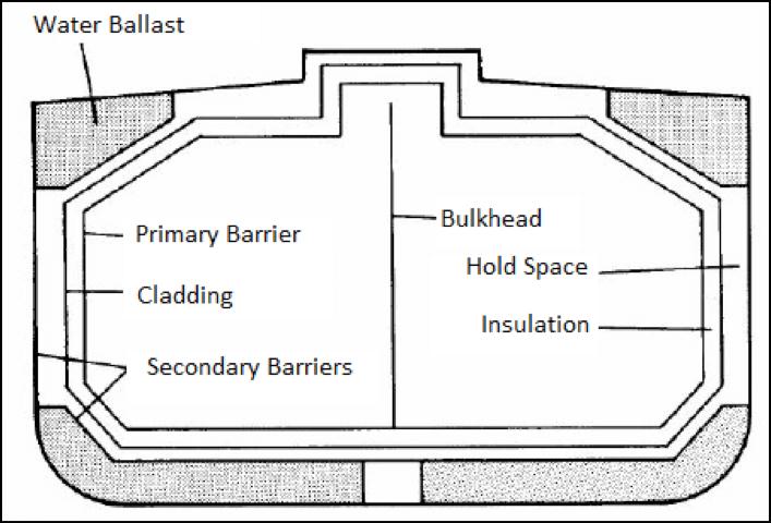
One important question that could arise, here, is that the tank in the midship section view seems to be an integral part of the hull. Why then, is this type of tanks categorised under Independent Tanks? To find the answer we need to have a closer look at how the tank is installed in the hull.
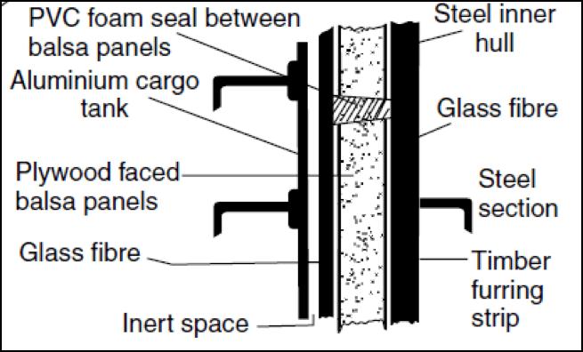
The above figure shows how the aluminum tank structure is not integrated to the inner hull of the methane carrier by means of any metal contact. The inner hull plating and aluminum tank plating are separated by layers consisting of timber, glass fibre, and balsa panels for insulation from external temperatures. The balsa panels are held together by plywood on both faces which are sealed using PVC foam seals. An inert space of 2 or 3 mm separates the inner glass fibre layer from the aluminum tank plate. This space is provided for insulation and also allows expansion and contraction of the tank structure. This type of non-welded integration makes this tank structurally independent in nature.
Type ‘B’ Tanks: The concept behind the design of such tanks is to have such a structure in which a crack can be detected long before the actual failure. This allows a time margin before the actual failure occurs. The methods used for design of such tanks include determination of stress levels at various temperatures and pressures by first principle analyses, determination of fatigue life of tank structure, and study of crack propagation characteristics. This enhanced design of such tanks requires on a partial barrier, that we will look into, soon.
The most common arrangement of Type ‘B’ tank is Kvaerner-Moss Spherical Tank, as shown below in Figure 4.
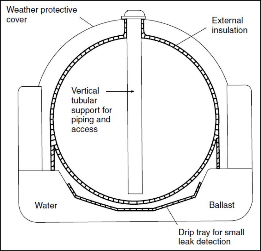
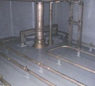
The tank structure is spherical in shape, and it is so positioned in the ship’s hull that only half or a greater portion of the sphere is under the main deck level. The outer surface of the tank plating is provided with external insulation, and the portion of the tank above the main deck level is protected by a weather protective layer. A vertical tubular support is led from the top of the tank to the bottom, which houses the piping and the access rungs.
As evident from the layout, any leakage in the tank would cause the spill to accumulate on the drip tray below the tank. The drip pan and the equatorial region of the tank are equipped with temperature sensors to detect the presence of LNG. This acts as a partial secondary barrier for the tank.
LNG is usually carried in this type of tanks. A flexible foundation allows free expansion and contraction according to thermal conditions, and such dimensional changes do not interact with the primary hull structure, as shown in Figure 5.

The following are the advantages of Kvaerner-Moss Spherical tanks:
- It enables space between the inner and outer hull (see Figure 4.) and this can be used for ballast and provided protection to cargo in case of side-ward collision damages.
- The spherical shape allows even distribution of stress, therefore reducing the risk of fracture or failure.
- Since ‘Leak before Failure’ concept is used in the design, it presumes and ensures that the primary barrier (tank shell) will fail progressively and not catastrophically. This allows crack generation to occur before it propagates and causes ultimate failure.
Type ‘C’ Tanks: These tanks are designed as cryogenic pressure vessels, using conventional pressure vessel codes, and the dominant design criteria is the vapour pressure. The design pressure for these tanks is in ranges above 2000 mbar. The most common shapes for these tanks are cylindrical and bi-lobe. Though Type ‘C’ tanks are used in both, LPG and LNG carriers, it is the dominant design in LNG carriers.
The following figures show the arrangements of cylindrical and bilobe tank arrangements in midship view. The cylinders can be either vertically or horizontally mounted, depending on the dimensions and spatial constraints of the ship. Note, in Figure 6, that the space between the two cylinders is rendered useless. Due to this, the use of cylindrical tanks is a poor use of the hull volume. In order to circumvent this, the pressure vessels are made to intersect, or bilobe tanks are used (Figure 7).
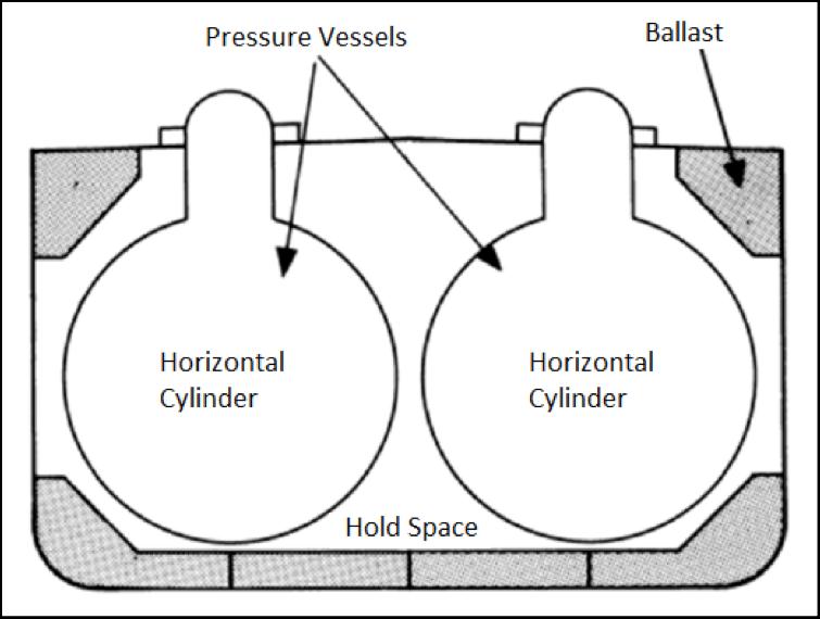
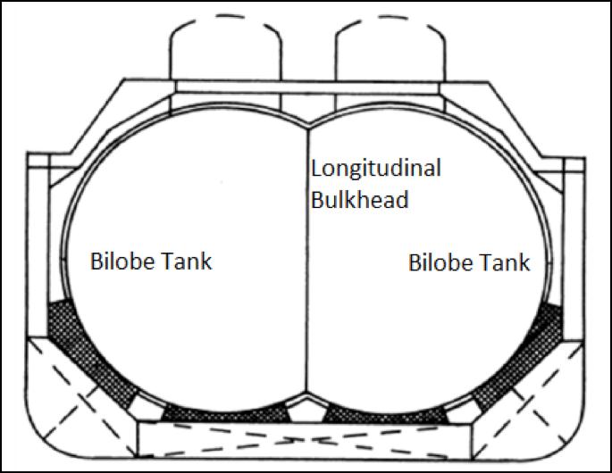
These types of tanks do not require a secondary barrier. Rather, to detect the leakage of cargo from the tanks, the hold space (refer to Figure 6) is filled with inert gas or dry air. Sensors placed in the hold space can detect the change in composition of the inert gas or dry air due to fuel vapour, and leakages can hence be detected and prevented. Bilobe tanks at the forward end of the ship are tapered at the end.
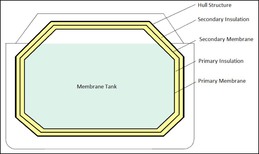
Membrane Tanks: Unlike independent tanks, membrane tanks are non-self-supporting structures. Their primary barrier consists of a thin layer of membrane (0.7 to 1.5 mm thick). The membrane is supported to the inner hull structure through an insulation that can range upto 10 mm thickness as per IMO IGC Code. Due to their non-self-supporting nature, the inner hull bears the loads imparted onto the tank. This way, the expansions and contractions due to thermal fluctuations are compensated by not allowing the stress to be taken up by the membrane itself. Membrane tanks are primarily used for LNG cargo.
Often, there are two layers (primary and secondary) of insulation and membranes placed alternatively. The most common types of membtane tanks are the ones designed and developed by two French companies Technigaz and Gaz Transport. The Tehnigaz system makes use of a stainless steel system that is constructed with corrugated sheets in such a way that one sheet is free to expand or contract independent of the adjacent sheet. The Gaz Transport system uses Invar as the primary and secondary membranes. Invar has low coefficient of thermal expansion, which makes corrugations unnecessary. The insulation is usually made of materials like Reinforced Polyurethane. In GTT membrane tanks, the primary membrane is made of Corrugated SUS 304, and the secondary membrane is made of Glued Triplex. Figure 8 illustrates the anatomy of twin-membrane tanks.
Some of the advantages of membrane tanks are as follows:
- They are generally of smaller gross tonnage, that is the space occupied within the hull is lower for a given cargo volume.
- Due to the above reason, maximum space in the hold can be used for cargo containment.
- Since the height of tanks above the main deck is significantly lesser compared to the cases of Moss tanks, membrane tanks provide allow visibility from the navigational bridge. This also allows a lower wheelhouse. This can be compared in Figures 10 and 11.
LPG Containment Systems: Unlike LNG, LPG cargo requires storage at conditions that are different from atmospheric conditions. The LPG containment systems are classified into three types, and each LPG carrier is designed according to any one of them.
Fully Pressurized Tanks: Propane, Butane and Anhydrous ammonia are carried in fully pressurized tanks. The capacity of these tanks is usually less than 2000 cubic meters. They are usually uninsulated cylindrical pressure vessels that are arranged partly below main deck level. Since these are Type C tanks, they often prevent complete utilization of under deck volume.
Semi Pressurized or Semi Refrigerated Tanks: Though the cargo carried by semi-pressurized ships are same as that of fully-pressurized ships, the volume of semi-pressurized ships is about 5000 cubic meters. These use Independent Type C tanks, and are constructed with ordinary grades of steel. The outer surface of these tanks are insulated, and refrigeration or reliquefication plants are installed on these ships to maintain the working pressure of the cargo. The most ommon types of tanks used for this purpose are cylindrical and bi-lobe type.
Fully Refrigerated Tanks: Fully Refrigerated gas carriers have a capacity of 10,000 to 1,00,000 cubic meters. The ships in the smaller size range are used to carry multiple types of cargo, whereas the larger ones are designed for a single type of cargo to be transported on a permanent route. The tanks used for this purpose is usually Type ‘A’ prismatic tanks that are sloped at the top end to reduce free surface effect, and sloped at the bottom to suit the shape of the bilge structure. They are usually divided longitudinally by a liquid-tight bulkhead, in order to reduce free surface effects further. These tanks are constructed with notch ductile steel, in order to be provided with maximum notch toughness at temperatures as low as -48 degrees Celsius, at which cargo like Propane is transported.
The number of gas carriers have increased drastically over the last ten years, owing to the increasing need for alternative fuel. These are usually high speed ships with fine hull-form, which makes it possible for extensive research opportunities to improve on hull efficiencies in order to achieve more power efficiency. A lot of research is also being carried out to design advanced cargo containment systems and concepts of adjoining bunkering systems are being developed by various countries that are opening themselves to extensive use of natural gas. Today, not all shipyards are equipped to design and build specialised ships like LPG and LNG carriers. This leaves a wide scope for designers and shipbuilders to develop skills and infrastructure to specialise in building these ships.
Methods of carriage of liquefied gases:
Reliquefaction with Intercooling: – Intercooling is used in conjunction with two stage compression. The first stage discharge is desuperheated in the intercooler and returned to the 2nd stage. The discharge from the 2nd stage is condensed in the condenser, and thence to the intercooler for further cooling. The condensate is returned to the cargo tank.
Non-condensable gases are separated out in the purge condenser and transferred by the cross over line to the collector and mast, or via the stripping or bottom distribution lines back into the cargo tank. If two or more tanks are being reliquefied simultaneously via one cargo system the distribution of condensate between the tanks is to be controlled manually.
If, during intercooling, there is insufficient condensate in the intercooler drum, additional liquid can be transferred from the cargo tank using the stripping/condensate line and a cargo pump. This is more likely to occur during the early stages of intercooling, or if the 2nd stage compression temperature is too high.
The condenser pressure is to be maintained at approximately 1 bar above the saturation pressure of condensate at the condensate temperature.
Reliquefaction without Intercooling:- Gas is drawn into the 1st stage of the compressor from the tank, via the surge drum (if fitted), compressed and discharged through the intercooler, but without cooling. The gas is liquefied in the condenser, expanded to tank pressure and returned via the spray or stripping/condensate line.
When several tanks are being cooled simultaneously by one reliquefaction plant, the operation should start with the tank having the highest pressure. Pressure is to be equalised before the tanks are interconnected. Also, when several tanks are being cooled simultaneously a careful watch must be kept on the liquid return to ensure equal filling.
-
 Cargo Solved MMD Past Papers Phase 1 Chief MatePrice range: ₹ 244.00 through ₹ 576.00
 -
 2nd Mate (F.G.) & NCV (NWKO) – Volume 3 (Cargo)₹ 219.00
 -
 Cargo Consolidated Notes for Phase 1 Chief Mate₹ 361.00
Cooling down of tanks:
- Prior to loading if returned with insufficient heel.
- After dry-docking, off-hire or during initial commissioning.
- LNG carriers with a typical capacity of, say, 153,000 m3 are loaded at about 12,000 m3/h.
- The volume of liquid LNG loaded displaces an equivalent quantity of vapour in the ship’s empty cargo tanks which is returned to the LNG storage tanks for processing in the site’s fuel gas system.
- This BOG will be available for typically 12 hours in each loading cycle. If the ship’s tanks are warm, loading takes a longer period of time as initially volumes of LNG are vaporised when they contact the warm sides of the LNG tanks, thereby cooling them.
- During loading, more than one LNG storage tank can be used simultaneously to load the carriers.
- Where jetty lines are long, the loading line generates significantly more BOG due to heat ingress from the pumps as a result of the larger duty.
- With relatively short jetty/transfer lines < 1 km, the heat component from LNG pumping is relatively small (typically around 5% of total BOG).
- However, for example where the LNG must move in excess of 7 km the pumping component becomes significantly larger at an estimated 45% of total BOG.
SIGTTO:
SOCIETY OF INTERNATIONAL GAS TANKERS AND TERMINAL OPERATORS (SIGTTO) was born out of a recognition that an industry specializing in the transport of liquefied gas needed to establish and promote the adoption and implementation of the very highest standards if it was first to win and then to maintain the confidence of the public at large. In acting as a beacon for quality and best practices, SIGTTO and its members have done just that, and that the excellent safety and pollution record of the sea borne gas transport industry to date defines it quite categorically as a highly responsible and effective sector.
By the late 1970s it was clear the international LNG business was set for a period of rapid expansion. A number of involved companies were therefore concerned to agree essential common standards for the industry, to aid its expansion, underpin public confidence and avoid a proliferation of unilaterally defined regulations. This group resolved to establish a body to draw together industry member companies in an effort to establish commonly agreed standards and best practice criteria. Hence the Society was formed and registered as a Bermuda Exempted Company (non-profit making) with limited liability in October 1979.
The Society was granted consultative status at the IMO in 1982. Formed originally with thirteen Members the Society has steadily grown over twenty years to a membership of more than 100 companies; representing virtually the whole of the world’s LNG trades and over half its LPG capacity.
PURPOSE: – The Society is the international body established for the exchange of technical information and experience, between members of the industry, to enhance the safety and operational reliability of gas tankers and terminals. The organization has been organized to encourage safe and responsible operation of liquefied gas tankers and marine terminals handling liquefied gas; to develop advice and guidance for best industry practice among its members and promote criteria for best practice to all who have responsibilities for, or an interest in, the continuing safety of gas tankers and terminals.
LNG as ship’s fuel:
- LNG as a ship fuel has great potential as fuel of choice for the future
- Clean burning – meets all current and future emission standards
- Existing Technology: Dual fuel engines in use on LNG carriers and coastal vessels/ferries in Europe
- LNG Fuel has lower cost today – about 30% lower than diesel fuel
- Vessel regulatory issues manageable
- LNG can be stored in tanks internal to the hull
- Variable Range Possible – Short Range on LNG (2,500 mi), Long Range with diesel fuel (dual-use)
Liquid Natural Gas (LNG) characteristics:-
- It is liquid only at cryogenic temperatures (-163°C) so it requires special storage tanks, pipe systems, and handling
- It will normally slowly evaporate when stored so a means to deal with boil off gas (BOG) is required – venting to air is not allowed
- When in gas state it can be explosive in an enclosed space at the right mixture with air – ventilation system needed
- It is clean burning so low SOx, Particulate, and NOx emissions can be achieved without add on hardware – emissions are compliant with ECA regulations
- LNG has half the density of diesel fuel so larger storage tanks for the same range are needed – tanks are not at high pressure so can be stored below deck, unlike CNG
Pre-Arrival Checklist:
The daily operation of a liquefied gas carrier involved potential hazards. It should be noted that cargo pipes, valves and connections and any point of leakage at the gas cargo may be intensely cold. Contact may cause severe cold burns.
Pressure should be carefully reduced and liquid cargo drained from any point of the cargo transfer system, including discharge lines, before any opening up or disconnecting is begun.
Some cargoes such as ammonia have a very pungent, suffocating odour and very small quantities may cause eye irritation and disorientation together with chemical burns. Seafarers should take this into account when moving about the vessel, and especially when climbing ladders and gangways. The means of access to the vessel should be such that it can be closely supervised and is sited as far away from the manifold area as possible. Crew members should be aware of the location of eye wash equipment and safety showers.
Everyone involved in liquefied natural gas trans- portation takes safety very seriously. There are many lives and a great deal of money at stake. Government and industry work together to make sure these ships are designed, maintained, and manned with safety in mind; industry maintains them with oversight by periodic government inspection, and government sets the standards for crew training.
The popular perception of liquefied natural gas is that it is inherently dangerous. While it possesses a set of hazards that need to be managed, when look- ing at the actual incidents involving liquefied natural gas, there are very few that put the surrounding area and public in danger. The rigorous attention to detail, coupled with the constantly emerging tech- nology, should continue to give LNG one of the bet- ter safety records for a hazardous material.
Within 5 days of the ship’s estimated time of berthing, the following checks and tests shall be carried out, and the results recorded. These records are to be made available to the gas terminal upon request.
- Deck water spray line.
- Water curtain
- Gas free condition of hold space.
- Alarm function of fixed gas detection equipment.
- Cargo gauging system and alarm set points.
- Emergency Shutdown System (ESD), all the relevant system shall be tested prior to arrival port and time needed to shut should be confirmed around 25 up to 30 seconds.
- Operation of cargo system remote control valves and their position indicating systems.
- Confirm Cargo transfer emergency stops fully operational and date of last test.
- Confirm tank high level and pressure alarms operational.
- Confirm that remotely operated manifold valves have been operated through a complete open/closed cycle, functioning and advise valve type(ball, gate, etc)and actual closing time. The corresponding records shall be produced by the master on the ship arrival at berth. Any defects or deficiencies must be reported to the terminal as an addendum to the Pre-Arrival information notice.
- (11) Deep well cargo pump and booster pump mechanical seals are free of oil leaks.
ICS data sheets:
- ICS data sheets outlines the main characteristics of individual cargoes, and the action to be taken in an emergency.
- Matters relating solely to maintenance of the purity of individual cargoes and their condition during carriage have not been included.
- It’s something like material safety data sheet of gas cargo.
- With respect to ICS Data Sheet – The IMO Codes require the following information to be available to every ship and for each cargo:
- The master must only load a cargo which is listed on his certificate of fitness.
- Data sheets for these cargoes should be on board.
- The master and all those concerned should use the data sheet and any other relevant information to acquaint themselves with the characteristics of each cargo to be loaded. If the cargo to be loaded is a mixture (e.g LPG), information on the composition of the mixture should be sought; the temperature and pressure readings in the shore tank can be used to verify this information.
- Special notes should be made of any contaminants that may be present in the cargo, e.g.”water”.
- Ref: SIGTTO publication for gas carrier appendix 1
SEMI-REFRIGERATED OR PRESSURE CARGOES:
Loading:
- This operation follows the general principles very closely. The shore loading hose, and, if available, the vapour return line hose, are connected to the liquid and vapour line connections at the cargo manifold.
- Loading is effected through the liquid line, and pressure relief, etc., through the vapour return line. When the vessel arrives at the loading terminal, her tanks should be:
- Empty of liquid, but under suitable pressure of vapour from her previous cargo (gassed-up); or gas-free, but under the maximum vacuum possible (usually in the vicinity of 80 per cent.).
- An increasing number of terminals insist that the vessel’s cargo tanks be inerted before the final vacuum is created prior to loading.
- If the vessel’s cargo tanks are full of vapour at a suitable pressure (gassed up), loading can start at once.
- This being the simpler of the two cases given above, it will be described first.
- As the liquid enters the tank, the vapour trapped in the space above the liquid will be compressed, become supersaturated and condense.
- If a vapour return line has been provided, any excess pressure can be returned ashore.
- If no vapour return line is provided, then the pressure can be relieved in the following ways: firstly, by spraying part of the cargo into the tank, secondly by refrigeration and finally, if these methods fail, by allowing the excess pressure to escape into another tank.
- In this connection, it is not advisable to attempt loading all the, cargo through the sprays because to do so places an unnecessary restriction on the line.
- The sprays should be used only for the purpose of providing a larger surface area upon which the supersaturated vapour condenses.
- In the second case, when the vessel arrives alongside gas-free and under an 80 per cent. vacuum, the first step is to break the vacuum with vapour taken from shore, and raise the pressure within the tanks to a suitable level.
- If a vapour return line is provided, this is simple. If no vapour return line is provided, the cargo tanks can be gassed-up by either using the vaporiser, or by spraying very small quantities of liquid into the tank via the fine spray line in such a manner that the liquid droplets evaporate before they come into contact with the tank’s sides.
- This effectively gasses-up the tank, but if the ship arrived with an 80% vacuum, 20 per cent. of the ship’s capacity will be occupied by incondensibles at atmospheric pressure, the incondensibles being either air or inert gas (usually nitrogen).
- However, under pressure, the physical space occupied by these incondensibles is much less.
- For example, under 3 bars pressure (gauge) they would occupy a quarter of the space they would occupy at atmospheric pressure.
- If the incondensibles remaining in the tanks consist of air, the atmosphere within the tank will be very “over-rich” after gassing-up, but to dispose of the incondensibles by the separator using the reliquefaction process involves putting a gas/air mixture through the compressors which involves a risk, however small, of an explosive mixture being passed through the compressors.
- For this reason, some refineries insist on the cargo tanks being inerted prior to creating the final vacuum before loading, but many loadings have taken place over a long-period without any accident being attributed to this cause, and the danger may be more the theoretical than real.
- The usual loading programme is to load the lower tanks first, and to complete loading in the upper tanks. The loading rate depends upon the diameter of the liquid lines and the number of valves open. When the number of valves opened towards the completion of cargo is reduced, the loading rate should be reduced accordingly.
- Soundings of all tanks should be checked at regular intervals to ascertain the loading rate, and also to ensure that no liquid is entering a tank which has been completed, or not started.
- This is very important because it is an old maxim that it is the unmatched tank which always overflows.
- To load a very warm cargo from fully pressurized storage at ambient temperature into a semi-refrigerated ship, the reliquefaction plant must be started up and run at its maximum capacity to cool the cargo as it comes on board.
- The usual technique is so to adjust the loading rate as to maintain a pressure in the tanks below the safety valve relief setting.
- This can be achieved by maintaining a constant pressure at the loading manifold by frequently adjusting the manifold valve.
- Experience will soon show the best pressure to maintain and it is usually very close to the maximum pressure at which it is intended to load the product.
- The loading manifold pressure gives a much better indication of the valve adjustment needed, than watching the tank pressures, and adjusting the loading rate by guesswork.
Deep Well Pump:
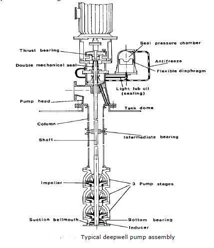
- Deepwell pump is the pump type that is often used on gas tankers.
- Deepwell pumps are pumps with a long shaft between the driving motor and the pump.
- The shaft goes inside the tank’s discharge pipe from the pump up to the tank dome.
- The discharge pipe is a solid pipe that goes up through the tank and out to the flange on the tank dome to the liquid line.
- The discharge pipe is constructed with several lengths with pipes, and there is a shaft bearing on each flange.
- The bearings are lubricated and cooled down by the liquid that is pumped from the tank.
- It is very important not to run the pump without liquid.
- This may result in damage of bearings and then the shaft.
- The motor that drives the pump is either electric or hydraulic.
- There is a mechanical sealing device between the motor and the discharge pipe in the cargo tank.
IGC Code:
- The Code which applies to new gas carriers (built after 30th June 1986) is the International Code for the Construction and Equipment of Ships Carrying Liquefied Gases in Bulk.
- In brief, this Code is known as the IGC Code.
- The IGC Code, under amendments to Safety of Life at Sea Convention (SOLAS), is mandatory for all new ships.
- As proof that a ship complies with the Code, an International Certificate of Fitness for the Carriage of Liquefied Gases in Bulk should be on board.
- In 1993, the IGC Code was amended and the new rules came into effect on 1st July 1994.
- Ships on which construction started on or after 1st October 1994 should apply the amended version of the Code but ships built earlier may comply with previous editions of the IGC Code.


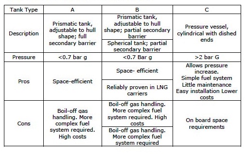
Main characteristics of the different tank types:
Differentiate between Integral Tanks & Membrane Tanks:
| INTEGRAL TANKS | MEMBRANE TANKS |
| Integral tanks form a structural part of the ship’s hull and are influenced by the same loads which stress the adjacent hull structure, and in the same manner. | Membrane tanks are not self-supporting tanks; they consist of a thin layer (membrane), Normally not exceeding 1 mm thick, supported through insulation by the adjacent hull structure. |
| This form of cargo containment is not normally allowed if the cargo temperature is below -10OC. | The rounded parts of the layer are designed to accommodate thermal expansion and contraction, and other types thereof. |
| This containment system is partly used on some LPG ships dedicated to the carriage of butane. | The semi-membrane design has been developed for carriage of LNG, and the material of construction is 9% nickel steel or aluminium. |
Difference between Fully Refrigerated & Semi – Refrigerated / Semi – Pressurised Gas Carrier:
| Fully Refrigerated Gas Carrier | Semi – Refrigerated / Semi – Pressurised Gas Carrier |
| Shape:- The tankers have prismatic-shaped cargo tanks | Shape:- The tanks are cylindrical in shape and of a thinner construction than the pressurised vessels. |
| Cargo capacity: – The ships are typically in the range 15,000m3 – 85,000m3, with three common sizes for LPG/Ammonia trades of 30,000m3, 52,000m3 and 80,000m3. | Cargo capacity: – The Ships typically ranges up to 5,000 m3 in size. Their construction is based on carrying propane at a pressure of 8.5 kg/cm2, and a temperature of -10°C. |
Various types of Liquefied Gas Carriers considering Survival Capacity as per IGC code:
IGC Code 2.1.2: Ships subject to the Code shall be designed to one of the following standards:
- A type 1G ship is a gas carrier intended to transport the products indicated in chapter 19 that require maximum preventive measures to preclude their escape.
- A type 2G ship is a gas carrier intended to transport the products indicated in chapter 19, that require significant preventive measures to preclude their escape.
- A type 2PG ship is a gas carrier of 150 m in length or less intended to transport the products indicated in chapter 19 that require significant preventive measures to preclude their escape, and where the products are carried in type C independent tanks designed (see 4.23) for a MARVS of at least 0.7 MPa gauge and a cargo containment system design temperature of -55°C or above. A ship of this description that is over 150 m in length is to be considered a type 2G ship.
- A type 3G ship is a gas carrier intended to carry the products indicated in chapter 19 that require moderate preventive measures to preclude their escape.
Therefore, a type 1G ship is a gas carrier intended for the transportation of products considered to present the greatest overall hazard and types 2G/2PG and type 3G for products of progressively lesser hazards. Accordingly, a type 1G ship shall survive the most severe standard of damage and its cargo tanks shall be located at the maximum prescribed distance inboard from the shell plating.
Types of Gas Carriers:
Gas carriers range in capacity from the small pressurised ships of between 500 and 6,000 m3 for the shipment of propane, butane and the chemical gases at ambient temperature up to the fully insulated or refrigerated ships of over 100,000 m3 capacity for the transport of LNG and LPG. Between these two distinct types is a third ship type — the semi-pressurised gas carrier. These very flexible ships are able to carry many cargoes in a fully refrigerated condition at atmospheric pressure or at temperatures corresponding to carriage pressures of between five and nine bar.
Fully Pressurised ships:
- Today, most fully pressurised LPG carriers are fitted with two or three horizontal, cylindrical or spherical cargo tanks and have capacities up to 6,000 m3.
- However, in recent years a number of larger capacity fully-pressurised ships have been built with spherical tanks, most notably a pair of 10,000 m3 ships, each incorporating five spheres, built by a Japanese shipyard in 1987.
- Fully pressurised ships are still being built in numbers and represent a cost-effective, simple way of moving LPG to and from smaller gas terminals.
Semi-pressurised ships:
- These carriers, incorporating tanks either cylindrical, spherical or bi-lobe in shape, are able to load or discharge gas cargoes at both refrigerated and pressurised storage facilities.
- The existing fleet of semi-pressurised ships comprises carriers in the 3,000-15,000 m3 size range, although there is a notable exception — a ship of 30,000 m3 delivered in 1985.
- Ethylene and gas/chemical carriers Ethylene carriers are the most sophisticated of the semi-pressurised tankers and have the ability to carry not only most other liquefied gas cargoes but also ethylene at its atmospheric boiling point of –104°C. The first ethylene carrier was built in 1966 and as of 1995, there were about 100 such ships in service ranging in capacity from 1,000 to 12,000 m3.
- These ships feature cylindrical, insulated, stainless steel cargo tanks able to accommodate cargoes up to a maximum specific gravity of 1.8 at temperatures ranging from a minimum of –104°C to a maximum of +80°C and at a maximum tank pressure of 4 bar.
- The ships can load or discharge at virtually all pressurised and refrigerated terminals, making them the most versatile gas carriers in terms of cargo-handling ability.
Fully Refrigerated Ships:
- The 1960s also saw another major development in gas carrier evolution — the appearance of the first fully refrigerated ship, built to carry liquefied gases at low temperature and atmospheric pressure between terminals equipped with fully refrigerated storage tanks. The first purpose-built, fully refrigerated LPG carrier was constructed by a Japanese shipyard, to a United States design, in 1962.
- The ship had four prismatic-shaped (box-like) cargo tanks fabricated from 31⁄2 per cent nickel steel, allowing the carriage of cargoes at temperatures as low as –48°C, marginally below the atmospheric boiling point of pure propane. Prismatic tanks enabled the ship’s cargo carrying capacity to be maximised, thus making fully refrigerated ships highly suitable for carrying large volumes of cargo such as LPG, ammonia and vinyl chloride over long distances.
- Today, fully refrigerated ships range in capacity from 20,000 to 100,000 m3.
- The main types of cargo containment system utilised on board modern fully refrigerated ships are independent tanks having rigid foam insulation. Older ships can have independent tanks with loosely filled perlite insulation. In the past, there have been a few fully refrigerated ships built with semi-membrane or integral tanks and internal insulation tanks, but these systems have only maintained minimal interest.
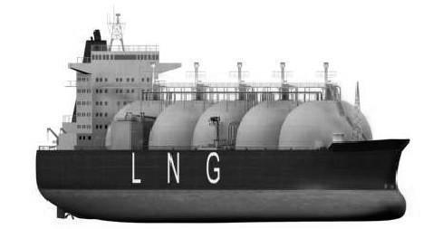
Liquefied Natural Gas (LNG) Carriers:
- At about the same time as the development of fully refrigerated LPG carriers was taking place, naval architects were facing their most demanding gas carrier challenge, this was the transport of LNG.
- Natural gas, another clean, non-toxic fuel, is now the third most important energy source in the world, after oil and coal, but is often produced far from the centres of consumption. Because a gas in its liquefied form occupies much less space, and because of the critical temperature of liquefied methane, the ocean transport of LNG only makes sense from a commercial viewpoint if it is carried in a liquefied state at atmospheric pressure; as such, it represents a greater engineering challenge than shipping LPG, mainly because it has to be carried at a much lower temperature; its boiling point being –162°C.
- LNG containment system technology has developed considerably since those early days: now about one-half of the LNG carriers in service are fitted with independent cargo tanks and one-half with membrane tanks.
- The majority of LNG carriers are between 125,000 and 135,000 m3 in capacity. In the modern fleet of LNG carriers, there is an interesting exception concerning ship size.
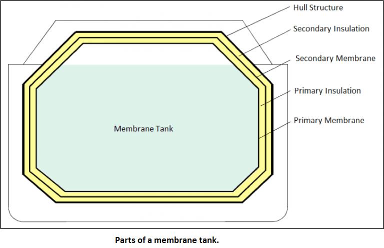
Diagram about LNG Ships Membrane Tank Structure:
- Unlike independent tanks, membrane tanks are non-self-supporting structures. Their primary barrier consists of a thin layer of membrane (0.7 to 1.5 mm thick).
- The membrane is supported to the inner hull structure through an insulation that can range upto 10 mm thickness as per IMO IGC Code. Due to their non-self-supporting nature, the inner hull bears the loads imparted onto the tank.
- This way, the expansions and contractions due to thermal fluctuations are compensated by not allowing the stress to be taken up by the membrane itself. Membrane tanks are primarily used for LNG cargo.
- Often, there are two layers (primary and secondary) of insulation and membranes placed alternatively.
- The most common types of membrane tanks are the ones designed and developed by two French companies Technigaz and Gaz Transport. The Tehnigaz system makes use of a stainless steel system that is constructed with corrugated sheets in such a way that one sheet is free to expand or contract independent of the adjacent sheet. The Gaz Transport system uses Invar as the primary and secondary membranes.
- Invar has low coefficient of thermal expansion, which makes corrugations unnecessary.
- The insulation is usually made of materials like Reinforced Polyurethane.
- In GTT membrane tanks, the primary membrane is made of Corrugated SUS 304, and the secondary membrane is made of Glued Triplex. Below Figure illustrates the anatomy of twin-membrane tanks.
Some of the advantages of membrane tanks are as follows:
- They are generally of smaller gross tonnage, that is the space occupied within the hull is lower for a given cargo volume.
- Due to the above reason, maximum space in the hold can be used for cargo containment.
- Since the height of tanks above the main deck is significantly lesser compared to the cases of Moss tanks, membrane tanks provide allow visibility from the navigational bridge. This also allows a lower wheelhouse.
Preparation Procedure for loading LNG cargo:
Loading LNG cargo after dry docking:
LNG is a cryogenic substance and its main component is methane. It gasifies violently when directly introduced into a cargo tank at ambient temperature, rapidly increases the internal pressure of the cargo tank and makes the atmosphere into a flammable condition. In addition, the cargo tank is rapidly cooled, resulting tremendous thermal stress on cargo tank skins and cargo piping systems.
To avoid such damages, the preparatory work for cargo loading after dry docking must be done in the following sequence. During dry dock all the compartments of an LNG carrier are kept gas free.
After leaving the dry dock the vessel has to be prepared to load cargo, for that the following points to be considered with priority.
Drying of Cargo Tank:
During dry docking or inspection, cargo tanks which have been opened and contained humid air, must be dried to avoid the formation of ice when they are cooled down and the formation of corrosive agents if the humidity combines with sulfur and nitrogen oxides which might be present in excess in the inert gas.
The drying operation need not be performed independently by using dry air, instead during inerting operation by supplying dry inert gas, drying operation can be achieved. During such operation special attention is required to the delivery temperature of inert gas to prevent condensation of humid air inside the tank.
Dry air, with a dew of -70ºC to -40ºC, can be produced by the onboard IGG system:
i) It is essential that cargo tanks are thoroughly inspected for cleanliness, free of liquid, any loose objects and all fittings are properly secured. Once this inspection has been completed, the cargo tank should be securely closed and drying operation can be started
ii) During drying operation, measure the atmosphere at different levels at regular intervals. When the dew point of the cargo tank drops below than the planned temperature, finish the drying operation.
Drying of Hold Spaces:
The drying operation of a hold space is carried out in order to prevent tank insulation damage due to condensation of moisture inside it prior to initial cool down operation and periodically during a voyage. Fresh air is dehumidified by the IGG and sent to a hold space as dry air with a dew point of -70ºC to -40ºC through its bottom section, humid air inside the hold space is released through the vent pipe provided in the upper portion of the tank. The hold space should be maintained at a higher pressure than the atmospheric pressure.
Operation Procedures and Precautions:
- Before delivering dry air into a hold space, completely dry up the bottom section of the hold space, particularly the bilge well.
- When drying a hold space after completing the inerting operation of a cargo tank, purge relevant equipments and Inerting/aerating lines with dry air to prevent the ingress of inert gas into the hold space. This is because the hold space holding dry air sent into it is kept almost sealed till the next dry docking and, in addition, about 15% CO2 gas is present in the inert gas, which may corrode aluminium cargo tanks and destroy insulation materials.
- During drying operation, measure the atmosphere at different levels at regular intervals. When the dew point of the hold space drops below than the planned temperature, finish the drying operation.
- Inerting of Cargo Tanks:
Before introducing the cargo into the tanks, the moisture content and oxygen content in the tanks shall be reduced simultaneously.
Cargo tanks filled with air shall be dried and inerted with inert gas supplied from the inert gas generator on board. Inert gas shall be led into the bottom of the cargo tank through the liquid filling line and displaced air shall be vented to the atmosphere through the vapour line and the vent mast. Drying and inerting shall be finished when the dew point and also the oxygen content in the cargo tank are less than the planned level.
The dew point and oxygen content shall be periodically measure by a portable instrument at the sampling lines in way of cargo tank dome.
- Inerting of Annular Space for Moss type vessels:
The space between the surface of a cargo tank and insulation is called annular space, insulation space or wedge space. Annular Space is inerted with nitrogen gas and continuously supplied from N2 generator through the N2 bleed line in service in order to ensure adequate path in the insulation space for the gas detection system.
A safety valve is installed in the N2 bleeding line of each hold in order to avoid over pressure of the insulation space.
- Inerting Inter Barrier Spaces (IBS) and Insulation Spaces (IS) for Membrane type vessels:
The space between the primary and the secondary barrier is called inter-barrier space (IBS). The space between the secondary barrier and the inner hull is called insulation space (IS). The pressure in these spaces shall be regulated at a pressure slightly above atmospheric pressure in order to prevent any air ingress.
In normal operation, IBS and IS shall be purged with nitrogen in relation with atmospheric pressure variations and cooling or warming of the spaces during loading or unloading, and IBS should be continuously purged with nitrogen if gas is detected by micro-leakage of the membrane.
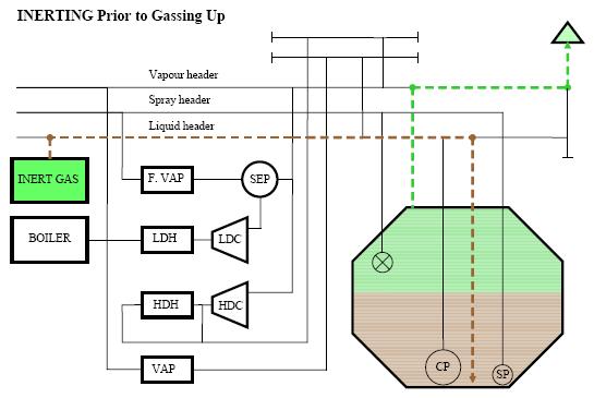
- Gassing-up:
After lay-up or dry dock, the cargo tanks are filled with inert gas or nitrogen. If the purging has been done with inert gas, the cargo tanks have to be gassed up and cooled down when the vessel arrives at the loading terminal. This is because, inert gas contains about 14% carbon-dioxide, which will freeze at around -60ºC and produces a white powder which can block valves, filters and nozzles.
During gassing up, the inert gas in the cargo tanks is replaced with warm LNG vapor. This is done to remove carbon dioxide and to complete drying of the tanks.
- Supply of LNG for Gassing up:
LNG liquid is supplied from the terminal to the liquid manifold where it passes to the stripping/spray header via the appropriate ESDS liquid valve. It is then fed to the main vaporizer and the LNG vapour produced is passed at a temperature warmer than the dew point temperature existing within the cargo tanks through the vapor header and into each tank via the vapor suction fitted in the upper part of the tank.
This method of gassing up is called “Piston Flow Method”. In this the lighter specific gravity LNG vapor is injected from top and the heavier IG is displaced from bottom.
- Initial Cool Down:
Cool down is an operation to pre-cool cargo tanks and lines required before taking on cryogenic LNG. Cargo tank cool down is carried out by spraying LNG through the spray nozzles of each cargo tank, using LNG received from the shore terminal. The cool down operation from an ambient temperature (from a condition after gassing up) to a planned temperature, is called ‘initial cool down’ and is to be differentiated from an ordinary cool down operation carried out on ballast voyage.
Before LNG can be introduced into the cargo system of an LNG vessel, the system, and in particular the cargo tanks, have to be cooled down to a temperature close to that of the LNG which is to be loaded. The reasons for this are as follows:
- Vapor Generation:
If LNG is introduced directly into warm tanks, the LNG will almost immediately turn into vapour. LNG has a liquid to gas expansion ratio 1: 600. Therefore, to enable the liquid to be loaded into the tank at a reasonable loading rate, necessity of large compressors would be required to remove the vapour generated in the process.
By reducing the cargo tank temperature, the amount of heat that is available to transfer into and heat the LNG is minimized. Consequently the amount of vapour generated can be maintained within reasonable limits.
- Cargo Tank Material:
Most cargo tanks are constructed of stainless steel which is a material, that retains its flexibility and strength characteristics over the temperature range being considered (-180ºC – 50ºC). However problems could occur if the material is subjected to very local and rapid cooling such as when a small droplet of LNG comes into contact with a warm tank wall. Because of the transfer of the heat from the wall into the liquid, the temperature at the particular point will decrease rapidly causing large thermal stresses to arise between the point and the surrounding material. This could lead to stress cracking.
- Pipe Tower Construction:
The tower which supports the pipe-work within the tank is constructed of stainless steel bars. If subjected to rapid cooling thermal stress within the material can be excessive, leading to the material cracking.
All three reasons are of equal importance as each, if not carefully controlled, can have a significant impact on the tank structure and overall safety of the vessel.
Loading Operation:
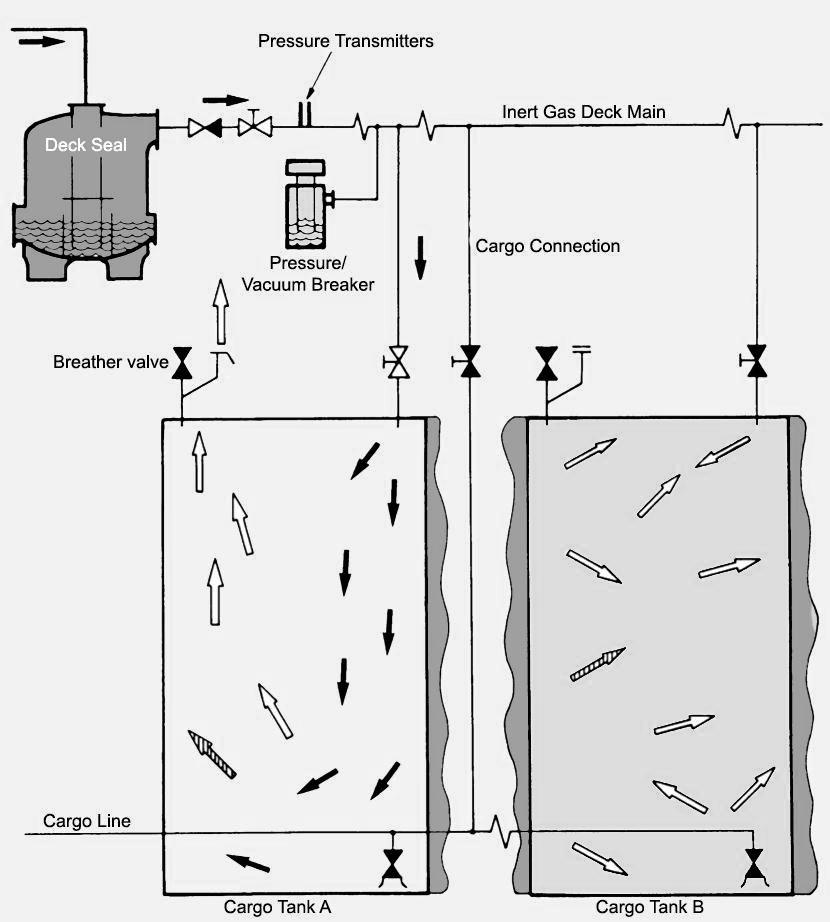
- LNG is loaded via the loading manifolds to the liquid header and then to each tank filling line. The boil-off and displaced vapour leave each tank via the vapour suction to the vapour header. The vapour is initially free-flowed to shore via vapour crossover manifold and, as tank pressure rises, one compressor is brought into operation to increase the gas flow to shore and limit the vapour main and cargo tank pressure.
- As the loading rate increases, it is important to monitor the tank pressures and to start one HD compressor. If the compressors are unable to cope with the volume of boil-off and displaced gas, it will be necessary to reduce the loading rate.
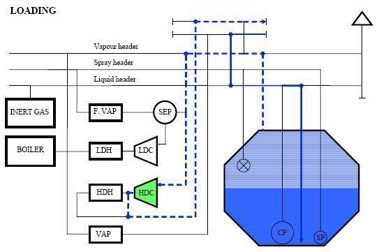
Fig: LNG bulk loading diagram
Bulk loading:
- When all lines and valves are fully cooled the vessel can commence ramping up the loading rate in the sequence agreed with the terminal. Deballasting should be commenced in accordance with the cargo plan. The cargo should be evenly distributed during the loading.
- Ensure the HD compressors are adjusted in line with loading rate to ensure that the tank vapour pressure remains at a level safely below the lifting pressure of the relief valves. Ensure Nitrogen system is performing correctly.
- Moss vessels will require the temperature gradient (with particular reference to the equator) to remain within certain limits, the tank temperatures are therefore to be closely monitored. Hourly temperatures are to be recorded in order that if required the vessel can verify that temperature has stayed within the manufacturers tolerances.
- If not already started membrane ships should start appropriate cofferdam heating. Communications with the terminal should be tested on a frequent basis. Remote gauging devices and valve position indicators should be verified against local readouts at regular intervals during the operation. Moorings should be diligently attended and vessel movement with respect to loading arms closely monitored, if required additional persons are to be called to assist with the moorings. If at any time the OOW is in doubt a senior officer or the Master should be called.
Topping off:
- As the vessel approaches completion of cargo operations the tanks should be staggered in line with the cargo plan, typically this would leave a gap of 10 to 15 minutes between completion of each tank. The terminal is to be notified well in advance and in line with the agreed procedure that the vessel is topping of and will need to reduce loading rate. Notification should be made at least 30 minutes before reducing rate.
Note: Membrane tanks normally fill to 98% whereas Moss vessels normally fill to 99.5%. On all vessels the independent alarms activate at preset filling levels, the upper alarm activates the ESD if previous alarms are ignored.
Deballasting:
- The deballasting operation is carried out simultaneously with the cargo loading operation. Before any de-ballasting commences, all ballast surfaces should be visually checked and confirmed as free from oil or other pollutants. This check must be carried out through inspection hatches / tank lids. This is particularly important for ballast tanks which are situated adjacent to fuel oil tanks. If fitted, gas detection / sampling systems may not indicate the presence of hydrocarbons particularly in small quantities.
- Deballasting is initially carried out by gravity discharge until the level in the ballast tanks approach the vessels water line when the ballast pumps are used.
- The ballast should be adjusted to keep a small stern trim to aid with the stripping of the ballast tanks. The flow rate of the ballast should be adjusted to keep the ship within 1 meter of the arrival draft or as specified by the terminal. Deballasting should normally be completed before the start of the topping off of the cargo tanks.
Filling Rate of Cargo Tanks:
- The IGC Code (International Code for the Construction and Equipment of Ships Carrying Liquefied Gases in Bulk) came into force on July 1, 1986, in accordance with the International Convention on the Safety of Life at Sea, 1983 (the 1974 SOLAS Convention, as amended in 1983), and, following this, the Regulations Relating to the Carriage and Storage of Dangerous Goods by Ship was revised in Japan. The IGC Code contains a chapter for “Filling Limits for Cargo Tanks”.
- LNG carriers registered in Japan are NK-class ships and constructed on the basis of NK’s “Rules and Guidance for the Survey and Construction of Steel Ships – Part N”. These rules reflect the IGC Code, as it is, and, as a result, our LNG carriers, though built before the enforcement of the ’83 SOLAS Convention, meet requirements for new ships in the IGC Code.
Behaviour of LNG in the Cargo Tanks:
- When loaded in the cargo tanks, the pressure of the vapour phase is maintained substantially constant, slightly above atmospheric pressure.
- The external heat passing through the tank insulation generates convection currents within the bulk cargo, causing heated LNG to rise to the surface where it vaporizes.
- The heat necessary for vaporization comes from the LNG, and as long as the vapour is continuously removed by maintaining the pressure as substantially constant, the LNG remains at its boiling temperature.
- If the vapour pressure is reduced by removing more vapour that is generated, the LNG temperature will decrease. In order to make up the equilibrium pressure corresponding to its temperature, the vaporization of LNG is accelerated, resulting in an increase heat transfer from LNG to vapour.
- If the vapour pressure is increased by removing less vapour than is generated, the LNG temperature will increase. In order to reduce the pressure to a level corresponding to the equilibrium with its temperature, the vaporization of LNG is slowed down and the heat transfer from LNG to vapour is reduced.
- LNG is a mixture of several components with different physical properties, particularly the vaporization rates; the more volatile fraction of the cargo vaporizes at a greater rate that the less volatile fraction. The vapour generated by the boiling of the cargo contains a higher concentration of the more volatile fraction than the LNG.
Preparation for loading LNG cargo – Inerting of Cargo Tanks:
- Inert gas (e.g. nitrogen) or mixture of gases, containing insufficient oxygen to support combustion. The introduction of inert gas into a space to reduce and maintain the oxygen content at a level at which combustion cannot be supported- with an Oxygen content of less than 1% and a dewpoint of less than -45 deg C is typically introduced into the bottom of cargo tank through the filling pipe.
- The Inert Gas is displaced from the top of each tank through the dome and vapour header and is discharged from the vent mast. During this process all the cargo piping and equipment forming part of the cargo system is to be purged with Inert Gas.
- Warning – Inert Gas will not sustain life. Great care is to be taken to ensure the safety of all personnel involved with any part of the operation including those working with the Inert Gas plant.
Below is our guideline prior loading LNG cargo on board:
Inerting of Cargo Tanks:
- Vapours from the last cargo in the system are displaced by inert gas from the ship’s inert gas generator, or by pure nitrogen from shore. If the ship’s inert gas is used, the cargo piping system from the tank should be opened to the vent before the inert gas supply is connected as an additional precaution against the possible backflow of flammable vapour to the generator.
- Regulations regarding venting of cargo vapour in port should be observed. Such regulations may require that vented cargo vapours should be led to a flare or vent stack ashore. Inerting is continued until the required dew point or concentration of cargo vapour or oxygen level has been reached.
- Before introducing the cargo into the tanks, the moisture content and oxygen content in the tanks shall be reduced simultaneously.
- Cargo tanks filled with air shall be dried and inerted with inert gas supplied from the inert gas generator on board. Inert gas shall be led into the bottom of the cargo tank through the liquid filling line and displaced air shall be vented to the atmosphere through the vapour line and the vent mast. Drying and inerting shall be finished when the dew point and also the oxygen content in the cargo tank are less than the planned level.
- The dew point and oxygen content shall be periodically measure by a portable instrument at the sampling lines in way of cargo tank dome.
Inerting of Annular Space for Moss type vessels:
- The space between the surface of a cargo tank and insulation is called annular space, insulation space or wedge space. Annular Space is inerted with nitrogen gas and continuously supplied from N2 generator through the N2 bleed line in service in order to ensure adequate path in the insulation space for the gas detection system.
- A safety valve is installed in the N2 bleeding line of each hold in order to avoid over pressure of the insulation space.
Inerting Inter Barrier Spaces (IBS) and Insulation Spaces (IS) for Membrane type vessels:
- The space between the primary and the secondary barrier is called inter-barrier space (IBS). The space between the secondary barrier and the inner hull is called insulation space (IS). The pressure in these spaces shall be regulated at a pressure slightly above atmospheric pressure in order to prevent any air ingress.
- In normal operation, IBS and IS shall be purged with nitrogen in relation with atmospheric pressure variations and cooling or warming of the spaces during loading or unloading, and IBS should be continuously purged with nitrogen if gas is detected by micro-leakage of the membrane.
The Nitrogen provides a dry and inert medium for the following purposes:
- To prevent formation of flammable mixture in the event of any LNG leak.
- To permit easy detection of an LNG leak through a barrier.
- To prevent corrosion.
“BOIL OFF” on an LNG:
LNG Boil-off Vapour Handling System:
- Although it is technically quite feasible to re-liquefy LNG boil off vapours, the plant required is complex and expensive and to date has not been installed on board such ships. Instead, the boil off is used as fuel for the ship’s boiler during the sea passage.
- LNG, the predominant component of which is methane, is the only cargo used as fuel in this manner. Methane vapour is lighter than air at ambient temperature, whereas LPG vapours are always heavier than air. Therefore, in the event of leakage, methane tends to be dispersed upwards more easily.
- Where methane boil-off is used as fuel, it is very important to ensure that the correct procedures and safety precautions are followed.
- LNG ships use steam turbine driven axial flow compressors to handle boil off vapours produced during cool down, loading and during loaded and ballast passage. Normally, a low duty compressor handles the boil off whilst on passage, a high duty compressor handles vapours produced during cool-down and loading, returning these vapours to shore.
- Whilst on passage, the low-duty compressor collects the boil-off from a common header connected to each cargo tank, passing it through steam heater to the poop front. Here it enters a specially designed double duct trunking system heading to the boiler or diesel engine dual fuel systems. This trunking is continuously monitored for leakage and has automatic shutdown protection in the event of system malfunction or leakage. The compressors are provided with surge controls and protective devices.
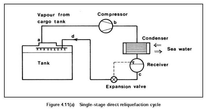
Single-Stage Direct Cycle:
- The single-stage direct cycle system is particularly suited to the semi-pressurised carrier.
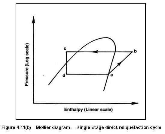
- A simplified diagram of single-compression reliquefaction is shown in Figures 4.11(a) and (b).
- This cycle is suitable where suction pressures are relatively high, as in the carriage of semi-pressurised products. Boil-off vapours from the cargo tank are drawn off by the compressor — (a) in the diagrams. Compression increases the pressure and temperature of the vapour — to (b) in the diagrams. The high temperature allows it to be condensed against sea water in the condenser — at (c) in the diagrams.
- The condensed liquid is then flashed back to the tank via a float controlled expansion valve at (d) in the diagrams.
- The liquid/vapour mixture being returned the cargo tank may be either distributed by a spray rail at the top of the cargo tank or taken to the bottom of the tank to discourage re-vaporisation.
- The spray rail is normally used when the tank is empty and bottom discharge when the tank is full (see also 2.19 and Figure 2.16).
Explanation on Heel maintained on LPG: Use of Coolants on LPG:
Heel on LPG: It is frequent practice in some refrigerated trades to retain a small quantity of cargo on board after discharge and the amount retained is known as the Heel. This product is used to maintain the tanks at reduced temperature during the ballast voyage but this procedure only applies when the same grade of cargo is to be loaded at the next loading terminal.
In general, the quantity retained on board as a Heel depends on:—
- Commercial agreements
- The type of gas carrier
- The duration of the ballast voyage
- The next loading terminal’s requirements, and
- The next cargo grade
In the case of a large LNG carrier, as much as 2,000 to 3,000 cubic metres of liquid may be retained in the tanks on departure from the discharge port; the actual volume, depending on the size and type of cargo containment, the length of the voyage and fuel policy. These ships are normally fitted with spray cool-down pumps in each cargo tank to provide liquid to spray lines fitted in the upper part of each tank. This system is used from time to time on the ballast voyage to minimise tank thermal gradients. The frequency of this operation will depend on ship size and type and the duration of the ballast voyage.
With LPG cargoes, the small amount of liquid remaining after discharge should be sufficient to provide the necessary cooling effect during the ballast voyage. This is carried out by intermittent use of the reliquefaction plant, returning the condensate to the tanks to ensure arrival at the loading port with tanks and product suitably cooled.
If the ship is proceeding to a loading terminal to load an incompatible product, none of the previous cargo should be retained on board but if small amounts exist they may be stored in the deck-mounted pressure vessels. This avoids contamination of the following cargo and allows the maximum quantity of the new cargo to be loaded.
Coolants on LPG: PRINCIPLES OF REFRIGERATION:
- The principles of heat transfer, evaporation and condensation are applied in refrigeration.
- Cold liquid refrigerant is vaporised in an evaporator which, being colder than its surroundings, draws in heat to provide the latent heat of vaporisation.
- The cool vapour is drawn off by a compressor which raises both the pressure and the temperature of the vapour and passes it to the condenser. Here, the vapour is condensed to a high-pressure liquid and the sensible heat from desuperheating, together with latent heat of condensation, is removed by means of the condenser coolant, which is warmed in the process.
- The high-pressure liquid then passes through an expansion valve to the low-pressure side of the refrigerator and, in doing so, flash evaporates to a two-phase mixture of cold liquid and vapour. This mixture then passes to the evaporator (cargo tank) to complete the cycle.