Special precautions for handling Bulk Coal – IMSBC code guideline:-
Loading bulk coal: The IMO Code of Safe Practice for Solid Bulk Cargoes includes detailed recommendations for the safe loading and carriage of coal cargo. It states that coal may heat spontaneously and that some coals may be liable to self-heating which could lead to spontaneous combustion. The section ‘General requirements for all coals’ stresses the most important advice for the safe loading and carriage of coal:
Cargo temperature is to be monitored (not more than 40c deg), the methane content to be monitored (not excess of 10% of the LEL). In this respect, please be guided that your vessel is provided with the necessary instruments to calibrate.
The ship shall be kept upright during loading of this cargo. This cargo shall be so trimmed to the boundaries of the cargo space that the angle of the surface of the cargo with horizontal plane does not exceed 25 deg. This cargo shall be kept as dry as practicable. This cargo shall not be handled during precipitation. During handling of this cargo, all non-working hatches of the cargo spaces into which the cargo is loaded or to be loaded shall be closed.
Vessels shipping coal should at all times carry on board instruments for measuring methane, oxygen and carbon monoxide gas concentrations, so that the atmosphere within the cargo space can be monitored. The instrument should be regularly serviced and calibrated so that it can provide the crewmembers with reliable data about the atmosphere within the cargo space. Care needs to be exercised in interpreting methane measurements carried out in the low oxygen concentrations often found in unventilated cargo holds.
The catalytic sensors normally used to detect methane rely on the presence of sufficient oxygen for accurate measurement. This phenomenon does not affect the measurement of carbon monoxide or measurement of methane by infrared sensor. However, additional guidance should be sought from the manufacturer of the instrument.
An instrument required for measuring methane, oxygen and carbon monoxide concentrations should be fitted with an aspirator, flexible connection and a length of tubing, thus enabling a representative sample to be obtained from within the square of the hatch.
Stainless steel tubing approximately 0.5m in length and 6mm nominal internal diameter with an integral stainless steel threaded collar is often preferred. The collar is necessary to provide an adequate seal at the sampling point.
A suitable filter should be used to protect the instrument against the ingress of moisture as recommended by the manufacturer. The presence of even a small amount of moisture would compromise the accuracy of the measurement.
Avoid all unnecessary handling, even the removal of wet clothing. If handling is necessary, then it should be as gentle as possible. Enclose the survivor in a plastic bag or blankets or preferably both. It is important that the head, but not the face, is well covered. Place in a warm area with a temperature not exceeding 22øC. Never attempt to give any fluids by mouth to an unconscious casualty.
Bilge precautions: Bilge wells shall be clean, dry and covered as appropriate, to prevent ingress of the cargo.
Weather precautions: Unless the vessel is specially constructed, the Moisture content of the cargo shall be kept less that TML during voyage.
Stowage & segregation: This Cargo shall be separate from goods of classes 1,2,3,4,5 n IMDG
Ventilation: Following the special precautions in IMDG.
Hold cleanliness: Clean and Dry as relevant to the hazards of the cargo.
Ventilation methods for bulk cargo against ship sweat or cargo sweat:-
Many cargo claims arise due to lack of ventilation of the cargo, particularly agricultural products. A common procedure for ventilating hatches at sea is to `crack’ them open.
Considerable care must be taken during this procedure as the ships hatch tops are not designed to be opened during any rolling motion. When such hatches are opened they must not be left in the jacked up position, but should be lowered onto the compression bars and locked into position.
Under no circumstances should the hatches be left open at night while on passage. A lack of, or improper, ventilation can lead to condensation (also known as sweating), which causes cargo deterioration. There are two types of sweat:
Cargo Sweat:
Condensation occurs on the surface of the cargo as warm, moist air enters the cargo hold containing a cold cargo. For example, if a cargo of steel is loaded in winter in the UK for discharge in Singapore, the temperature of the cargo will be low. If warm moist air is later introduced in the cargo hold, condensation takes place as soon as it comes into contact with cold cargo. To avoid the possibility of cargo sweat, all ventilators should be closed and no ventilation carried out. However, if the moisture content of the cargo is high, extraction of the moist air from within the cargo holds may be required.
Ship Sweat:
This results when condensation occurs on the ship’s structure as the ship becomes colder moving from a hot to a cold climate. The warm moist air within the cargo compartment condenses as it comes into contact with the cold structure of the vessel. For ship sweat to occur, the dew point in the cargo hold must exceed the temperature of the ship’s structure. To eliminate ship sweat the cargo should be ventilated if the vessel is moving from a warm to a cold climate. Cargoes can be:
Hygroscopic: mainly agricultural products containing natural moisture. They may absorb, retain or release moisture, depending upon the surrounding atmosphere. Examples include grains. On a voyage from cold to hot region these type of cargo need no ventilation and from hot to cold region surface ventilation needed.
Non-Hygroscopic: solid cargoes. However, these cargoes are very likely to be damaged by cargo sweating. To avoid cargo damage no ventilation required
Air is said to be saturated if it can no longer absorb any moisture. If it is then cooled it will start to cause condensation. The temperature this occurs at is known as the dew point temperature.
To determine the amount of moisture in the air (the relative humidity), a wet and dry bulb thermometer is used in an instrument known as a `hygrometer’. It is important to ensure a flow of air across the two thermometers in a hygrometer to obtain correct readings. In a cargo hold where there is no air flow, a whirling hygrometer is used to measure the two temperatures. A table is then used to find the relative humidity at the time of observation. If proper ventilation procedures are not followed moisture damage is likely. Any shipper’s instructions should be complied with and the following factors considered:
Ensure that the shipper’s declaration contains sufficient information about the cargo, particularly moisture content, TML and ventilation requirements, particularly if the commodity is not normally carried or the areas of trade are uncommon:
Claims for moisture damage to cargo can only be defended if supported by properly maintained documentation. It is critical that records of hold temperatures, humidity and durations of ventilation are maintained.
The dew point temperature of the cargo hold and outside air should be compared. If the outside dew point temperature is lower or equal to that within the cargo hold, then ventilation should be continued. Since measurement of temperature in a cargo hold filled with bulk cargo may not always be possible, a comparison should be made between the temperature of cargo at the time of loading and the outside temperature. If the dry bulb temperature of the outside air is 3 degrees or more higher than the cargo temperature, continue ventilation.
Ventilation not only serves to control sweating, it can control the gases or odours emitted from cargo.
If seawater spray or rain enters the cargo holds, all ventilation should be stopped and times noted until conditions change to allow resumption of ventilation.
Ventilation should be continued even at night if required.
If circumstances allow there should be regular inspection of the cargo space for any signs of condensation, eg on the underside of the hatch access covers. If condensation is found, ventilation should be continued
a record of cargo hold temperature and ventilation should be kept.
Documents as a Mate you would sign after loading Direct Reduced Iron (DRI):
Mate’s Receipt:- A mate’s receipt is usually a printed form, often with handwritten entries which acknowledges on behalf of the ship the receipt of the goods. It is evidence that the goods specified in it have been delivered to and received by the ship (It is signed by chief officer of the receiving ship). Usually the person to whom the mate’s receipt is given is the person entitled to a bill of lading in exchange for the return of the mate’s receipt.
Shipper’s Declaration:- A Shipper’s Declaration is required under the IMO Code of Safe Practice for Solid Bulk Cargoes (BC Code) to be made by the shipper of a hazardous solid bulk cargo, e.g. coal, for the guidance of the master The Shipper’s Declaration also lists any special precautions required and states where emergency procedures may be found, e.g. in the Coal section of the BC Code, and reproduces relevant extracts. A Master’s Response Sheet may be issued by a shipper to the master after loading a hazardous bulk cargo in an effort to obtain information on the behaviour of the cargo during the voyage, where this behaviour does not correspond to that stated on the Shipper’s Declaration.
Stowage Plan: – Also known as Cargo plan or the hold distribution plan shows the commodity, tonnage and/or measurement of cargo in each hold. The plan may be produced by one of the ship’s officers to provide a record of the loading as observed and measured by ship’s personnel, in which case it may also provide information about the bunkers carried and the vessel’s draught, trim and stability. Alternatively, stowage plan may be produced by someone from the loading installation to record the quantities loaded in each hold. A stowage plan provide by shore-based staff will normally show the shore values for the tonnages loaded, regardless of whether or not these are the figures used in the bill of lading.
Cargo Manifest: – A cargo manifest is issued by the shippers in the loading port and is based upon the information contained in the bills of lading. It provides brief details of the ship and the loading and discharge ports and list details of the cargo carried. Details include the B/L numbers, contents, gross weight and freight. Copies of the manifest, if available are retained by the master, who will give copies to the authorities in the discharge port or ports visited en-route, if required.
Hazards of DRI and Derivatives:
The principal hazards of all cargoes of DRI and its derivatives are two fold:
Reaction with air
Firstly, they will react with the oxygen present in the air, thereby producing heat. This effect can run away in spectacular fashion, leading to auto-oxidation (burning) of the iron, in which the stow becomes incandescent as the temperatures approach 1,000o
C. This tendency is successfully prevented in most practical applications by densifying the DRI pellets at temperatures exceeding
650oC to produce HBI.
Whereas self-heating is dangerous and alarming, it is a gradual and progressive event that can often be diagnosed early, affording masters time to obtain advice from ashore and institute suitable safety measures.
Reaction with moisture: – The second hazard is again related to the reactivity of iron, this time with moisture or water. The result is the generation of hydrogen gas, which is explosive over a very wide range of concentrations and, in practical situations, displays an alarming readiness to be ignited. Explosions of hydrogen in air are extremely violent and rapid and an unfortunate master has no time in which to react to an explosion.
Fines are now defined as particles up to 6.35mm (¼”) in size.
Cargo spaces shall be clean, dry and free from salt and residues of previous cargoes. Wooden fixtures and combustible materials shall be removed.
The carrier’s representative is to have reasonable.
Access to stockpiles and loading installations for inspection.
Prior to loading, the shipper shall provide the Master.
With a certificate issued by a competent person stating the cargo is suitable for shipment and that it confirms with the requirements of the Code in terms of particle size, moisture content and temperature.
A similar certificate shall be provided after loading relating to the whole consignment.
The shipper shall provide comprehensive information.
On the cargo and safety procedures to be followed in the event of an emergency.
No cargo shall be loaded or transferred during precipitation and non-working hatches shall be kept closed.
The cargo shall not be accepted when its temperature is in excess of 65oC, or its moisture content exceeds the permitted value, or if the quantity of fines exceeds the permitted value, where appropriate.
The cargo temperatures shall be monitored during loading and recorded in a log.
The cargo shall be trimmed in accordance with the relevant provisions of the Code.
Adjacent tanks other than double bottom tanks shall be kept empty during the voyage.
Weather tightness shall be maintained throughout the voyage.
The bilge wells shall be clean and dry and protected from ingress of cargo.
Precautions shall be taken to protect personnel equipment etc. from the dust of the cargo.
During handling of the cargo, “NO SMOKING” signs shall be posted and no naked lights or other ignition sources permitted.
Suitable precautions shall be taken before entering cargo spaces, which be depleted of oxygen and/or contain a flammable atmosphere.
The ship shall be provided with a detector suitable for measuring hydrogen in an oxygen depleted atmosphere and for use in a flammable atmosphere.
Cargo temperatures and hydrogen concentrations in hold atmospheres shall be measured at regular intervals during the voyage.
If the hydrogen concentration exceeds 1% or the cargo temperature exceeds 65oC, appropriate safety precautions shall be taken. If in doubt, expert advice shall be sought.
Bilge wells shall be checked regularly for the presence of water.
All records of temperature, hydrogen and oxygen measurements, where appropriate, are to be retained on board for 2 years.
The hydrogen concentration shall be measured in the holds prior to opening the hatch covers.
DIRECT REDUCED IRON (B)
Direct Reduced Iron (DRI) (B) is a metallic material of a manufacturing process formed by the reduction (removal of oxygen) of iron oxide at temperatures below the fusion point of iron. Cold-moulded briquettes should be defined as those which have been moulded at a temperature of under 650oC or which have a density of less than 5.0 g/cm3.
Angle of repose
Bulk density (k/gm3)
Stowage factor (m3/t)
Size
Class
Group
Not applicable
More than 2000
Up to 0.5
Lumps and pellets: Average particle size 6 mm to 25 mm with up to 5% fines (under 4 mm)
MHB
B
Cold-moulded briquettes: Approximate maximum dimensions 35 mm to 40 mm
HAZARD: DRI may react with water and air to produce hydrogen and heat. The heat produced may cause ignition. Oxygen in an enclosed space may be depleted.
STOWAGE & SEGREGATION: “Separated from” goods of classes 1 (Division 1.4S), 2, 3, 4 and 5 and class 8 acids in packaged form (see IMDG Code). “Separated from” solid bulk materials of classes 4 and 5. Goods of class 1, other than Division 1.4S, should not be carried in the same ship. Boundaries of compartments where this cargo is carried shall be resistant to fire and liquid.
HOLD CLEANLINESS: The cargo spaces shall be clean, dry and free from salt and residues of previous cargoes. Wooden fixtures such as battens shall be removed.
WEATHER PRECAUTIONS: This cargo shall be kept as dry as practicable before loading, during loading and during voyage. This cargo shall not be loaded during precipitation. During loading of this cargo all non-working hatches of the cargo spaces to which this cargo are loaded or to be loaded shall be closed.
LOADING: Where practicable, adjacent ballast tanks, other than double-bottom tanks, shall be kept empty. Weather deck closures shall be inspected and tested to ensure integrity. This cargo shall not be accepted for loading if the temperature is in excess of 65°C (150°F).
PRECAUTIONS: Prior to loading this cargo, the shipper shall provide the master with a certificate issued by a person recognized by the competent authority of the country of shipment stating that the cargo, at the time of loading, is suitable for shipment. Shippers shall certify that the cargo conforms to the requirement of this Code. Prior to shipment, this cargo shall be aged for at least 72 hours, or treated with an air passivation technique, or some other equivalent method that reduces the reactivity of the material to at least the same level as the aged product. Hatches of the cargo space for this cargo shall be sealed. All ventilators and other openings of the cargo spaces shall be closed to maintain an inert atmosphere.
A. The shipper shall provide necessary specific instructions for carriage, either:
1. Prior to loading, provision should be made to introduce the inert gas at tank top level so that the whole of the cargo space can be maintained at a low oxygen level throughout the voyage. The cargo spaces shall be maintained under an inert atmosphere containing less than 5% oxygen. The hydrogen content of the atmosphere in the cargo spaces shall be maintained at less that 1% by volume; or
2. that the cargo has been manufactured or treated with an oxidation and corrosion-inhibiting process which has been proved, to the satisfaction of the competent authority, to provide effective protection against dangerous reaction with seawater or air under shipping conditions.
B. The provision of paragraph A above may be waived or varied if agreed to by the competent authorities of the countries concerned, taking into account the sheltered nature, length, duration, or any other applicable conditions of any specific voyage.
The ship selected for the carriage of this cargo shall be suitable in all respects for the carriage of this cargo. Except as provided for under paragraph A2 above, any material which is wet or is known to have been wetted should not be accepted for carriage in bulk. The cargo shall be loaded, stowed and transported under dry conditions. Appropriate precautions shall be taken to protect machinery and accommodation spaces from the dust of the cargo. Bilge wells of the cargo spaces shall be protected from ingress of the cargo. Due consideration shall be paid to protect equipment from the dust of the cargo. Persons, who may be exposed to the dust of the cargo, shall wear protective clothing, goggles or other equivalent dust eye-protection and dust filter masks, as necessary. Radars and exposed radio communication equipment of the ship which carry this cargo shall be protected from the dust of this cargo. Bilge wells shall be clean, dry and covered as appropriate, to prevent ingress of the cargo. Cargo spaces containing this cargo and adjacent spaces may become oxygen-depleted. Flammable gas may also build up in these spaces. All precautions shall be taken upon entering these spaces.
VENTILATION: The cargo spaces carrying this cargo shall not be ventilated during voyage.
CARRIAGE: For quantitative measurements of oxygen and hydrogen, suitable detectors for each gas or combination of gases shall be on board while this cargo is carried. The detectors shall be suitable for use in an atmosphere without oxygen and of certified safe type for use in explosive atmosphere. The concentrations of these gases in the cargo spaces carrying this cargo shall be measured regularly, during voyage, and the results of the measurements shall be recorded and kept on board. No smoking, burning, cutting, chipping or other source of ignition shall be allowed in the vicinity of the cargo spaces containing this cargo.
DISCHARGE: No special requirements.
CLEAN-UP: No special requirements.
EMERGENCY ACTION IN THE EVENT OF FIRE: Batten down. Do not use water. Seek expert advice. Early application of an inert gas to a smouldering situation may be effective. If a fire situation develops, the ship should make for the nearest suitable port and neither water, steam nor additional carbon dioxide should be used at this stage. If nitrogen gas is available, the use of this gas to keep the oxygen concentration down will contain the fire. Preparations should be made for grab discharge if serious heating occurs.
A metallic grey colloid material emanating from a ensification process whereby the direct reduced iron (DRI) feed material is at a temperature greater than 650OC at time of moulding and has a density greater than 5.0 g/cm3. Fines (under 4 mm) not to exceed 5%.
Angle of repose
Bulk density (k/gm3)
Stowage factor (m3/t)
Size
Class
Group
Not applicable
2500 – 3300
0.3 to 0.4 (To be verified by the shipper)
Length 90 mm to 130 mm, Width 80 mm to 100 mm, Thickness 20 mm to 50 mm, Briquette weight 0.5 to 2.0 kg, Fines: under 4 mm
MHB
B
HAZARD: Material may slowly evolve hydrogen after contact with water. Temporary self-heating of about 30oC may be expected after material handling in bulk. This cargo is non-combustible or has a low fire-risk.
STOWAGE & SEGREGATION: “Separated from” goods of classes 1 (Division 1.4), 2, 3, 4 and 5 and class 8 acids in packaged form (see IMDG Code). “Separated from” solid bulk materials of classes 4 and 5. “Separated longitudinally by an intervening complete compartment or hold from” goods of class 1 other than Division 1.4 C. Boundaries of compartments where this cargo is carried shall be resistant to fire and liquid.
HOLD CLEANLINESS: The cargo spaces shall be clean, dry and free from salt and residues of previous cargoes.
WEATHER PRECAUTIONS: This cargo shall be kept as dry as practicable during loading and the voyage. Open storage is acceptable prior to loading. This cargo shall not be loaded during precipitation. During loading of this cargo all non-working hatches of the cargo spaces into which this cargo is loaded or to be loaded shall be closed.
LOADING: Trim in accordance with the relevant provisions required under sections 4 and 5 of the Code. Due consideration shall be paid to evenly spreading the cargo across the tanktop to minimize the concentration of fines. This cargo shall not be loaded when the temperature is in excess of 65°C (150°F). Prior to loading wooden fixtures such as battens shall be removed.
PRECAUTIONS: Prior to loading this cargo, the shipper shall provide the master with a certificate issued by a person recognized by the competent authority of the country of shipment stating that the cargo, at the time of loading, is suitable for shipment and does not contain fines more than 5%. Where practicable, ballast tanks adjacent to the cargo spaces containing this cargo, other than double-bottom tanks, shall be kept empty. Weather deck closures shall be inspected and tested to ensure integrity. During discharge, a fine spray of fresh water may be applied to this cargo for dust control. The cargo temperature shall be monitored during loading. The shipper may provide advice in amplification of this Code but the advice shall not be contrary thereto in respect of safety. Appropriate precautions shall be taken to protect machinery and accommodation spaces from the dust of the cargo. Bilge wells of the cargo spaces shall be protected from ingress of the cargo. Due consideration shall be paid to protect equipment from the dust of the cargo. Persons, who may be exposed to the dust of the cargo, shall wear protective clothing, goggles or other equivalent dust eye-protection and dust filter masks, as necessary. Radars and exposed radio communication equipment of the ship which carry this cargo shall be protected from the dust of this cargo. During handling of this cargo “NO SMOKING” signs shall be posted on decks and in areas adjacent to cargo spaces and no naked lights shall be permitted in these areas. Cargo spaces containing this cargo may become oxygen-depleted and precautions shall be taken upon entering the cargo spaces. Bilge wells shall be clean, dry and covered as appropriate, to prevent ingress of the cargo. Cargo spaces containing this cargo and adjacent spaces may become oxygen-depleted. Flammable gas may also build up in these spaces. All precautions shall be taken upon entering these spaces.
VENTILAION Surface ventilation only, either natural or mechanical, shall be conducted, as necessary, during the voyage for this cargo. Ventilation shall be such that escaping gases cannot penetrate living quarters on or under deck.
CARRIAGE: For quantitative measurements of hydrogen, a suitable detector shall be on board while this cargo is carried. The detector shall be suitable for use in an atmosphere without oxygen and of certified safe type for use in explosive atmosphere. The concentrations of hydrogen in the cargo spaces carrying this cargo shall be measured regularly, during voyage, and the results of the measurements shall be recorded and kept on board.
DISCHARGE: No special requirements.
CLEAN-UP: No special requirements.
EMERGENCY ACTION IN THE EVENT OF FIRE: Batten down. Do not use water. Seek expert advice. Early application of an inert gas to a smouldering situation may be effective. Preparations should be made for grab discharge if serious heating occurs.
MEDICAL FIRST AID: Refer to the Medical First Aid Guide (MFAG), as amended.
DRI Hazards:-
DRI may react with water and air to produce hydrogen and heat.
The heat produced may cause ignition.
Oxygen in an enclosed space may be depleted.
DRI Precautions:-
Prior to loading this cargo, the shipper shall provide the master with a certificate issued by a person recognized by the competent authority of the country of shipment stating that the cargo, at the time of loading, is suitable for shipment.
Shippers shall certify that the cargo conforms to the requirement of this Code.
Prior to shipment, this cargo shall be aged for at least 72 hours, or treated with an air passivation technique, or some other equivalent method that reduces the reactivity of the material to at least the same level as the aged product.
Hatches of the cargo space for this cargo shall be sealed. All ventilators and other openings of the cargo spaces shall be closed to maintain an inert atmosphere.
The shipper shall provide necessary specific instructions for carriage, either:
Prior to loading, provision should be made to introduce the inert gas at tank top level so that the whole of the cargo space can be maintained at a low oxygen level throughout the voyage. The cargo spaces shall be maintained under an inert atmosphere containing less than 5% oxygen. The hydrogen content of the atmosphere in the cargo spaces shall be maintained at less that 1% by volume;
OR
That the cargo has been manufactured or treated with an oxidation and corrosion-inhibiting process which has been proved, to the satisfaction of the competent authority, to provide effective protection against dangerous reaction with seawater or air under shipping conditions.
The provision of paragraph A above may be waived or varied if agreed to by the competent authorities of the countries concerned, taking into account the sheltered nature, length, duration, or any other applicable conditions of any specific voyage.
The ship selected for the carriage of this cargo shall be suitable in all respects for the carriage of this cargo. Except as provided for under paragraph A2 above, any material which is wet or is known to have been wetted should not be accepted for carriage in bulk.
The cargo shall be loaded, stowed and transported under dry conditions.
Appropriate precautions shall be taken to protect machinery and accommodation spaces from the dust of the cargo. Bilge wells of the cargo spaces shall be protected from ingress of the cargo.
Due consideration shall be paid to protect equipment from the dust of the cargo.
Persons, who may be exposed to the dust of the cargo, shall wear protective clothing, goggles or other equivalent dust eye-protection and dust filter masks, as necessary.
Radars and exposed radio communication equipment of the ship which carry this cargo shall be protected from the dust of this cargo.
Bilge wells shall be clean, dry and covered as appropriate, to prevent ingress of the cargo.
Cargo spaces containing this cargo and adjacent spaces may become oxygen-depleted. Flammable gas may also build up in these spaces. All precautions shall be taken upon entering these spaces.
Stowage plan Precautions for loading DRI:
STOWAGE & SEGREGATION: “Separated from” goods of classes 1 (Division 1.4S), 2, 3, 4 and 5 and class 8 acids in packaged form (see IMDG Code). “Separated from” solid bulk materials of classes 4 and 5. Goods of class 1, other than Division 1.4S, should not be carried in the same ship. Boundaries of compartments where this cargo is carried shall be resistant to fire and liquid.
The IMDG code is a very much living document and gets amended from time to time (every 2 years). In the last decade major changes were made to Ems-emergency medical schedule, MFAG and INF codes (carriage of nuclear materials).
IMDG Code means the International Maritime Dangerous Goods (IMDG) Code adopted by the Maritime Safety Committee of the Organization by resolution MSC.122(75)
The objective of the IMDG Code is to enhance the safe carriage of dangerous goods while facilitating the free unrestricted movement of such goods and prevent pollution to the environment.
INTERNATIONAL MARITIME DANGEROUS GOODS CODE:
It gives a uniform international code of dangerous goods for transportation by sea.
It gives methods of packing in packets or in container, stowage and segregation of incompatible substances.
Legal status of IMDG code:
The IMDG code is a legal document under chapter VII part A of SOLAS 1974 as amended.
Regulation VII/1.3 prohibits the carriage of dangerous goods by sea except when carried in accordance with the IMDG code.
MARPOL 73/78, annex III, regulation 1(2) prohibits the carriage of harmful substances in ships except when carried in accordance with the IMDG code.
Application and implementation of IMDG Code:
The provisions contained in this Code are applicable to all ships to which the International Convention for the Safety of Life at Sea, 1974 (SOLAS 74), as amended, applies and which are carrying dangerous goods as defined in regulation 1 of part A of chapter VII of that Convention.
The provisions of regulation II-2/19 of that Convention apply to passenger ships and to cargo ships constructed on or after 1 July 2002. For:
A passenger ship constructed on or after 1 September 1984 but before 1 July 2002; or
A cargo ship of 500 gross tons or over constructed on or after 1 September 1984 but before 1 July 2002; or
A cargo ship of less than 500 gross tons constructed on or after 1 February 1992 but before 1 July 2002,
For cargo ships of less than 500 gross tons constructed on or after 1 September 1984 and before 1 February 1992, it is recommended that Contracting Governments extend such application to these cargo ships as far as possible.
All ships, irrespective of type and size, carrying substances, material or articles identified in this Code as marine pollutants are subject to the provisions of this Code.
The aim of IMDG code is:
To regulate the transport by sea of dangerous goods to reasonably prevent injury to person or damage to the ship.
To regulate transport by sea of marine pollutant to prevent harm to the marine environment.
The code is composed of 7 parts. The code is presented in two books, volume 1 and volume 2.
It is necessary to use both books to obtain the required information when shipping dangerous goods by sea.
Volume – 1
Part – 1: General provision, definitions and training.
Part – 2: Classification.
Part – 4: Packing and tank provision.
Part – 5: Consignment procedure.
Part – 6: Construction and testing of packings intermediate bulk containers, large packing portable tanks and road tank vehicles.
Part – 7: Provision concerning transport operation.
Volume – 2
Part – 3: Dangerous goods list and limited quantity exceptions.
The Dangerous Goods List is the central core of the IMDG Code and presents information on the transport requirements for all dangerous goods in a coded form.
MFA guide – medical first aid guide for using accidents envolving dangerous goods.
Reporting procedures
IMO / ILO / UN number for packing cargo transport units.
Recommendations on the safe use of the pesticides in ships.
INF code – International code for the safe carriage of packaged irradiated nuclear fuel ,
Plutonium and high level radioactive waves on board ships.
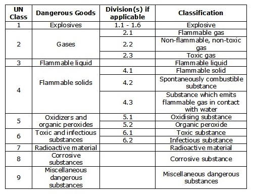
Classes of Dangerous Cargo are:
Class 1: Explosives
Division 1.1: substances and articles which have a mass explosion hazard
Division 1.2: substances and articles which have a projection hazard but not a mass explosion hazard
Division 1.3: substances and articles which have a fire hazard and either a minor blast hazard or a minor projection hazard or both, but not a mass explosion hazard
Division 1.4: substances and articles which present no significant hazard
Division 1.5: very insensitive substances which have a mass explosion hazard
Division 1.6: extremely insensitive articles which do not have a mass explosion hazard.
Class 2: Gases
Class 2.1: flammable gases
Class 2.2: non-flammable, non-toxic gases
Class 2.3: toxic gases
Class 3: Flammable liquids
Class 4: Flammable solids; substances liable to spontaneous combustion; substances which, in contact with water, emit flammable gases
Class 4.1: flammable solids, self-reactive substances and solid desensitized explosives
Class 4.2: substances liable to spontaneous combustion
Class 4.3: substances which, in contact with water, emit flammable gases.
Class 5: Oxidizing substances and organic peroxides
Class 5.1: oxidizing substances
Class 5.2: organic peroxides
Class 6: Toxic and infectious substances
Class 6.1: toxic substances
Class 6.2: infectious substances
Class 7: Radioactive material
Class 8: Corrosive substances
Class 9: Miscellaneous dangerous substances and articles
The numerical order of the classes and divisions is not that of the degree of danger.
Class 10: Marine pollutants
Marine pollutants shall be classified in accordance with chapter 2.9.3 in IMDG Code.
IMDG Cargoes – Dangerous Goods Classes
The documents required for carriage of IMDG cargo are:-
Shipping declaration
Document of compliance
Dangerous goods manifest
Objective of IMDG Code:
Enhance the safe carriage of dangerous goods by all modes of transportation.
Facilitate free and unrestricted movement.
Bring worldwide uniformity in their carriage regulations.
Prevent injury to personnel.
Prevent damage to ship and her cargoes.
Regulate the carriage of marine pollutant so as to prevent damage to marin environment.
Shipper’s Declaration of Dangerous Goods:
The legislation requires a declaration from the consignor (shipper) stating that the goods declared are classified and packed correctly and also a declaration from the person packing the container that it has been done so correctly, these are Dangerous Goods Declaration and the Container Packing Certificate.
These declarations may be in any format, but must be in accordance with the regulations of the IMDG code, Chapter 5.4 refers (an example is given below) Often, the Dangerous Goods Declaration is combined with the Container Packing Certificate into one document, generally known as the Multimodal Dangerous Goods Form.
These documents can also known as Dangerous Goods Note (DGN), Dangerous Goods Declaration (DGD), Multimodal Dangerous Goods Form (MDGF), Shippers Declaration, and Dangerous Cargo Declaration (DCD)
The information required on the documents is as follows:
Shipper – full name and address
Consignee – full name and address
Description of goods in sequence
a) UN number (preceded by UN)
b) Proper Shipping Name including technical name (if required)
c) Primary IMO class, secondary, tertiary
d) Packing Group
Information which supplements the Proper Shipping Name in the dangerous goods description (If applicable)
Technical names for “n.o.s.” and other generic descriptions
Empty uncleaned packagings, bulk containers and tanks
Wastes
Elevated temperature substances
Marine Pollutants
Flashpoint
Mass kg gross/ net
In addition to the dangerous goods description the following information shall be included after the dangerous goods description on the dangerous goods transport document.
Total quantity of dangerous goods: – This includes the weight in Kilos of each substance, as well as the number and type of packaging.
Also to be included if applicable;
Limited quantities
Salvage packagings
Substances stabilized by temperature control
Control and Emergency temperature: ….° C
Aerosols – If the capacity of an aerosol is above 1000ml, this shall be declared.
Statement: “Dangerous goods being transported have been packed, labeled & declared in accordance with standard international shipping regulation & IMDG code”
Segregation of Dangerous Goods:
This section has tables for following:
Segregation for dangerous goods carried in packaged form: this is given in the form of a table. Stating the type of segregation required between classes of cargo, excluding class 1, which has an altogether separate table. The terms used for segregation are:
Away from: Effectively segregated so that the incompatible goods cannot interact dangerously in the event of an accident but may be transported in the same compartment or hold or on deck, provided a minimum horizontal separation of 3 m, projected vertically, is obtained.
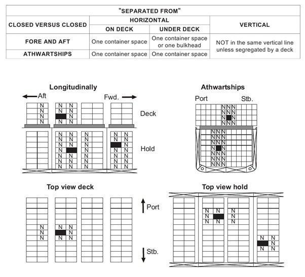
Separated from: In different compartments or holds when stowed under deck. Provided the intervening deck is resistant to fire and liquid, a vertical separation, i.e., in different compartments, may be accepted as equivalent to this segregation. For on deck stowage, this segregation means a separation by a distance of at least 6 m horizontally.
Separated by a complete compartment or hold from: Either a vertical or a horizontal separation. If the intervening decks are not resistant to fire and liquid, then only a longitudinal separation, i.e., by an intervening complete compartment or hold, is acceptable. For on deck stowage, this segregation means a separation by a distance of at least 12 m horizontally. The same distance has to be applied if one package is stowed on deck, and the other one in an upper compartment.
Note: One of the two decks must be resistant to fire and to liquid.
Separated longitudinally by an intervening complete compartment or hold from: Vertical separation alone does not meet this requirement. Between a package under deck and one on deck, a minimum distance of 24 m, including a complete compartment, must be maintained longitudinally. For on deck stowage, this segregation means a separation by a distance of at least 24 m longitudinally.
Legend
Reference package. . . . . . . . . .
Package containing incompatible goods . . .
Deck resistant to fire and liquid. .
Note: Vertical lines represent transverse watertight bulkheads between cargo spaces.
For containers the table is the same as above but the meaning of the above segregation terms is different.
For hatch coverless type container vessel, the table is again the same but the meanings of the above segregation terms are different.
Separate table for segregation between cargo in bulk and cargo in packaged form.
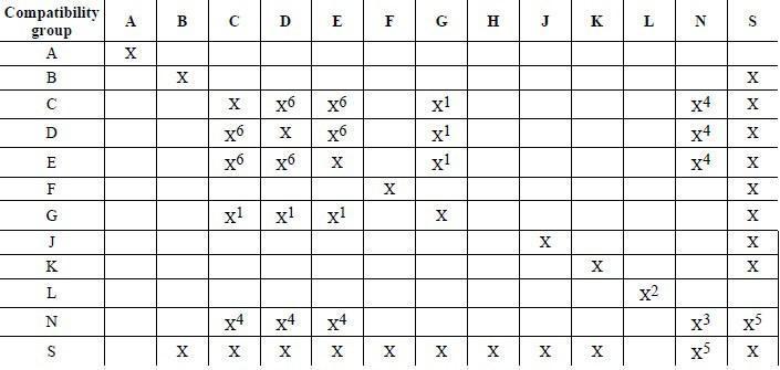
Segregation table for class 1 cargo which is by compatibility codes. Which are A to L, N and S.
Precautions while Loading/ Carrying/ Discharging Dangerous Goods:
“No Smoking” signs to be put up & strictly enforced.
“No naked lights” permitted on the deck or in the holds.
Fire hoses to be rigged, fire main charged & other fire fighting apparatus kept in a constant state of readiness.
Spark arresters to be fitted over the funnel, galley – exhausts & hold ventilators.
No hot work, chipping or painting to be in progress on deck to avoid creating sources of ignition.
Flashlights, walkie-talkies etc. to be intrinsically safe.
No oily waste, wood, rope, gunny, etc, to be left in hold or on deck where it can catch fire by spontaneous heating.
Fire patrol & gangway watches to be maintained.
Refer to the IMDG Code & findout the particulars for the cargo to be loaded with regards to hazards (compatibility, stowage, segregation)
The appropriate international code of signals by day & by night is to be displayed.
No bunkering operation is to be carried out during loading or discharging.
Wireless transmission should not be done of voltage exceeding 50 volts.
Radar should not be operated during loading or discharge.
Forklifts should not be used in the vicinity of dangerous goods.
Loading is to be suspended if inclement weather threatens.
Defective packages should not be accident.
Port regulation is to be complied.
Explosive must be stowed in a magazine, which is a woodlined compartment, sometimes specially constructed to stow explosives safely.
No electric cables should pass through the magazine, if this is unavoidable, the cable should be sheathed by an approved, sealed, non combustible barrier & tested before loading.
Explosive are unstable when wet & should be stowed in a cool, dry, well ventilated space away from hot bulkhead or decks.
Electrical fittings must be disconnected in compartments containing dangerous goods.
Ventilation fans to the space must be flame-proof, if not disconnected.
Explosives must be stowed away from living quarters.
Masts must be fitted with an efficient lightning conductor as lightning presents a grave danger.
Precautions to be taken if Cargo has to be carried under Fumigation:
Cargo transport units loaded without ventilation after fumigation (fumigation in transit):- When a cargo transport unit under fumigation is taken on board ship without preliminary ventilation, it shall be transported as FUMIGATED CARGO TRANSPORT UNIT, UN 3359, Class 9 in accordance with the provisions of the IMDG Code.
The following special precautions apply to ship-side operations:
A fumigated cargo transport unit shall not be allowed on board until a sufficient period has elapsed to attain a reasonable uniform gas concentration throughout the cargo in it. Because of variations due to types and amounts of fumigants and commodities and temperature levels, the period between fumigant application and loading of the fumigated unit on board the ship shall be determined by the competent authority. Twenty-four hours is normally sufficient for this purpose. Before loading the cargo transport unit should be checked for leaks and any leakage sealed.
The master shall be informed prior to loading of fumigated cargo transport units under fumigation. These shall be identified with the warning mark, incorporating the fumigant name and the date and time of fumigation.
The special list/manifest/stowage plan shall identify the fumigated cargo transport units and indicate their stowage location on board. The transport document for fumigated cargo transport units shall indicate the date of fumigation and the type and amount of fumigant used.
Stowage category B has been assigned to UN 3359; however, on deck stowage is preferred. In addition, it shall be stowed clear of living quarters and should be 6 m away from vent intakes.
If stowed under deck, the cargo space should be equipped with mechanical ventilation sufficient to prevent the build-up of fumigant concentrations above the toxicity levels (threshold limits) set out by competent authorities. The threshold limit for occupational exposure to the fumigant can be found on the Safety Data Sheet if available. The ventilation rate of the mechanical ventilation system should be at least two air changes per hour, based on the empty cargo space.
If stowed under deck, equipment suitable for detecting the fumigant gas or gases used shall be carried on the ship, with instructions for its use.
Before a fumigated cargo transport unit is loaded to a ship under deck, special precautions are necessary. This should include the following:
At least an officer and one other are to receive appropriate training and will be designated as the trained representatives of the master. The master, through his representative, is responsible for ensuring safe conditions in the occupied spaces of the ship; and
The trained representatives should brief the crew before the fumigated cargo transport unit is loaded.
Most fumigant gases are heavier than air so care should be taken in the holds particularly when working on the tank tops.
The trained representatives of the master should be provided, and be familiar, with:
The information in the relevant Safety Data Sheet (SDS), if available; and
The recommendations of the fumigant manufacturer concerning methods of detection of the fumigant in air, its behaviour and hazards properties, symptoms of poisoning, relevant first aid and special medical treatment and emergency procedures.
The ship should carry:
appropriate gas-detection equipment for the fumigant concerned, together with instructions for its use when the fumigated cargo transport unit is stowed under deck;
instructions on disposal of residual fumigant material; and
emergency response information regarding UN 3359 such as a copy of the latest version of the Medical First Aid Guide for Use in Accidents Involving Dangerous Goods (MFAG).
In addition, the ship should carry at least four sets of appropriate respiratory protective equipment, and, when the fumigated cargo transport unit is stowed on deck, appropriate gas detection equipment for the fumigant concerned, together with instructions for its use.
Prior to the arrival of the ship, generally not less than 24 hours in advance, the master should inform the appropriate authorities of the country of destination and ports of call that fumigation in transit is being carried out. The information should include the type of fumigant used, the date of fumigation and cargo spaces carrying fumigated cargo transport units.
Dangerous Goods Manifest:-
The carrier, its agents, and any person designated for this purpose by the carrier or agents must prepare a dangerous cargo manifest, list, or stowage plan. This document may not include a material that is not subject to the requirements of the Hazardous Material Regulations or the IMDG Code. This document must be kept on or near the vessel’s bridge, except when the vessel is docked in a United States port. When the vessel is docked in a United States port, this document may be kept in the vessel’s cargo office or another location designated by the master of the vessel provided that a sign is placed beside the designated holder on or near the vessel’s bridge indicating the location of the dangerous cargo manifest, list, or stowage plan. This document must always be in a location that is readily accessible to emergency response and enforcement personnel. It must contain the following information:
(1) Name of vessel and official number. (If the vessel has no official number, the international radio call sign must be substituted.);
(2) Nationality of vessel;
(3) Shipping name and identification number of each hazardous material on board as listed in as listed in the IMDG Code and an emergency response telephone number.
(4) The number and description of packages (barrels, drums, cylinders, boxes, etc.) and gross weight for each type of package;
(5) Classification of the hazardous material in accordance with either:
(i) The Hazardous Materials Table, or
(ii) The IMDG Code.
(6) Any additional description required.
(7) Stowage location of the hazardous material on board the vessel.
(8) In the case of a vessel used for the storage of explosives or other hazardous materials, the following additional information is required:
(iv) Name and address of the owner of the cargo; and (v) A complete record, by time intervals of one week, of all receipts and disbursements of hazardous materials. The name and address of the consignor must be shown against all receipts and the name and address of the consignee against all deliveries.
(b) The hazardous material information on the dangerous cargo manifest must be the same as the information furnished by the shipper on the shipping order or other shipping paper, except that the IMO “correct technical name” and the IMO class may be indicated on the manifest as provided in paragraphs (a)(3) and (a)(5) of this section. The person who supervises the preparation of the manifest, list, or stowage plan shall ensure that the information is correctly transcribed, and shall certify to the truth and accuracy of this information to the best of his knowledge and belief by his signature and notation of the date prepared.
(c) The carrier and its agents shall insure that the master, or a licensed deck officer designated by the master and attached to the vessel, or in the case of a barge, the person in charge of the barge, acknowledges the correctness of the dangerous cargo manifest, list or stowage plan by his signature.
(d) For barges, manned or unmanned, the requirements of this section apply except for the following:
(1) In the case of a manned barge, the person in charge of the barge shall prepare the dangerous cargo manifest.
(2) In the case of an unmanned barge, the person responsible for loading the barge is responsible for the preparation of a dangerous cargo manifest, list, or stowage plan and must designate an individual for that purpose.
(3) For all barges, manned or unmanned, the dangerous cargo manifest must be on board the barge in a readily accessible location and a copy must be furnished to the person in charge of the towing vessel.
(e) Each carrier who transports or stores hazardous materials on a vessel shall retain a copy of the dangerous cargo manifest, list, or stowage plan for at least one year, and shall make that document available for inspection.
IMDG code: Excepted Quantities:
The excepted quantity is the maximum quantity per inner and outer packaging for transporting dangerous goods as excepted quantities. The quantity limit can be found in the column 7b of the Dangerous Goods List. 7b does not directly list the max quantity per inner and outer packaging. Instead, 7b gives various E codes (E0~E5).
IMDG code: Limited Quantities:
Limited quantities –
The limited quantity is the maximum quantity per inner packaging or article for transporting dangerous goods as limited quantities. It can be found in the column 7a of Dangerous Goods List. In the example below, the limited quantity for antimony compounds is 5kg per inner packaging.
IMDG code: Compatibility Group:
Compatibility group refers to a designated alphabetical letter used to categorize different types of Class 1 explosive substances and articles for purposes of safe stowage and segregation.
Document of Compliance (SOLAS II-2/54.3) pertaining to dangerous goods:
The administration shall provide the ship with an appropriate document of evident of compliance of construction & equipment with the requirements of this regulation, Reg.19 of SOLAS 54, Chp. II-2, as amended.
Certification for dangerous goods, except solid dangerous goods in bulk is not required for those cargoes specified as class 6.2 & 7 as defined in reg. VII/2 and dangerous goods in limited quantities.
The document of compliance shall also contain information indicating class wire allowable locations for stowage of dangerous goods in packaged form onboard.
SOLAS Chapter VII – Part A – Carriage of Dangerous Goods in Packaged Form:-
Application:-
Unless expressly provided otherwise, this part applies to the carriage of dangerous goods in packaged form in all ships to which the present regulation apply and to cargo ships of less then 500 GrT.
The provisions of this port do not apply to ship’s stores & equipments.
The carriage of dangerous goods in packaged form is prohibited, except in accordance of this chapter.
To supplement the provisions of this part, each contracting government shall issue detailed instructions on EMS & Medical First Aid to be provided, relevant to incidents involving Dangerous Goods in Packaged form, taking into account the guidelines, viz EMS Guide & MFAG Guide, developed by the organisation.
Requirements for Carriage of Dangerous Goods:-
The carriage of Dangerous Goods in packaged form shall be in compliance with the relevant provisions of the IMDG code.
Documentation:-
In all documents relating to the carriage of Dangerous Goods in packaged form by sea, the Proper Shipping Name shall be used (trade name, alone shall not be used) and the correct description given in accordance with the classification set out in the IMDG code.
The transport documents prepared by the shipper shall be accompanied with a signed certificate or a declaration, stating that the consignment offered for shipment is properly packed, marked & labelled or placarded as appropriate and in proper condition for carriage.
The person responsible for packing / loading of dangerous goods in CTU shall provide a singed container / vehicle packing certificate stating that the cargo in the unit has been properly packed and secured and that all applicable transport requirements have been met.
Where there is due cause to suspect that a Cargo Transport Unit (CTU) in which the Dangerous Goods are packed in compliance with the requirements of par (2) & (3) above such CTU shall not be accepted the carriage.
Each ship carrying Dangerous Goods in packaged form shall have a special list or manifest setting forth, in accordance to the locations there of. A copy of these documents, shall be made available before departure to the person or organisations designated by the port state authority.
Cargo Securing Manual:-
Cargo, Cargo Units & Cargo Transport Unit’s shall be loaded, stowed & secured throughout the voyage in accordance with the Cargo Securing Manual approved by the Administration. (more info)
Reporting of Incidents involving Dangerous Goods:-
When an incident takes place involving the loss or likely loss overboard of dangerous goods in packaged form into the sea, the master or other person having charge of the ship shall report the particulars of such an incident without delay and to the fullest extent to nearest coastal state.
The report shall be drawn up based on general principles & guidelines developed by the organisation.
M.S. Act Sec.331:-
The Central Government may make rules for regulating in the interest of safety, the carriage of dangerous goods in ships.
In particular and without prejudice to the generally of the foregoing power, such rules may provide for the classification, packing, labelling & marking of such goods (whether with or w/o other cargo), including the plan for stowing, the fixing of the maximum quantity of any such class of goods which may be carried in different ships or classes of ships.
The owner, master or agent of a ship carrying or intending t carry any dangerous goods as cargo and about to make a voyage from a portion. India, shall furnish in advance the prescribed particulars of the ship and the cargo to such authority as may be prescribed for the purpose.
A surveyor may inspect the ship for the purpose of securing that any rules under this section are complied with.
If any rules made in pursuance of the section is not complied with in relation to any ship, the ship shall be deemed for the purpose of this part to be an unsafe ships.
This section shall apply in the same manner as it applies to Indian Ships, to ships other than Indian Ships while they are within any part in India or are embarking or disembarking passengers or are loading or discharging cargo or fuel within Indian Jurisdiction.
Explanation:-
Expression “Dangerous Goods” means goods which by reason of the nature, quantity or mode of stowage are either singly or collectively liable to endanger the life or health of persons or near the ship or to imperil the ship and includes all substances within the meaning of expression, explosion as defined in the Indian Explosive Act. 1884, and any other goods which the Central Government may be notification in the official Gazette, specify as dangerous goods.
Types of Magazines for Carriage of Explosives:
Magazine Stowage for Explosives:
Magazine means a closed cargo transport unit or a compartment in the ship designed to protect certain goods of class 1 from damage by other cargo during loading & unloading and adverse weather conditions when in transit & to prevent unauthorised access.
The stowage of explosive substances and certain articles is subjected to varying levels of containment when stowed below deck are primarily defined as Magazine Stowage Type “A”, “C” & “Special Stowage.
Magazine Stowage Type “A”:
Stowage applies to those substances which shall be kept clear of steel works.
The innerside & floors of compartment are close boarded with wood (covered with wood).
The shipside should also be free of rust and should be covered with battens placed not more than 150mm apart.
Roof or deck-head clean and free of rust. However, it need not be battened.
The top of the stow atleast 300 mm clear of deck-head.
Guards against friction between any spilled contents & packages.
Packaging requiring magazine, Type “A” stowage shall have no exposed external parts made of ferrous metal or aluminium alloy.
One or more doorway, atleast 1.2m wide, should be fitted facing the hatchway.
Magazine Stowage Type “C”:
Means a closed cargo transport unit positioned as nearly as practicable to the C/L of the ship.
It shall not be positioned closer to the ship’s side than a distance equal to one-eight of the beam or 2.4m whichever is lesser.
Special Stowage:
Goods of Class 1 (Explosives), allocated to this category shall be stowed as far as practicable from living quarters.
Closed CTU’s used for goods of this category shall not be positioned closer to the ships side then a distance equal to 1/8 of beam or 2.4m whichever is lesser.
This stowage is allocated to certain articles of which the principal hazard is that of fire accompanied by dense smoke & tear. (Compatibility group G, H or K) and also substance presenting special risk (compatibility group L).
A steel CTU which prevent leakage of contents shall be used for this purpose.
Goods of only one compatibility group shall be stowed in any one compartment.
When separate compartments are not available, the competent authority may allow goods in compatibility group G & H to be stowed in the same compartment not less than 3m apart, stowed in separate steel magazines.
IMDG Code: Labels / Placards:
The IMDG Code recommends a system based on labels and placards designed especially so that all who work close to this type of cargo will be able to recognize, preferably at first sight, the nature of the risks entailed by these substances, whatever their packaging might be.
Labels: –
The IMDG Code states that all packaging, packages and drums carrying dangerous goods must be labelled. The labels are in the shape of a rhombus in white, orange, blue, green or red, or a combination of these colours. Symbols illustrating the danger of the class are also required. In general, each label is divided into two parts, the bottom half and the top half. The top half is for the symbol of the class of the good(s), and the lower half is for the text, class or division number. The minimum dimensions of labels are 10 cm x 10 cm. Labels must be firmly adhered to and placed on the package so that it can easily be seen. The quality of the labels must be such so they do not deteriorate outdoors and remain unaltered during the complete transport period and at least three months in the sea. Due to the fact that dangerous goods can pose more than one risk, it is also necessary to use “secondary risk labels”. These labels are the same as the ones showing the primary risk, regarding their colour, shape and symbols. Even though the IMDG Code says nothing to this effect, in some countries the class number is only indicated in the primary risk label, and that the secondary risk label does not include the class number. This is an effective way to distinguish between both.
Placards: –
The IMDG Code determines that all “cargo transport units” containing dangerous goods must be placarded. In this context, cargo transport units are containers, containers for liquids, tank vehicles, vehicles transporting goods by land, railway wagons with water tanks, good tanks destined for intermodal transport. Placards have the same shape, colours and symbols as the labels, but their dimension is 25 x 25 cm. Containers carrying more than 4000 kilograms of dangerous goods, and all tanks for liquids and gases must have the “United Nations number”. The UN number has four digits and is the number assigned by the United Nations to all goods identified and classified as dangerous.
Containers carrying dangerous goods must display at least one placard on each side and one on each end of the unit (this is to say, on its four sides).
Rail wagons must be placarded on at least both sides.
Freight containers, semi-trailers and portable tanks must be placarded on all four sides.
Road vehicles must display appropriate placards on both sides as well as the rear.
Hazardous Materials Warning Placards:-
CLASS 1 Explosives
*Enter Division Number 1.1, 1.2, 1.3 and compatibility group letter, when required. Placard any quantity.
CLASS 1.4 Explosives *Enter compatibility group letter, when required. Placard 454 kg (1,001lbs) or more.
CLASS 1.5 Explosives *Enter compatibility group letter, when required. Placard 454 kg (1,001lbs) or more.
CLASS 1.6 Explosives *Enter compatibility group letter, when required. Placard 454 kg (1,001lbs) or more.
CLASS 2 OXYGEN Placard 454 kg (1,001lbs) or more, gross weight of either compressed gas or refrigerated liquid.
CLASS 2 FLAMMABLE GAS Placard 454 kg (1,001lbs) or more.
CLASS 2 NON-FLAMMABLE GAS Placard 454 kg (1,001lbs) or more, gross weight.
CLASS 2 POISON GAS Placard any quantity 2.3 material.
CLASS 3 FLAMMABLE Placard 454 kg (1,001lbs) or more.
CLASS 3 GASOLINE May be used in the place of FLAMMABLE on a placard displayed on a cargo tank or a portable tank being used to transport gasoline by highway.
CLASS 3 COMBUSTIBLE Placard a combustible liquid when transported in bulk. see §172.504(f)(2) for use of FLAMMABLE placard in place of COMBUSTIBLE placard.
CLASS 3 FUEL OIL Placard 454 kg (1,001lbs) or more.
CLASS 4 FLAMMABLE SOLID Placard 454 kg (1,001lbs) or more.
CLASS 4 SPONTANEOUSLY COMBUSTIBLE Placard 454 kg (1,001lbs) or more.
CLASS 4 DANGEROUS WHEN WET Placard any quantity of Division 4.3 material.
CLASS 5 OXIDIZER Placard 454 kg (1,001lbs) or more.
CLASS 5 ORGANIC PEROXIDE Placard 454 kg (1,001lbs) or more.
CLASS 6 KEEP AWAY FROM FOOD Placard 454 kg (1,001lbs) or more.
CLASS 6 POISON Placard any quantity of 6.1, PGI, inhalation hazard only. Placard 454 kg (1,001 lbs) or more of PGI or II, other than PGI inhalation hazard.
CLASS 7 RADIOACTIVE Placard any quantity of packages bearing the RADIOACTIVE III label. Certain low specific activity radioactive materials in “exclusive use” will not bear the label, but RADIOACTIVE placard is required.
CLASS 8 CORROSIVE Placard 454 kg (1,001lbs) or more.
CLASS 9 miscellaneous Not required for domestic transportation. Placard 454 kg (1,000 lbs) or more gross weight of a material which presents a hazard during transport, but is not included in any other hazard class.
DANGEROUS
Placard 454 kg (1,001 lbs) gross weight of two or more categories of hazardous materials listed in Table 2. A freight container, unit load device, motor vehicle, or rail car which contain non-bulk packagings with two or more categories of hazardous materials that require placards specified in Table 2 may be placarded with a DANGEROUS placard instead of the separate placarding specified for each of the materials in table 2. However, when 2,268 kg (5,000 lbs) or more of one category of material is loaded at one facility, the placard specified in Table 2 must be applied.
SUBSIDIARY RISK PLACARD Class numbers do not appear on subsidiary risk placard.
RAIL Placard empty tank cars for resident of material last contained.
Required background for placard on rail shipments of certain explosives and poisons. Also required for highway route controlled quantities of radioactive materials. (see §172.507 and 172.510).
IMDG – Hazardous Materials Warning Placards – UN or NA identification numbers
IMDG code Vol1 chapter 7.2 on Segregation gives all the information on segregation.
Separated longitudinally by an intervening complete compartment or hold from: – Vertical separation alone does not meet this requirement. Between a package under deck and one on deck, a minimum distance of 24 metres, including a complete compartment, must be maintained longitudinally. For on deck stowage, this segregation means a separation by a distance of at least 24 metres longitudinally.
Hazards associated with IMDG cargo & Precautions to be taken while Loading Dangerous Goods in Packaged Form:
Dangerous goods are assigned to different classes depending on their predominant hazard. The UN classifies dangerous goods in the following classes and, where applicable, divisions:
IMDG – UN assigned classes of Dangerous Goods
PRECAUTIONS WHEN LOADING / UNLOADING DANGEROUS GOODS:-
Documentation in order (shipper’s declaration, container packing certificate, emergency information) emergency information).
All cargo operations supported by a responsible officer who should be in possession of operational and emergency information (including stability information)
No intoxicated person to be allowed charge of operation,
No unauthorized person allowed in vicinity of cargo being handled,
Compartment dry and suitable for cargo,
Cargo handling equipment checked before use,
No cargo handling under adverse weather conditions,
Packaging and segregation as per IMDG code,
All cargo properly labelled, no labels defaced or removed,
Cargo handled carefully, handling kept to minimum,
Tanks not overfilled,
Port authority informed,
Fire wires rigged as necessary,
Emergency equipment available for fire / spillage,
Suitable precautions against fire and explosion,
Packages to be stowed as planned in accordance with the IMDG code,
Cargo space to be properly ventilated,
‘B’ flag displayed,
There is a safe access to the packages, so that in case of fire they can be removed,
Electrical fitting in good condition.
The package is properly labelled / marked and placarded.
If cargo in drums, they should be stowed vertically,
The cargo should be placed in such a manner that there is safe and clear access to all LSA / FFA,
Packages should be stowed away from sunlight or other heat sources,
No cargo should be stowed on top of portable tanks,
Dg’s with give of vapour to be stowed on deck or in mechanically ventilated spaces,
Cargo securing manual to be complied with Segregation as per the IMDG code.
Duties of Carrier & Shipper with respect to carriage of dangerous goods as per IMDG Code:
Under the IMDG (International Maritime Dangerous Goods) Code It is the onus of the shipper to determine the class of the substances according to provided criteria:-
Stowage and segregation of dangerous goods:- Stowing and lashing the cargo are part of the operation of loading. It refers to the placing of the goods in a ship’s spot or a container. if there is an express contract or custom, stowage is done by the shipper. Chapter 7 of the IMDG Code contains detailed provisions regarding stowage and segregation of incompatible dangerous goods. Stuffing and sealing of the containers, is the responsibility of the shipper.
Common Law:-
To Pay Freight:- It is the shipper’s obligation to pay the freight agreed upon. The carrier has a lien on the cargo for unpaid freight.
Not to ship dangerous goods without warning:- The shipper is responsible for notifying the carrier of any dangerous goods and is liable for failing to do so.
To share in general average:- If a general average situation occurs the owner of the saved cargo and the carrier are obliged to jointly compensate the owner of the jettisoned cargo.
Explosives which may be Carried on Passenger Ships:
No other explosives may be transported on passenger ships except any one of the following:
Explosive articles for life-saving purposes listed in the Dangerous Goods List, if the total net explosives mass of such articles does not exceed 50 kg per ship; or
Goods in compatibility groups C, D and E, if the net explosives mass does not exceed 10 kg per ship; or
Articles in compatibility group G other than those requiring special stowage, if the total net explosives mass does not exceed 10 kg per ship; or
Articles in compatibility group B, if the total net explosives mass does not exceed 10 kg per ship.
SOURCE:- IMDG Code 7.1.7.5.2 Explosives in division 1.4, compatibility group S, may be transported in any amount on passenger ships.
Measures to be taken to Ensure a Safe Stowage and Carriage of Explosives:
Stowage of dangerous goods on board container ships are decided by two factors, Document of Compliance and IMDG Code. IMDG Code sets forth the Stowage and Segregation Rules which is executed on each vessel according to the Document of Compliance issued to her. Document of Compliance is issued to a vessel if it meets the requirements of SOLAS Regulation II-2/19, Construction – Fire protection, fire detection and fire extinction (Carriage of Dangerous Goods).
The Document of Compliance certifies that the construction and equipment of the mentioned ship have been found to comply with the provisions of regulation II-2/19 of the International Convention for the Safety of Life at Sea, 1974, as amended; and that the ship is suitable for the carriage of those classes of dangerous goods as specified in the appendix thereto, subject to any provisions in the International Maritime Dangerous Goods (IMDG) Code and the International Maritime Solid Bulk Cargoes (IMSBC) Code for individual substances, materials or articles also being complied with.
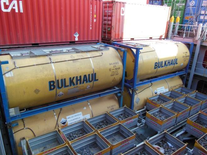
ISO Tanks loaded on Vessel:
In this document the under deck spaces and on deck spaces are marked separately for carriage of Packaged Dangerous Goods, Bulk Goods and what is not permitted.
Validity of the document of compliance will not exceed 5 years and will not be extended beyond the expiry date of the valid Cargo Ship Safety Construction Certificate issued to the ship concerned under the provisions of SOLAS regulation I/12. See Maritime Safety Committee Circular MSC.1/Circ.1266 for full details.
IMDG Code stowage and Segregation rules for dangerous goods vessels are categorized into two types, Cargo Ships and Passenger Ships. This categorization further divides cargo ships and passenger ships for carriage of Class 1, Explosives, and Classes 2 to 9. The differentiation is for Class 1, Explosives, Cargo ships (up to 12 passengers) and Passenger ships. For Classes 2-9 Cargo ships or passenger ships carrying a number of passengers limited to not more than 25 or to 1 passenger per 3 m of overall length, whichever is the greater number and Other passenger ships in which the limiting number of passengers transported is exceeded.
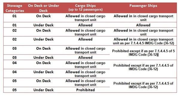
Stowage categories for Explosives (Class 1) – IMDG Code 36-12
For other than class 1 (Explosives) each dangerous goods listed in IMDG Code 36th Amendment, Dangerous Goods List column 16 specifies stowage requirement. This is indicated by Category A, B, C, D or E.
On Deck only stowage is always prescribed for cases where:
Constant supervision is required; or
Accessibility is particularly required; or
There is a substantial risk of formation of explosive gas mixtures, development of highly toxic vapours, or unobserved corrosion of the ship
Below dangerous goods when permitted to be loaded under deck by IMDG Code will additionally require mechanical ventilation for the cargo hold.
class 2.1;
class 3 with a flash point of less than 23°C c.c.;
class 4.3;
class 6.1 with a subsidiary risk of class 3;
class 8 with a subsidiary risk of class 3, and
dangerous goods to which a specific stowage requirement requiring mechanical ventilation in column 16 of the Dangerous Goods List is assigned.
Stowage Categories for Goods other than Class 1 (Explosives)
Stowage Categories for Goods other than Class 1 (Explosives)
For example, UN 2076 Class 6.1 CRESOLS, LIQUID, stowage category in column 16 of dangerous goods list is Category B. Substances, Materials or Articles assigned with stowage Category B can be loaded on deck or under deck on a cargo ship but on a passenger ship where limiting number of passengers are exceeded Category B must be loaded on deck only!
Segregation between containers carrying dangerous goods are different for containerships with closed cargo holds and hatchless containerships. Vertical and horizontal segregation, athwart ships, fore and aft is defined for Closed Versus Closed, Closed Versus Open and Open Versus Open.
Two closed containers requiring segregation “separated from” each other when loading vertically or horizontally they need to be segregated as shown.
Two closed containers requiring segregation “separated from” each other when loading vertically or horizontally
Two closed containers requiring segregation “separated from” each other when loading vertically or horizontally they need to be segregated as shown.
In IMDG Code 37th Amendment Stowage and Handling instructions are listed separately in column 16a in Dangerous Goods List with SW and H codes and column 16b lists out segregation codes, SG.
IMDG Code: Subsidiary Risk Label:
A subsidiary risk label shall also be affixed for any risk indicated by a class or division number in column 4 of the Dangerous Goods List of this Regulations;
when there is no indication of a subsidiary risk in column 4, the special provisions in column 6 may also require or exempt a subsidiary risk label;
Primary and subsidiary risk labels are required to be displayed next to each other;
An explosive subsidiary risk label, division 1.1 must be applied for type B self-reactive substances;
The class 5.2 label shall be affixed to packages containing organic peroxides classified as types B, C, D, E or F. In addition the following subsidiary risk labels shall be applied:
For organic peroxides type B, the explosive subsidiary risk label division 1.1;
If packing group I or II criteria of class 8 are met, the corrosive subsidiary risk label.
IMDG code: Stowage Category
Positioning of dangerous goods containers on board vessels are categorised by ‘stowage categories’ to ensure safety. Many points are considered by IMDG Code for safe carriage of dangerous goods by sea-going vessels.
On ships there are two different types of stowage (1) On deck and (2) Under Deck. When we look at a container vessel all those containers we see outside are stowed on deck. The containers stowed below the hatch covers are under-deck stowed units.
For other than class 1 ( explosives ) ships are divided into two groups for this purpose
1) cargo ships or passenger ships carrying a number of passengers limited to not more than 25 or to 1 passenger per 3 m of overall length, whichever is the greater number;
2) Other passenger ships in which the limiting number of passengers transported is exceeded.
For every dangerous goods listed in IMDG Code Dangerous Goods List column 16 specifies stowage requirement. This is indicated by Category A, B, C, D or E.
On Deck only stowage is always prescribed for cases where:
1. Constant supervision is required; or
2. Accessibility is particularly required; or
3. There is a substantial risk of formation of explosive gas mixtures, development of highly toxic vapours, or unobserved corrosion of the ship
Below is the entry for UN 2076 Class 6.1 CRESOLS, LIQUID, you can see in column 16 it is written Category B. Substances, Materials or Articles assigned with stowage Category B can be loaded on deck or under deck on a cargo ship but on a passenger ship where limiting number of passengers are exceeded Category B must be loaded on deck only.
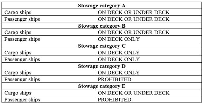
Stowage category A
Cargo ships or passenger ships carrying a number of Passengers limited to not more than 25 or to 1 passenger per 3 m of overall length, whichever is the greater number
ON DECK OR UNDER DECK
Other passenger ships in which the limiting number of passengers transported is exceeded
ON DECK OR UNDER DECK
Stowage category B
Cargo ships or passenger ships carrying a number of passengers limited to not more than 25 or to 1 passenger per 3 m of overall length, whichever is the greater number
ON DECK OR UNDER DECK
Other passenger ships in which the limiting number of passengers transported is exceeded
ON DECK ONLY
Stowage category C
Cargo ships or passenger ships carrying a number of passengers limited to not more than 25 or to 1 passenger per 3 m of overall length, whichever is the greater number
ON DECK ONLY
Other passenger ships in which the limiting number of passengers transported is exceeded
ON DECK ONLY
Stowage category D
Cargo ships or passenger ships carrying a number of passengers limited to not more than 25 or to 1 passenger per 3 m of overall length, whichever is the greater number
ON DECK ONLY
Other passenger ships in which the limiting number of passengers transported is exceeded
PROHIBITED
Stowage category E
Cargo ships or passenger ships carrying a number of passengers limited to not more than 25 or to 1 passenger per 3 m of overall length, whichever is the greater number
ON DECK OR UNDER DECK
Other passenger ships in which the limiting number of passengers transported is exceeded
PROHIBITED
IMDG Code: Compatibility between Explosives:
Class 1 – Explosives, are considered compatible with each other if storing them or transporting them together will not increase the probability of an accident or if there is an accident the magnitude of the effects. For this purpose explosives are divided into various compatibility groups. Each group is denoted by an alphabet from A to L, N and S (letter I is not used).
Divisions of Class 1 Explosives:-
Division 1.1: substances and articles which have a mass explosion hazard
Division 1.2: substances and articles which have a projection hazard but not a mass explosion hazard
Division 1.3: substances and articles which have a fire hazard and either a minor blast hazard or a minor projection hazard or both, but not a mass explosion hazard
Division 1.4: substances and articles which present no significant hazard
Division 1.5: very insensitive substances which have a mass explosion hazard
Division 1.6: extremely insensitive articles which do not have a mass explosion hazard
Compatibility Groups and Classification Codes:-
Compatibility group
Classification code
Description of substance or articles
A
1.1A
Primary explosive substance
B
1.1B1.2B1.4B
Article containing a primary explosive substance and not containing two or more effective protective features. Some articles, such as detonators for blasting, detonator assemblies for blasting and primers, cap-type, are included even though they do not contain primary explosives.
C
1.1C1.2C1.3C1.4C
Propellant explosive substance or other deflagrating explosive substance or article containing such explosive substance
D
1.1D1.2D1.4D1.5D
Secondary detonating explosive substance or black powder or article containing a secondary detonating explosive substance, in each case without means of initiation and without a propelling charge, or article containing a primary explosive substance and containing two or more effective protective features
E
1.1E1.2E1.4E
Article containing a secondary detonating explosive substance, without means of initiation, with a propelling charge (other than one containing a flammable liquid or gel or hypergolic liquids)
F
1.1F1.2F1.3F1.4F
Article containing a secondary detonating explosive substance with its own means of initiation, with a propelling charge (other than one containing a flammable liquid or gel or hypergolic liquids) or without a propelling charge
G
1.1G1.2G1.3G1.4G
Pyrotechnic substance, or article containing a pyrotechnic substance, or article containing both an explosive substance and an illuminating, incendiary, tear- or smoke-producing substance (other than a water-activated article or one containing whitephosphorus, phosphides, a pyrophoric substance, a flammable liquid or gel, or hypergolic liquids)
H
1.2H1.3H
Article containing both an explosive substance and white phosphorus
J
1.1J1.2J1.3J
Article containing both an explosive substance and a flammable liquid or gel
K
1.2K1.3K
Article containing both an explosive substance and a toxic chemical agent
L
1.1L1.2L1.3L
Explosive substance or article containing an explosive substance and presenting a special risk (such as due to water-activation or presence of hypergolic liquids, phosphides or a pyrophoric substance) and needing isolation of each type
N
1.6N
Articles containing only extremely insensitive detonating substances
S
1.4S
Substance or article so packaged or designed that any hazardous effects arising from accidental functioning are confined within the package unless the package has been degraded by fire, in which case all blast or projection effects are limited to the extent that they do not significantly hinder or prohibit fire fighting or other emergency response efforts in the immediate vicinity of the package
To check whether two explosives are compatible to be stored/transported together the transport regulation has a segregation table as shown below:-
Segregation Table for Explosives
Notes for above table:-
“X” indicates that goods of the corresponding compatibility groups may be stowed in the same compartment, magazine, cargo transport unit or vehicle.
Notes:
Explosive articles in compatibility group G (other than fireworks and those requiring special stowage) may be stowed with explosive articles of compatibility groups C, D and E provided no explosive substances are transported in the same compartment, magazine, cargo transport unit or vehicle.
A consignment of one type in compatibility group L shall only be stowed with a consignment of the same type within compatibility group L.
Different types of articles of Division 1.6, compatibility group N, may only be transported together when it is proven that there is no additional risk of sympathetic detonation between the articles. Otherwise they shall be treated as Division 1.1.
When articles of compatibility group N are transported with articles or substances of compatibility groups C, D or E, the goods of compatibility group N shall be treated as compatibility group D.
When articles of compatibility group N are transported together with articles or substances of compatibility group S, the entire load shall be treated as compatibility group N.
Any combination of articles in compatibility groups C, D and E shall be treated as compatibility group E. Any combination of substances in compatibility groups C and D shall be treated as the most appropriate compatibility group shown in 2.1.2.3 of IMDG Code, taking into account the predominant characteristics of the combined load. This overall classification code shall be displayed on any label or placard placed on a unit load or cargo transport unit as prescribed in 5.2.2.2.2 of IMDG Code.
Example compatibility check:-
With the above table let us check segregation requirement between below two explosives:-
UN 0161 Class 1.3C, POWDER, SMOKELESS
UN 0191 Class 1.4G, SIGNAL DEVICES, HAND
Segregation between compatibility letters C and G shows X1 and as per note x1 explosive articles of group G ( UN 0191 in this case) may be stowed with explosive articles of group C, D and E provided no explosive substances are loaded in the same container, UN 0161 is a substance hence cannot be loaded with UN 0191.
Applicable sections of IMDG Code for compatibility groups and segregation within explosives please refer to section 2.1.2 & 7.2.7
Stowage and Segregation of Dangerous Goods on General Cargo Ships:
Flammable gases or flammable liquids having a flashpoint of less than 23°C c.c, must be stowed on deck only, unless otherwise approved by the Administration and must be stowed at least 3 m from any potential source of ignition. Here possible sources of ignition may include open fires, machinery exhausts, galley uptakes, electrical outlets and electrical equipment including those on refrigerated or heated cargo transport units unless they are of certified safe type. For interpreting what is certified type, for cargo spaces, refer to SOLAS II:2/19.3.2 and for refrigerated or heated cargo transport units refer to Recommendation published by the international Electrotechnical Commission, in particular IEC 60079.
When explosives are loaded the compartments or holds and containers must be locked to pervert unauthorized access however when in emergency access to the locked places must be able to be gained without delay. If the cargo compartment floors are not fitted with closed boarded wood the loading/unloading equipment and process must ensure no sparks can occur. If the cargo gets wet all handling operations must be stopped unless specialist advise from shipper clears same. Personnel involved in cargo operations must be briefed prior work regarding the potential risks and necessary precaution. When explosives belonging to different compatibility groups are loaded they must be stowed not less than 6 meters from each other unless mixed loading is permitted between the involved compatibility groups as per section 7.2.7 of IMDG Code.
Non containerized flammable liquids packaged in plastics jerricans, plastics drums, plastics IBCs must always be stowed on deck. There are special requirements for stowage of FISHMEAL, UNSTABILIZED (UN 1374), FISHMEAL, STABILIZED (UN 2216, class 9) and KRILL MEAL (UN3497), SEED CAKE (UN 1386), AMMONIUM NITRATE BASED FERTILIZER, UN 2071 and certain other goods.
When feeds or other edible substances intended for consumption by humans or animals, foodstuff, is loaded it will require segregation ‘separated from’ toxic, radioactive and corrosive dangerous goods and Dangerous goods in other classes which has segregation reference in column 16 (16b in 37th amendment of IMDG Code).
There are four segregation rules for dangerous goods loaded in conventional way on board ships:
Away from: Effectively segregated so that the incompatible goods cannot interact dangerously in the event of an accident but may be transported in the same compartment or hold or on deck, provided a minimum horizontal separation of 3 metres, projected vertically is obtained.
Separated from: In different compartments or holds when stowed under deck. Provided the intervening deck is resistant to fire and liquid, a vertical separation, i.e. in different compartments, may be accepted as equivalent to this segregation. For on deck stowage, this segregation means a separation by a distance of at least 6 metres horizontally.
Separated by a complete compartment or hold from: Either a vertical or a horizontal separation. If the intervening decks are not resistant to fire and liquid, then only a longitudinal separation, i.e. by an intervening complete compartment or hold, is acceptable. For on deck stowage, this segregation means a separation by a distance of at least 12 metres horizontally. The same distance has to be applied if one package is stowed on deck, and the other one in an upper compartment.
Separated longitudinally by an intervening complete compartment or hold from: Vertical separation alone does not meet this requirement. Between a package under deck and one on deck, a minimum distance of 24 m, including a complete compartment, must be maintained longitudinally. For on deck stowage, this segregation means a separation by a distance of at least 24 metres longitudinally.
Segregation rules between containerized dangerous goods and those loaded in conventional ways are different. Dangerous goods stowed in the conventional way must be segregated from goods transported in closed containers in accordance with segregation provisions showed above except that for “away from” is required, no segregation between the packages and the closed cargo transport units is required; and where “separated from” is required, the segregation between the packages and the closed cargo transport units may be as for “away from”.
Segregation between Bulk dangerous goods and packaged dangerous goods must be in accordance with the table shown in section 7.6.3.5.2 of IMDG Code where all 4 segregation terms have different rules from those listed above.
For full details of the requirements of stowage and segregation of dangerous goods loaded on general cargo ships refer to chapter 7.6 of IMDG Code, individual entries in chapter 3.2 and IMSBC Code as applicable.
IMDG code:- Types of packaging group
Packing groups indicate the level of danger and thus assist in selecting correct type of package for Dangerous Goods
There are three packing groups assigned in IMDG Code as below
Packing group I: substances presenting high danger;
Packing group II: substances presenting medium danger; and
Packing group III: substances presenting low danger
Classes 1, 2, 5.2, 6.2 and 7, and self-reactive substances of class 4.1 are not assigned with packing groups
Let us look at the criteria for assigning packing groups for each of the classes.
Class 1: Explosives – No Packing group assigned
Class 2: Gases – No Packing group assigned
Class 3: Flammable liquids – Flammable liquids are grouped for packing purposes according to their flashpoint, their boiling
point, and their viscosity.
Below table shows the relationship between flashpoint and boiling point
Packing Group.
Flashpoint in °C closed cup (c.c.)
Initial boiling point in °C
I II III
– < 23 ≥ 23 to ≤ 60
≤ 35 > 35 > 35
Viscous substances such as paints, enamels, lacquers, varnishes, adhesives and polishes having a flash point of less than 23 °C may be placed in packing group III in conformity with the procedures prescribed in part III, chapter 32.3, of the United Nations Manual of Tests and Criteria on the basis of:
the viscosity, expressed as the flowtime in seconds;
the closed-cup flashpoint;
a solvent separation test.
Viscous flammable liquids such as paints, enamels, varnishes, adhesives and polishes with a flash point of less than 23 °C are included in packing group III provided that:
1) Less than 3% of the clear solvent layer separates in the solvent separation test;
2) The mixture or any separated solvent does not meet the criteria for class 6.1 or class 8.
3) The viscosity and flashpoint are in accordance with the following table:
Viscosity and Flashpoint of Flammable Liquids
4) The capacity of the receptacle used does not exceed 30 ℓ.
Substances classified as flammable liquids due to their being transported or offered for transport at elevated temperatures are included in packing group III.
Class 4.1 Flammable solids
Substance
Packing Group
Criteria
Readily combustible solids (other than metal powders)
II
If the burning time is less than 45 s and the flame passes the wetted zone
Powders of metal or metal alloys
II
if the zone of reaction spreads over the whole length of the sample in five minutes or less
Readily combustible solids (other than metal powders)
III
If the burning time is less than 45 s and the wetted zone stops the flame propagation for at leastfour minutes
Powders of metal
III
if the reaction spreadsover the whole length of the sample in more than five minutes but not more than ten minutes
Solids which may cause fire through friction
packing group shall be assigned by analogy with existing entries or in accordance with any appropriate special provision
Class 4.2 – Substances liable to spontaneous combustion
Class 4.2 comprises Pyrophoric substances & Self-heating substances
Substance
Packing Group
Criteria
Pyrophoric solids and liquids
I
Always Packing group I
Self-heating substances
II
which give a positive result in atest using a 25 mm sample cube at 140 °C
Self-heating substances
III
A positive result is obtained in a test using a 100 mm cube sample at 140 °C and a negative result is obtained in a test using a 25 mm cube sample at 140 °C and thesubstance is to be transported in packages with a volume of more than 3 m3;A positive result is obtained in a test using a 100 mm cube sample at 140 °C and a negative result is obtained in a test using a 25 mm cube sample at 140 °C, a positive result is obtained in a test using a 100 mm cube sample at 120 °C and the substance is to be transported in packages with a volume of more than 450 ℓ; A positive result is obtained in a test using a 100 mm cube sample at 140 °C and a negative result is obtained in a test using a 25 mm cube sample at 140 °C and a positive result is obtained in a test using a 100 mm cube sample at 100 °C.
Class 4.3 – Substances which, in contact with water, emit flammable gases
Packing Group
Criteria
I
any substance which reacts vigorously with water atambient temperatures and demonstrates generally a tendency for the gas produced to ignite spontaneously, or which reacts readily with water at ambient temperatures such that the rate of evolution of flammable gas is equal to or greater than 10 litres per kilogram of substance over any one minute.
II
any substance which reacts readily with water at ambienttemperatures such that the maximum rate of evolution of flammable gas is equal to or greater than 20 litres per kilogram of substance per hour, and which does not meet the criteria for packing group I.
III
any substance which reacts slowly with water at ambienttemperatures such that the maximum rate of evolution of flammable gas is equal to or greater than 1 litre per kilogram of substance per hour, and which does not meet the criteria forpacking groups I or II.
Class 5.1 – Oxidizing substances
Packing Group
Criteria
I
any substance which, in the 1:1 mixture (by mass) of substance andcellulose tested, spontaneously ignites; or the mean pressure rise time of a 1:1 mixture (by mass) of substance and cellulose is less than that of a 1:1 mixture (by mass) of 50% perchloric acid and cellulose;
II
Packing group II: any substance which, in the 1:1 mixture (by mass) of substance and cellulose tested, exhibits a mean pressure rise time less than or equal to the mean pressure rise time of a 1:1 mixture (by mass) of 40% aqueous sodium chlorate solutionand cellulose; and the criteria for packing group I are not met;
III
any substance which, in the 1:1 mixture (by mass) of substance and cellulose tested, exhibits a mean pressure rise time less than or equal to the mean pressure rise time of a 1:1 mixture (by mass) of 65% aqueous nitric acid and cellulose; and the criteria for packing groups I and II are not met;
Not Classified as 5.1
any substance which, in the 1:1 mixture (by mass) ofsubstance and cellulose tested, exhibits a pressure rise of less than 2070 kPa gauge; or exhibits a mean pressure rise time greater than the mean pressure rise time of a 1:1 mixture (by mass) of 65% aqueous nitric acid and cellulose.
Class 5.2 – Organic peroxides
No Packing group assigned
Class 6.1 – Toxic substances
Grouping criteria for administration through oral ingestion, dermal contact and inhalation of dusts and mists
IMDG – Class 6.1 – Toxic substances
Tear gas substances shall be included in packing group II even if their toxicity data correspond to packing group III values.
Liquids having toxic vapours:
Liquids having toxic vapours shall be assigned to the following packing groups, where “V” is the saturated vapour concentration in mℓ/m3 air at 20 °C and standard atmospheric pressure:
Packing group I: If V ≥ 10 LC50 and LC50 ≤ 1,000 mℓ/m3.
Packing group II: If V ≥ LC50 and LC50 ≤ 3,000 mℓ/m3, and do not meet the criteria for packing group I.
Packing group III: If V ≥ 5/1 LC50 and LC50 ≤ 5,000 mℓ/m3, and do not meet the criteria for packing groups I or II.
Tear gas substances shall be included in packing group II even if their toxicity data correspond to packing group III values.
Class 6.2 – Infectious substances
No Packing group assigned
Class 7 – Radioactive material
No Packing group assigned
Class 8 – Corrosive substances
Packing Group
Criteria
I
substances that cause full thickness destruction of intactskin tissue within an observation period of up to 60 minutes starting after an exposure time of 3 minutes or less
II
substances that cause full thickness destruction of intactskin tissue within an observation period of up to 14 days starting after an exposure time of more than 3 but not more than 60 minutes.
III
cause full thickness destruction of intact skin tissue within an observation period of up to 14 days starting after an exposure time of more than 60 minutes but not more than 4 hours; orare judged not to cause full thickness destruction of intact skin tissue but which exhibit a corrosion rate on either steel or aluminium surfaces exceeding 6.25 mm a year at a test temperature of 55 °C when tested on both materials.
Class 9 – Miscellaneous dangerous substances and articles and environmentally hazardous substances
Some are assigned to Packing Group II and some to III.
Test methods for determining packing groups for each class are published in United Nations Recommendations on the Transport of Dangerous Goods-Manual of Tests and Criteria, as amended.
Medical First Aid Guide (MFAG) Introduction & Contents:
The IMO/WHO/ILO Medical First Aid Guide for Use in Accidents involving Dangerous Goods (MFAG) refers to the substance, material and articles covered by the International Maritime Dangerous Goods Code (IMDG Code), and the materials covered by Appendix B of the Code of Safe Practice for Solid Bulk Cargoes (BC Code). It is intended to provide advice necessary for initial management of chemical poisoning and diagnosis within the limits of the facilities available at sea.
This Guide should be used in conjunction with the information provided in the IMDG Code, the BC Code, the Emergency Procedures for Ships Carrying Dangerous Goods (EmS), the International Code for the Construction and Equipment of Ships Carrying Dangerous Chemicals in Bulk (IBC Code), and the International Code for the Construction and Equipment of Ships Carrying Liquefied Gases in Bulk (IGC Code).
The MFAG itself gives general information about the particular toxic effects likely to be encountered. The treatment recommended in this Guide is specified in the appropriate tables and more comprehensive in the appropriate sections of the Appendices. However, differences exist between countries on certain types of treatment and where these differences occur they are indicated in the relevant national medical guide.
Treatments in this guide cater for the accidental human consequences of the carriage of dangerous goods at sea. Accidental ingestion of toxic substances during voyage is rare. The guide does not cover ingestion by intention.
Minor accidents involving chemicals do not usually cause severe effects provided that the appropriate first aid measures are taken. Although the number of reported serious accidents is small, accidents involving those chemicals which are toxic or corrosive may be dangerous, and must be regarded as being potentially serious until either the affected person has completely recovered, or medical advice to the contrary has been obtained.
Information on the treatment of illnesses which are of a general nature and not predominantly concerned with chemical poisoning may be found in the ILO/IMO/WHO International Medical Guide for Ships (IMGS).
CONTENTS:-
Table 1 – Rescue
Table 2 – Cpr (Cardio-Pulmonary Resuscitation)
Table 3 – Oxygen Administration and Controlled Ventilation
Table 4 – Chemical-Induced Disturbances Of Consciousness
Information on medical first aid to be provided in the incidents involving dangerous goods is enlisted in the MFAG Guide, which is provided as a supplement in the IMDG Code.
The advice given in the guide refers to the substances materials and articles covered by the IMDG code & materials covered by Appendix B of the IMSBC Code.
It is intended to provide advice necessary for chemical poisoning and diagnosis within the limits of facilities available at sea.
The treatment recommended in this guide is specified in the appropriate tables and more comprehensive in the appropriate section of Appendices.
For the convenience of user this guide is divided into three step approach procedure:
Step 1: Emergency Action & Diagnosys.
Step 2: Table – The tables give brief instruction for special circumstances.
Step 3: Appendices – The appendices provide comprehensive information a list of medicines / drugs and list of chemicals {in alphabetical & UN No. (Numerical)} in Appendix 15.
MFAG Table No.: The “Medical First Aid Guide for Use in Accidents involving Dangerous Goods” is a supplement to the IMDG code.
After looking up the MFAG Table No., see the table in the MFAG. It gives likely signs, symptoms, treatment and other advice as per the effect of goods under that table.
It suggests treatment in case of skin contact, eye contact inhalation and ingestion. The procedures for the treatment are also mentioned.
Preparations to be carried out prior to Loading Refrigerated Cargoes:
Reefer cargo should be loaded onboard only under the supervision of a recognized surveyor.
Cargo should not be allowed to wait for long time on the quay.
Hold should be pre-cooled to temp below the carriage temp.
Damp, wet and torn packages should be inspected if the cargo has deteriorated. If the cargo is fine then only it should be loaded after re-packing.
Contents of at least 5-10% cartons should be examined from each hold on a random basis.
Cartons with soft or dripping contents should bedocume rejected.
Refrigeration of holds should be turned on during long breaks and during meal breaks.
Once loaded, the cargo should be covered with tarpaulin.
During operations, the frost formed on top of the bripe pipes should be brushed carefully. It should not fall on top of the cargo.
In tropical climates avoid loading in the noon. Try to load cargo during night time.
Upon completion of loading, the reefer chamber must be closed air tight and cooling resumed immediately.
Principle & Working of different types of Refrigerated Cargo:-
1. Closed Reefer: This is a conventional type refrigerated container. It comes in one-piece with integral front wall and an all-electric automatic cooling and heating unit for ISO sea-going containers.
2. Modified/ Controlled Atmosphere (MA/CA) reefer containers: These type of insulated shipping containers maintain a constant atmosphere by replacing consumed oxygen using an air exchange system, keeping an ideal atmosphere in equilibrium with the product’s deterioration rate.
3. Automatic Fresh Air Management Containers: Popularly known by its acronym – AFAM reefer containers uses advanced technology to regulate the air combination by automatically adjusting the scale of fresh air exchange. It works similar to Controlled Atmosphere refrigerated container, controlling the composition of oxygen, carbon dioxide and others. The controls of the AFAM refrigerated containers can be adjusted to influence and extend the shelf lives of the cargo they carry.
Maintenance / Preparation of Cargo holds on board a Reefer vessel:
Depending upon the degree of littering, different methods of cleaning are to be used; For normal carton-packed cargoes with or without dunnage, it is usually enough to sweep the compartments. After meat and fish cargoes washing is almost always necessary. Sweeping must be carefully done and all dirt removed from the compartments. The holds should be swept as they are emptied and the dirt should be removed when the cargo has been discharged. If any cartons are broken and dunnage is spread all over the compartments, the situation is more complicated.
It has to be checked that goods from the cartons are not hidden anywhere on deck beams, in remote inaccessible corners or under the gratings. In these cases it is necessary to remove every piece of grating and sweep under it. Spot washes should be done, where cargo has come loose, been damaged or treaded down into gratings.
If the holds are badly littered, a careful washing has to be performed with a high pressure machine with a suitable washing detergent for the first cleaning, where after rinsing must be done carefully. If necessary, it must be deodorised using ozone, sodium bicarbonate or patent deodorisers but strong disinfectants not be used. The high pressure jet should not be applied at right angles to clean the surface but diagonally to the surface so that the jets cut away the dirt from the surface. The prescriptions from the supplier regarding the dosis of detergent must be carefully followed.
When cleaning it must be carefully checked that the whole compartments will be cleaned on the bulkheads as well as on and under decks with special care to deck beams and girders under deck on the upper side. The gratings should be cleaned properly including the bottom side as required.
The cooler rooms which contain the blowers and coils need to be also cleaned as and when required. The trays under the coolers must be kept clean. The purpose of these trays is to collect condensed water and melted ice and if necessary leakage from the coolers.
Scuppers are to be cleaned and brine traps checked, tested and refilled. Brine traps prevent warm air from entering the compartment and cold air from escaping; at the time same time allowing drainage of water.
Bilges and scupper drains should be clean and clear. Bilge pumping arrangements should be in working order and capable of pumping each bilge dry.
During cleaning it should be checked that the air flow channels are cleaned and when carrying out repairs to them special attention should be paid that the channels are not blocked.
Return air grids should be intact and clear. The air openings between the trays and the coolers are necessary in order to let the air pass. If this space is cluttered up, the air circulation will be throttled. Air ducts should be unobstructed. Fresh air flaps or valves should be free to move. The circulation and fresh air fans should be working satisfactorily.
The covers of the cargo hold lights should be intact. The hatch cover hydraulic system should be free of leakages. The cargo holds should be free of loose rust and paint chips.
The insulation and permanent dunnage is to be checked and repaired as required.
The hatch covers should be weathertight. All the gratings should be intact. Gratings should be free of moving and/ or tilting and/or sliding. The grating decks should have an even surface (flush). All spar deck beams should be intact and the spar decks should have an even surface (flush).
Pallet suitability:- The pallet side-boards should be intact. Instructions would be received for the use of pallet side-boards. Pallet problem areas should be identified and attended to. All pallet instructions should be removed, marked or made flush.
Signs:- Hygiene signs should be placed onboard before commencement of loading. The signs `NO SMOKING’ and `USE WALKING BOARDS’ should be painted in the hatch coamings.
Reefer Machinery:- Refrigeration system should be clear of leakages. The refrigeration machinery should be in working condition and adequate for the intended voyage and the electrical generating capacity should be sufficient for the intended voyage.
Reefer Monitoring Equipment:- Delivery and return air sensors should be calibrated by an ice bucket test regularly. USDA air and pulp sensors also should be calibrated by an ice bucket test. CO2 sensors should be operating properly. The humidity sensing and recording equipment should be working properly. Thermometers should be in position and ventilator plugs to the compartment fitted in place and tightly wedged.
All openings are to be sealed against entry of air.
Brine pipes are to be tested to ensure that they are not choked and that no leaks occur at the joints
Stores Stocks:- Sufficient cargo handling materials like Walking Boards, Slings, T Bars and Air bags should be available.
360 Quality certificate:- The vessel should have a valid 360 Quality certificate.
Indirect Method & Second Refrigerant (Brine Cooling) :
The primary refrigerant is used to cool a tank of brine and this cooled brine is then circulated through the compartment.
Brine is chosen because of its low freezing point, 20° to 30°C, depending on its concentration and composition.
The brine is passed through separate grids surrounding the same compartment.
If one grid is blocked or chocked, the brine supply can be increased to other grids so that cooling will not be affected.
Cooling is carried out by a combination of cold brine and cool air circulation.
Handling Reefer Cargo:
Frozen Cargo: Meat, Butter, Poultry and Fish. -8OC To -12OC
Chilled Cargo: Cheese, Eggs and Fresh Vegetables. -2OC To 6OC
Air Cooled Cargo: Fruits. 2OC to 12OC
Preparation of cargo hold:
The compartment must be clean, dry and free of any odour or taint,
Hold must be deodorised with mild agents (lime, ozone),
Bilges to be cleaned, dry, deodorised and suctions checked,
The insulation and permanent dunnage to be checked and repaired as necessary,
Scuppers to be cleaned,
Brine traps to be checked, tested and refilled,
Thermometers to be in position,
Ventilator plugs in position and tightly wedged,
Brine pipes to be tested to ensure they are not chocked and that no leaks occur at the joints.
Precooling of the compartment:
The compartment should be cooled down prior to loading to a temperature slightly lower than the transit temperature, Dunnage laid in the compartment should also be cooled down otherwise it will stain the cargo.
Precautions during loading:
Reefer cargo should be loaded onboard only under the supervision of a recognized surveyor,
Cargo should not be allowed to wait for long time on the quay,
Hold should be pre-cooled to temp below the carriage temp,
Damp, wet and torn packages should be inspected if the cargo has deteriorated. If the cargo is fine then only it should be loaded after re-packing,
Contents of at least 5-10% cartons should be examined from each hold on a random basis,
Cartons with soft or dripping contents should be rejected,
Refrigeration of holds should be turned on during long breaks and during meal breaks,
Once loaded, the cargo should be covered with tarpaulin,
During operations, the frost formed on top of the bripe pipes should be brushed carefully. It should not fall on top of the cargo.
In tropical climates avoid loading in the noon. Try to load cargo during night time,
Upon completion of loading, the reefer chamber must be closed air tight and cooling resumed immediately.
Precautions during Stowage:-
Cargo must be stowed in order to allow free circulation of air through and around the stow.
Laying of dunnage should be such that it does not obstruct designed air flow pattern in the compartment,
Sides and bulkheads should be fitted with vertical dunnage to keep cargo away from the structure,
Reefer chambers must be divided with air channels for each block not exceeding 3 mtrs. Channel must be atleast 10cms wide and aligned to face the cool air outlets. There should be an even gap of atleast 30 cms between the cargo top and the lowest part of the deckhead.
Dunnaging should be efficiently carried out so as to avoid stow collapsing into the air channels.
Each lot of cargo to be loaded according to the b/ls and separated by using colour tapes or net. Avoid loading cargo for more than 1 port in one chamber. Cargo once loaded should not be shifted. These measures will help prevent temperature fluctuations.
Refrigerated cargo is divided into 3 categories:
Frozen cargoes
Chilled cargoes
Cooled cargoes
Frozen Cargoes
e.g. Meat, butter, poultry and fish.
These cargoes are carried in a hard frozen state at temperatures around-8°C to -18°C to prevent the growth of bacteria.
Chilled Cargoes
e.g. cheese, eggs, fruits and fresh vegetables.
Beef may also be carried in a chilled state as the tissues get damaged sometimes by freezing.
Temperatures maintained around 6°C to -2°C.
It is more critical to maintain right temperatures of chilled cargoes as condensation of moisture due to variation of temperature encourages bacterial growth.
Cooled Cargoes
e.g. fruits and fresh vegetables.
Temperatures maintained around 2°C to 13°C by air circulation.
The temperature at which the above cargoes are carried may vary beyond the above mentioned limits depending on
the nature of the cargo,
the ambient temperature at the load port,
the duration of the voyage
and the state in which the cargo is to be delivered (whether ripe, frozen, ready for consumption, etc.
PRINCIPLE OF REFRIGERATION:-
Just as the natural flow of water is from a high level to a low level,
the natural flow of heat too is from a body at high temperature to a body at a low temperature,
and just as we would need a pump to reverse the flow or pump water upwards,
we need mechanical work to be done or a heat pump to transfer heat from a body at a low temperature and give it to a body at a high temperature.
In a refrigeration system,
gas at a high pr. P¹, low vol. V¹ & high temp T¹ (35°C to 40°C) is obtained from the compressor.
It is allowed to expand slightly & cool in the condenser to a liquid at pressure P², vol. V² & SW temp T².
This cooled liquid gas is suddenly allowed to expand by passing through an expansion valve.
The expansion of the gas to vol. V³ is accompanied by a slight fall in its pressure P³ and a large fall in its temp. to T³(5°C to 25°C).
The gas is now kept in contact with the substance to be cooled.
It absorbs heat from the substance and cools it, while in turn its own temp rises to T⁴ (25° to 35°C) and pressure & volume to P⁴ & V⁴ respectively.
It is then compressed in a compressor to its pressure, volume & temperature at the first stage, i.e. P¹, V¹ & T¹.
REFRIGERATION SYSTEMS:- There are two types of refrigeration systems:
1. Direct systems:
In small refrigerated chambers on small ships and provision stores on ships.
In large installations it is difficult to monitor the pipes for leakages, wastage of expensive gas would results. Due to which a indirect system is used on large ships/compartments.
2. Indirect method and a second refrigerant:
The primary refrigerant is used to cool a tank of brine and this cooled brine is then circulated through the compartment.
Brine is chosen because of its low freezing point, 20° to 30°C, depending on its concentration and composition.
The brine is passed through separate grids surrounding the same compartment.
If one grid is blocked or chocked, the brine supply can be increased to other grids so that cooling will not be affected.
Cooling is carried out by a combination of cold brine and cool air circulation.
Precautions to be taken during the Voyage to protect cargoes which are liable to freeze:
Solidification in the cargo tanks can occur when solidifying cargoes are stowed adjacent to “cold cargoes” or cold ballast water in adjacent spaces.
Tank bottoms must therefore always be checked for hard factions especially when carrying vegetable and animal oils, at regular intervals throughout the voyage and always prior to arrival in the discharge port.
To avoid solidification of cargo in adjacent tanks, do not ballast the ballast tanks in contact with the surrounding the cargo tanks. Keep the ballast water in these ballast tanks about 30 cm below the tank top, allowing for trim.
Special care must be exercised when the vessel is advised that the shore tanks have been “squeezed” (swept) into the vessel, in such cases the “squeezed” (swept) cargo from the shore tank should as far as possible be confined to one tank onboard. The particular tank onboard which received this cargo can then be re-circulated onboard if soundings indicate a “hard bottom” problem. Solidification can also occur when inhibited cargoes or their condensates are exposed to excessive heat. If excessive heat is caused by the sun, spraying the deck area with seawater may prevent this type of solidification (polymerisation).
Because of the risk of solidifying cargo being hard and blocking the venting pipe due to evaporation through the vent pipe, the following precautions are recommended:
During voyage, regular checking of proper functioning of PV valves.
During voyage, regular checking of the vent lines by N2 / air depending on the type of cargo.
During tank cleaning, PV valves, vent lines to be thoroughly washed with hot water and same to be drained to the tank.
After the loading, all cargo lines to be flushed with high pressure N2 / air depending on the type of cargo.
General Outline of Refrigeration Systems Onboard Reefer ships:
Refrigeration process system requirements: Refrigeration is a process in which the temperature of a space or its contents is reduced to below that of their surroundings. Refrigeration is used in the carriage of some liquefied gases and bulk chemicals , in air conditioning systems, to cool bulk CO2 for fire fighting systems and to preserve perishable foodstuffs during transport of foodstuff .
Ships refrigerate cooling on plant may vary from the small domestic refrigerating unit for provisions to large plant for reefer vessels. The Chief Engineer is responsible for the correct temperatures being maintained, delegating the good operations and maintenance of the plant to the 2/E. Larger plants may have a Refrigeration Officer. Machinery under ship’s engineer responsibility may include:
Domestic ref. plant.
Cargo ref. plants
Air conditioning plants
Ventilation and heating plants
Cargo refrigerated containers
All maintenance recommendations from the makers have to be carried out regularly and according to instructions, entered in the refrigeration maintenance log, together with the test of all cut outs, i.e. HP, LP, LO, HT, that have to be carried out at regular intervals, generally one month.
All adjustment must be made according to standard good practice and records of the same entered in the log.
Filter separators and driers should be regularly cleaned in order to have always the circuit moisture, dirty and oil free. When shutting down a plant all refrigerant gas must be pumped in the liquid receiver or condenser.
Refrigeration of cargo spaces and storerooms employs a system of components to remove heat from the space being cooled. This heat is transferred to another body at a lower temperature. The cooling of air for air conditioning entails a similar process.
The transfer of heat takes place in a simple system: firstly, in the evaporator where the lower temperature of the refrigerant cools the body of the space being cooled; and secondly, in the condenser where the refrigerant is cooled by air or water. The usual system employed for marine refrigeration plants is the vapour compression cycle as shown in diagram here.
Fig: Vapour compression cycle
The pressure of the refrigerant gas is increased in the compressor and it thereby becomes hot. This hot, high-pressure gas is passed through into a condenser. Depending on the particular application, the refrigerant gas will be cooled either by air or water, and because it is still at a high pressure it will condense. The liquid refrigerant is then distributed through a pipe network until it reaches a control valve alongside an evaporator where the cooling is required. This regulating valve meters the flow of liquid refrigerant into the evaporator, which is at a lower pressure. Air from the cooled space or air conditioning system is passed over the evaporator and boils off the liquid refrigerant, at the same time cooling the air.
The design of the system and evaporator should be such that all the liquid refrigerant is boiled off and the gas slightly superheated before it returns to the compressor at a low pressure to be recompressed.
Thus it will be seen that heat that is transferred from the air to the evaporator is then pumped round the system until it reaches the condenser where it is transferred or rejected to the ambient air or water.
It should be noted that where an air-cooled condenser is employed in very small plants, such as provision storerooms, adequate ventilation is required to help remove the heat being rejected by the condenser. Also, in the case of water-cooled condensers, fresh water or sea water may be employed. Fresh water is usual when a central fresh-water/sea-water heat exchanger is employed for all engine room requirements. Where this is the case, because of the higher cooling-water temperature to the condenser, delivery temperatures from condensers will be higher than that on a sea water cooling system.
Temperature Records: – Temperatures of domestic refrigerated rooms have to be corrected daily by the 2nd Engineer or delegated Officer, passed to the Chief Engineer and to the Master. On larger plant suitable logs will be supplied in order to enter temperature of the cargo and all other relevant details.
Preparations & Precautions before Loading a Large Dimension Cylindrical Shaped Heavy Lift on the Deck of a Cargo Ship:
Safe stowage and securing of portable tanks:-
The provisions of Annex 2 of “Code of Safe Practice for Cargo Stowage and Securing” apply to a portable tank, which in the context of this annex, means a tank which is not permanently secured on board the vessel and has a capacity of more than 450 l and a shell fitted with external stabilizing members and items of service equipment and structural equipment necessary for the transport of liquids, solids or gases.
These provisions do not apply to tanks intended for the transport of liquids, solids or gases having a capacity of 450 l or less.
Note: The capacity for portable tanks for gases is 1,000 l or more.
General provisions for portable tanks:-
Portable tanks should be capable of being loaded and discharged without the need of removal of their structural equipment and be capable of being lifted onto and off the ship when loaded.
The applicable requirements of the International Convention for Safe Containers, 1972, as amended, should be fulfilled by any tank- container which meets the definition of a container within the terms of that Convention. Additionally, the provisions of part 6 of the IMDG Code should be met when the tank will be used for the transport of dangerous goods.
Portable tanks should not be offered for shipment in an ullage condition liable to produce an unacceptable hydraulic force due to surge within the tank.
Portable tanks for the transport of dangerous goods should be certified in accordance with the provisions of the IMDG Code by the competent approval authority or a body authorized by that authority.
Portable tank arrangements:-
The external stabilizing members of a portable tank may consist of skids or cradles and, in addition, the tank may be secured to a platform- based container. Alternatively, a tank may be fixed within a framework of ISO or non-ISO frame dimensions.
Portable tank arrangements should include fittings for lifting and securing on board.
Note: All types of the aforementioned portable tanks may be carried on multipurpose ships but need special attention for lashing and securing on board.
Cargo information:-
The master should be provided with at least the following information:
Dimensions of the portable tank and commodity if non- dangerous and, if dangerous, the information required in accordance with the IMDG Code.
the gross mass of the portable tank; and
whether the portable tank is permanently secured onto a platform-based container or in a frame and whether securing points are provided.
Stowage:-
The typical distribution of accelerations of the ship should be borne in mind in deciding whether the portable tank will be stowed on or under deck.
Tanks should be stowed in the fore-and-aft direction on or under deck.
Tanks should be stowed so that they do not extend over the ship’s side.
Tanks should be stowed so as to permit safe access for personnel in the necessary operation of the ship.
At no time should the tanks overstress the deck or hatches; the hatch covers should be so secured to the ship that tipping of the entire hatch cover is prevented.
Securing against sliding and tipping:-
Non-standardized portable tanks
The securing devices on non-standardized p o r t a b l e tanks and on the ship should be arranged in such a way as to withstand the transverse and longitudinal forces, which may give rise to sliding and tipping. The lashing angles against sliding should not be higher than 258 and against tipping not lower than 458 to 608 (figure 3).
Whenever necessary, timber should be used between the deck surface and the bottom structure of the portable tank in order to increase friction. This does not apply to tanks on wooden units or with similar bottom material having a high coefficient of friction.
If stowage under deck is permitted, the stowage should be such that the portable nonstandardized tank can be landed directly on its place and bedding.
Securing points on the tank should be of adequate strength and clearly marked.
Note: Securing points designed for road and rail transport may not be suitable for transport by sea.
Lashings attached to tanks without securing points should pass around the tank and both ends of the lashing should be secured to the same side of the tank.
Sufficient securing devices should be arranged in such a way that each device takes its share of the load with an adequate factor of safety.
The structural strength of the deck or hatch components should be taken into consideration when tanks are carried thereon and when locating and affixing the securing devices.
Portable tanks should be secured in such a manner that no load is imposed on the tank or fittings in excess of those for which they have been designed.
Standardized portable tanks (tank-containers):- Standardized portable tanks with ISO frame dimensions should be secured according to the system of lashing with which the ship is equipped, taking into consideration the height of the tank above the deck and the ullage in the tank.
Maintenance of securing arrangements:-
The integrity of the securing arrangements should be maintained throughout the voyage.
Particular attention should be paid to the need for tight lashings, grips and clips to prevent weakening through chafing.
Lashings should be regularly checked and retightened.
Care and Maintenance of a Crane Wire:-
Wires maintenance & how to avoid mechanical damage:-
Provided that the grooves in the sheaves are in good order and that the wire is allowed to run free and not be dragged over coamings, the crane wire should not suffer mechanical damage. The Duty Officer must always be on the lookout for bad practices by crane operators, and stop any abuse of the ship’s equipment. The Chief Officer must be informed immediately if such bad practices have been witnessed in order that an appropriate claim can be made.
Standard regulations dictate that a wire must be replaced when 10% of the visible strands are broken within a length of nineteen times the diameter. This is a fair guideline and is to be the worst condition into which the wire is allowed to fall, before replacing it. Before arrival at loading/discharging ports, the wires must be checked for broken strands, by sighting along the length of the wire in both directions. It is inexcusable for any vessel to arrive in port and suffer a failure of port/inspection due to a faulty wire. This must be discovered early enough to change the wire in time to commence cargo operations without delay to the vessel, and is the responsibility of the Chief Officer.
Wires -greasing – protection:- Apart from the mechanical stresses placed on crane wires during operation, the factors most affecting their working life are:-
Weather Protection
Lubrication
Regular application of good quality wire rope grease will fulfil both purposes. It is the responsibility of the Chief Officer to ensure that sufficient stocks of suitable grease are held on board.
Because most wire greasing will be done with the jibs in the stowed position, there are certain parts of each wire which will be less accessible. These are those parts of the hoist and luff wires which lie on a sheave, and those parts which lie inside the crane structure. Attention must be paid to the ends of the wires where they are secured, as this part of the wire is often very inaccessible and overlooked. It is essential that any extra time required, is taken to ensure adequate protection in this area.
There are no circumstances which can excuse a vessel arriving in port, where the deck cranes are to be used, with the wires in a dry condition. However, it must be remembered that, especially in very warm weather, that if the crane wires have been over greased it is possible that the grease may begin to run and drop onto the cargo. This must also be avoided as it may result in cargo damage claims.
Precautions for Heavy Lift Onboard:-
Carry out a “Risk Assessment” prior to commencing the operation to ensure that all possible areas of hazard are taken account of and that all risks are at an acceptable, tolerable risk level.
Ensure that the stability of the vessel is adequate to compensate for the anticipated angle of heel that be experienced when the load at the maximum angle of outreach.
All free surface elements should be reduced or eliminated, if possible, to ensure a positive value of GM throughout the operation.
Any additional rigging, such as “preventer backstays” should be secured as per the ships rigging plan.
A full inspection of all guys, lifting tackles, blocks, shackles and wires should be conducted prior to commencing the lift by the officer-in-charge. All associated equipment should be found to be incorrect order with correct SWL shackles in position and all tackles must be seen to be overhauling.
Allowance must be made for the weight lifted plus the purchase weight.
End links ring or shackles to ride freely from whichever point they hang.
While slinging, wood or other packings to be used to protect the sling from any sharp edges on the load and to prevent the sling from cutting into the load.
Remove guard rails, if possible.
Avoid shocks due to load slipping or sudden start.
Men should be ordered to lift the gangway from the quayside and the ordered to positions of standby, to tend the vessels moorings at the fore and aft stations
The ships fenders should be rigged to prevent ship contact with the quayside at the moment of heeling.
Ensure that the deck area, where the weight is to be landed (when loading) is clear of obstructions and the deck plate is laid with timber barriers (heavy dunnage) to spread the weight of the load.
The ships plans should be consulted to ensure that the limitations of the density plan and deck load capacity is not exceeded.
Check that the winch drivers are experienced and competent and that all winches are placed into double gear to ensure slow moving operation.
Release any barges or small boats moored to the shipside before commencing any heavy lift operation.
Secure steadying lines to the load itself and to any saucer/collar connection fitment attached to the lifting hook.
Inspect and confirm the lifting points of the load are attached to the load itself and not just secured to any protective casing.
Ensure that the area is clear of all unnecessary personnel and that the winch drivers are in sight of a single controller.
Set tight all power guys, and secure the lifting strops to the hook and load respectively.
When all rigging is considered ready, the weight of the load should be taken to “float the weight clear of the quayside (loading).This vessel will cause the vessel to heel over as the full weight of the load becomes effective at the head of the derrick boom.
Some lateral drag movement must be anticipated on the load and it is important that the line of plumb is not lost with the ship heeling over.
Once the load is suspended from the derrick and the chief officer can check that the rigging of the equipment is satisfactory, then the control of the hoist operation can be passed to the hatch controlling foreman.
Assuming that all checks are in order, the chief officer would not normally intervene with the lifting operation being controlled by the hatch foreman, unless something untoward happened which would warrant intervention by the ship’s officer. This is strictly a case of too many cooks could spoil a safe loading operation.
NB: The main duties of the chief officer are to ensure that the vessel has adequate positive stability and this can be improved by filling DB water ballast tanks. Additionally, he should ensure that the derrick is rigged correctly and that all moving parts are operating in a smooth manner.
Precautions to be taken as a Chief Officer Before & During Loading of a Boiler Weighing 200 Tonnes:
A 200 ton boiler shall be categorized as a project cargo, which is defined as a cargo or equipment that may be large, heavy or out of gauge & requires specialized stowage, lifting & handling requirements, for safe shipment of such cargoes.
Precautions to be exercised while loading such project cargo are enumerated as below:
1) Such project cargoes are insured & the cargo insurers will stipulate certain conditions (a warranty) for the purpose of the insurance. If the cargo meets certain criteria then it is referred to as a critical items.
Critical items require special attention, during their loading, transportation & a careful assessment and detailed planning to carry such operation is required.
2) It is Masters responsibility to ensure that all cargo, whether it is safety stowed, properly secured & handled with care during loading & discharging operations and in accordance with the requirements of Charter Party.
The Charter Party may dictate specific responsibilities of the vessel owner, charterer and shipper, such as the specific responsibility for stowage, lashing and securing of cargo.
3) The rules of the vessel’s classification society, will also set out the requirements for maintenances of vessels, including equipment required for loading, stowage & securing of project cargoes. If these requirements are not followed, the vessels owners may be liable in the event of an incident.
4) The vessel’s Cargo Securing Manual guidelines should be referred to ensure the vessel suitability to carry such project cargo & securing arrangements for the same.
5) The Code of Safe Stowage CSS Code, 2003. should be referred in conjunction with the Cargo Securing Manual for safe stowage and securing recommended for a range of cargoes including project cargo.
6) The Intact Stability Criteria is specified in Res. A. 749 (18) should be confirmed by the Master, sufficient to permit & safe margin of positive stability throughout the loading operation & voyage.
Damaged stability criteria as set out in SOLAS Chp. II-I (MSC Circ.82) also need to be considered.
7) The shipper shall provide instructions for the safe and proper stowage and securing of the cargo. For more complicated shipments, particularly those for large heavy items a detailed “Transport Manual” or “Method of statement” should be provided which include:
Management of project, responsibilities & key contacts.
Details of cargo/ vessel.
Vessel strength & stability requirements.
Port details.
Loading procedure.
Stowage Requirements
Voyage Planning & transshipment
Discharge Procedures
8) A Marine Warranty Surveyor is appointed on behalf of the cargo insurance under writers who insures the shipment of cargo. In cases, where a warranty surveyor attends to approve loading & securing of cargo, a certificate approval (COA) or Letter of Approval is to be issued on satisfactory completion of operations, adhering to the standards of safe stowage & securing.
Definition of Lifting Appliances with context of ILO- 152 convention, 1979:-
The term Lifting Appliance covers all stationary or mobile cargo-handling appliances, including shore-based power-operated ramps, used on shore or on board ship for suspending, raising or lowering loads or moving them from one position to another while suspended or supported.
A Bill of Lading, abbreviated as B/L is a document issued by a carrier (or an agent, acting on behalf of the ship owner) to acknowledge receipt of a shipment of cargo.
Under the terms of many carter parties and some voyage charter parties, the owner transfer the authority to sign the BL’s to the charterers or charterer’s delegated agent thereof, thereby acting as an agent of the ship-owner.
Master should confirm with the Charter party agreement in understanding who is authorised to sign the BL. If doubt exists, he should clarify the specific instructions from the owners & time charterers.
If the charter’s agents is authorised to sign the BL on behalf of Master then the Master should issue a Letter of authorization to the Charterer’s agent. The wordings of such authorization often dictated by the owner’s or chaterer’s voyage instruction.
A bill of lading is a negotiable document and serves three main functions:-
It is a conclusive receipt i.e. an acknowledgement that the goods have been loaded.
It contains or evidences, the terms of contract of carriage entered between the “carrier” & the “shipper” in order to carry out the transportation of cargo as per sales contract entered between buyer & seller.
It serves as document of title to the goods.
(Please Note:- The contract terms evidence by a bill of lading are usually governed by the Hague Rules, the Hague-Visby Rules or the Hamburg Rules).
Types of Bill of Ladings:
Straight Bill of Lading:- When a B/L is issued in original(s) to a named “cosignee”, it is termed as “Straight Bill of Lading”, which is a “Non-negotiable and non-transferable document.
Seaway B/L / Express Release:- When a B/L is issued to a “named cosignee” but without any originals, it may be considered to secure B/L. This B/L is also non-negotiable and non-transferrable document.
A Seaway Bill is issued:-
Where the Shipment takes place between two different companies but there are no negotiation required between the two, via a Bank for relase of cargo and also,
The shipper does not need to submit original B/L to procure his payment.
Negotiable or Order B/L:- When a B/L is issued in originals and cosigned to “to order” or “to order of shipper” it is termed as negotiable B/L or Order B/L.
Before signing Bill of Lading the Master must ensure that:-
The goods are actually aboard and the Bill of Lading is correctly dated.
Please Note:- The B/L date must be date of completion of loading and not pre/past dated. Any issues arising thereby consult the owners and/ or comment operators.
The description of goods complies with the mate’s receipt, failing which the bill of lading should be claused accordingly:
If cargo “quantity” or “quality” discrepancies exists, insist that remarks are placed on “Mate’s Receipt” and the same reflected on the original B/L’s.
If resisted by the agent to accept a claused B/L, the Master must issue a letter of protest, specifying the cargo quantities as per shore scale, ship’s draught survey quantity & attending surveyor’s quantities and cargo figure difference. Do not issue letter or Authorisation to the charterer’s agent and inform owners & time charterer’s accordingly.
The Master should only sign the same number of original B/L’s as indicated on the face of the B/L.
If original B/L to be carried onboard, inform owners and/or commercial operator advising on the no. of originals to be signed and retained onboard.
Check B/L format, especially for Frieght Clause. If “Frieight Prepaid” is written, immediately inform owners and/or commercial operators and seek instructions.
If any cargo is shipped on deck, inform owners and/or commercial operators and time charterer and clause the B/L accordingly. “Carried on Deck, solely at Shipper’s Risk & Responsibility, carrier not responsible for loss or damage how so ever caused”.
If the sufficient cargo is not supplied as per stowage plan and your cargo demand as indicated also in the N.O.R. the vessel must issue “Deadfreight Letter” and notify shippers charter’s and owner and the same to be annexed to the B/L.
At the discharge port, the Masters authorises the release of cargo to co-signee or their agent, when presented with original B/L, duly endorsed by the cosignee or their agent.
Only owners and/or commercial operators can authorise in writing to Master to release cargo W/O original B/L, while procuring a LOI charter’s to do so.
After receiving original B/L at discharge port, ensure it is remarked “Accomplished” i.e. B/L is cancelled upon delivery of cargo to its owner.
Send copy of B/L immediately to the owner’s and Charterer’s advising its receipt and that you are releasing the cargo to the consignee.
Actions to be taken while Observing damage cargo during discharging operation on board Car Carrier ships:
Stop discharge, take as many photo as possible from different angle showing the damage.
Inform Master. Describe how the damage took place.
Take the sign of the foreman on the stevedore damage form.
Take printouts of the photo and attach it to the stevedore damage form.
If stevedore not signing the damage report form raise LOP. Inform central planner in containers. (Safeguard the owner’s interest.)
General Precautions to be observed while working Ro-Ro include:
Preventing unauthorised entry of vehicles and pedestrians into the terminal.
Enforcement of speed limits.
Segregation of vehicles and pedestrians.
Adequate marshaling of passenger carrying vehicles.
Provision of safe routes from car decks to passenger accommodation.
Maintain clear approach to Ro-Ro ramp.
Only those involved in loading/ unloading allowed onto ramp.
If pedestrian access must be via the ramp, provide safe means of access e.g. raised walkway.
Ramp kept clear of obstacles.
Good co-ordination between ship/shore to maintain ramp at safe level/gradient.
Clear rules controlling movement of vehicles on/off the ship.
Procedures for abnormal loads
Lashing Teams:-
Wear Protective clothing.
Work in teams or in sight of each other.
Stand where visible to loading vehicles.
Use whistle stop and clear, standardised hand signals
Trained and competent in lashing procedures.
Clear safety procedures for using ships cargo lifts.
Safe systems of work for Sto-Ro especially regarding safe use of large lift trucks.
Control Vehicle fume:
Ensure ships fans running before loading / unloading begins.
Minimise number of engines running at one time.
Maintain company controlled vehicles in accordance with manufacturers guidelines.
Pre-loading precautions for Loading Cars on a Car Carrier:
Preventing unauthorized entry of vehicles and pedestrians into the terminal.
Enforcement of speed limits.
Segregation of vehicles and pedestrians.
Adequate marshalling of passenger carrying vehicles.
Provisions of safe route from car decks to passenger accommodation.
Maintain clear approach to Ro-Ro ramp.
Only those involved in loading/ unloading allowed onto ramp.
If pedestrian access must be via the ramp, provide safe means of access e.g. raised walkway.
Ramp kept clear of obstacles.
Good co-ordination between ship/shore to maintain ramp at safe level/ gradient.
Clear rules controlling movement of vehicles on/off the ship.
Procedures for abnormal loads.
Lashing teams
Wear protective clothing.
Work in team or in sight of each other
Stand where visible to loading vehicles
Use whistle stop and clear, standardized hand signals
Trained and competent in lashing procedures.
Clear safety procedures for using ships cargo lifts.
Safe systems of work for Sto-Ro especially regarding safe use of large lift trucks.
Control vehicle fume
Ensure ships fans are running before loading/ unloading begins.
Minimize number of engines running at one time.
Maintain company controlled vehicles in accordance with manufacturer’s guidelines.
Safe method of stowage of heavy cargo items such as locomotives and project cargo being brought by your ship during monsoon:
“ANNEX 5 of CSS code – Safe stowage and securing of heavy cargo items such as locomotives, transformers, etc.”
Following are guidelines wrt lashing of heavy cargoes:
Securing Against Sliding and Tipping:
Whenever possible, timber should be used between the stowage surface and the bottom of the unit in order to increase friction. This does not apply to items on wooden cradles or on rubber tyres or with similar bottom material having a high coefficient of friction.
The securing devices should be arranged in a way to withstand transverse and longitudinal forces which may give rise to sliding or tipping.
The optimum lashing angle against sliding is about 25°, while the optimum lashing angle against tipping is generally found between 45° and 60° (fig 1).
If a heavy cargo item has been dragged into position on greased skid boards or other means to reduce friction, the number of lashings used to prevent sliding should be increased accordingly.
If, owing to circumstances, lashings can be set at large angles only, sliding must be prevented by timber shoring, welded fittings or other appropriate means. Any welding should be carried out in accordance with accepted hot work procedures.
Securing Against Heavy Seas on Deck:-
Whilst it is recognised that securing cargo items against heavy seas on deck is difficult, all efforts should be made to secure such items and their supports to withstand such impact and special means of securing may have to be considered.
Heavy Cargo Items Projecting over the Ship’s Side:-
Items projecting over the ship’s side should be additionally secured by lashings acting in longitudinal and vertical directions.
Attachment of Lashings to Heavy Cargo Items:-
If lashings are to be attached to securing points on the item, these securing points should be of adequate strength and clearly marked. It should be borne in mind that securing points designed for road or rail transport may not be suitable for securing the items on board ship.
Lashings attached to items without securing points should pass around the item, or a rigid part thereof, and both ends of the lashing should be secured to the same side of the unit (figure 2).
Securing devices should be assembled so that each component is of equal strength.
Particular attention should be paid to the correct use of wire, grips and clips. The saddle portion of the clip should be applied to the live load segment and the U-bolt to the dead or shortened end segment.
Mixed securing arrangements of devices with different strength and elongation characteristics should be avoided.
Planning & Preparations to be done before Loading and Unloading of Vehicles on a Car Carrier:
Stowage:
Shipper’s special advice or guidelines regarding handling and stowage of individual vehicles should be observed.
Vehicles should as far as it is possible, be aligned in a fore and aft direction. Athwartship stowage should only be allowed with the express permission of the Master having taken into account the anticipated weather for the intended voyage and provided that adequate securing arrangements can be made.
Vehicles should not be stowed across water spray fire curtains or flood barrier doors where fitted.
Vehicles should be closely stowed athwartships so that, in the event of any failure in the securing arrangements or from any other cause, the transverse movement is restricted. However, sufficient distance should be provided between vehicles to permit safe access for the crew and for passengers getting into and out of vehicles and going to and from accesses serving vehicle spaces.
Safe means of access to securing arrangements, safety equipment, and operational controls should be provided and properly maintained. Stairways and escape routes from spaces below the vehicles decks should be kept clear.
Vehicles should not obstruct the operating controls of bow and stern doors, entrances to accommodation spaces, ladders, stairways, companionways, escapes, access hatches, firefighting equipment, controls to deck scupper valves and controls to fire dampers in ventilation trunk.
Parking brakes, where provided, of each element of a combination of vehicles should be applied.
Semi-trailers should not be supported on their landing legs during sea transport unless the landing legs are specially designed for that purpose and so marked.
Semi-trailers should not be supported on their landing legs during sea transportation unless the deck plating has adequate strength for the point loadings, or there are suitable arrangements to spread the load.
Uncoupled semi-trailers should be supported by trestles or similar devices placed in the immediate area of the drawplates so that the connection of the fifth-wheel to the kingpin is not restricted. Such trestles or devices should be tested and clearly marked to show their maximum permitted load which must not be exceeded.
Depending on the area of operation, the predominant weather conditions and the characteristics of the ship, freight vehicles should be stowed so that the chasses are kept as static as possible by not allowing free play in the suspension. This can be done by securing the vehicle to the deck as tightly as the lashing tensioning device will permit or by jacking up the freight vehicle chasses prior to securing.
Depending on the area of operation, the predominant weather conditions and the characteristics of the ship, freight vehicles should be stowed so that the chassis are kept as static as possible by not allowing free play in the suspension. This can be done by securing the vehicle to the deck as tightly as the lashing tensioning device will permit or by jacking up the freight vehicle chassis prior to securing. Since compressed air suspension systems may lose air, adequate arrangements should be made to prevent the slackening off of lashings as a result of air leakage during the voyage. Such arrangements may include the jacking up of the vehicle or the release of air from the suspension system where this facility is provided.
Securing:
Securing operations should be completed before the ship leaves the berth.
Persons appointed to carry out the task of securing vehicles should be trained in the use of the equipment to be used and in the most effective methods for securing different types of vehicles.
Persons supervising the securing of vehicles should be conversant with the contents of the “Cargo Securing Manual”.
There should be an adequate supply of cargo securing gear which is maintained in a sound working condition.
Freight vehicles of more than 3.5 tonnes should be secured in all circumstances where the expected conditions for the intended voyage are such that movement of the vehicles relative to the ship could be expected. So far as is reasonably practicable the securing arrangements should be adequate to ensure that there will be no movement from any cause which will endanger the ship.
When freight vehicles are being stowed on an inclined deck, the wheels should be chocked before lashing commences. During discharge, sufficient restraints should remain in place until the tractor unit has been connected, where appropriate.
Lashings should not be attached to or led across lamp brackets, trailer landing legs, kingpins, sideguards or bumpers except those specially designed for this purpose.
When wheel chocks are used to restrain a semi-trailer they should remain in place until the semi-trailer is properly secured to the semi-trailer towing vehicle.
To avoid being damaged during loading and unloading all securing equipment should be kept clear of moving vehicles on the vehicle deck.
Inspection routines for securing equipment should be specified in the Cargo Securing Manual and require at least one inspection every six months by a trained person. Defective equipment should be taken out of service and placed where it cannot be used inadvertently.
Lashing Arrangements:
Lashings should have strength and elongation characteristics appropriate for the mass of vehicle being secured.
Steel chains are commonly used for lashing freight vehicles of more than 3.5 tonnes gross vehicle mass (GVM). Webbing straps or other novel securing systems may be used instead of steel chain, provided that they have an equivalent strength and suitable elongation characteristics (see IMO MSC/Circ 812 for further details).
Chains/straps and associated elements (eg Hooks, shackles, elephant’s feet and tensioning devices) should have an MSL of 100 kN.
Where, exceptionally, wire ropes or other materials are used their breaking load should be atleast 200 kN.
Hooks and other devices which are used for attaching a lashing to a securing point should be designed and applied in a manner which prevents them from disengaging from the aperture of the securing point if the lashing slackens during a voyage.
Lashings should be so designed and attached that, provided that there is safe access, it is possible to tighten them if they become slack.
Securing points provided on vehicles should only be used for lashing the vehicle to the ship. Only one lashing should be attached to any one aperture loop or lashing ring at each securing point.
The lashings are most effective on a vehicle when they make an angle with the deck of between 30 and 6 degrees. When these optimum angles cannot be achieved, additional lashings may be required.
Where practicable, the arrangement of lashings on both sides of a vehicle should be the same, and angled to provide some fore and aft restraint with an equal number pulling forward as are pulling aft.
Crossed lashings should, where practicable, not be used for securing freight vehicles because this disposition provides no restraint against tipping over at moderate angles of roll of the ship. With these vehicles, lashings should pass from a securing point on the vehicle to a deck securing point adjacent to the same side of the vehicle. Where there is a concern about the possibility of low coefficients of friction on vehicles such as solid wheeled trailers, additional cross lashings may be used to restrain sliding.
Bearing in mind the characteristics of the ship, the approved “Cargo Securing Manual” and the conditions expected on the intended voyage, the master should decide on the number of lashings, if any to be used on each class of vehicle having regard to any vehicles which by the nature or disposition of their load may require particular attention.
Enclosed spaces are a fundamental component to the ship’s structure and are also circuitously critical for the economics of running the shipping company. A large part of the ship’s earnings in the form of cargo (dry as well as wet) is exhumed from large void spaces commonly known as ‘tanks’, within the ships configuration. As a matter of fact, the steel tanks aid with the ship’s stability, especially when stability is associated to juggling between filling and discharge of fuel oil or water as ballast / domestic.
Considering the immense significance of these spaces, they have to be regularly maintained. Planned inspections and regular cleaning / repairs would be best for ascertaining top shape of the ship’s hull and its components.
However, it is proven that over time the ships’ steel deteriorates structurally, and if left unchecked, can worsen to serious framing and compositional defects with sometimes causing loss to ship, even lives. Consequently, in order to avoid such premature loss to life or for that matter loss of revenue from forced off-hire periods, effective repairs are indispensable; this includes visibly examining the tanks methodically.
The intention of this study is to present a generic guide of how to go about inspecting the ships tanks namely, cargo holds / tanks (dry and wet), ballast tanks, void spaces, fuel oil tanks, fresh water storage tanks, etc.
Let’s first quickly run down through the general defects that affect the steel structures due to direct wear and tear.
1. Corrosion – Also considered as ‘material wastage’, it is the lead cause for structural deformations and fracturing. It is by far the most ‘popular’ of all other defects directly related to steel and its components. If left unattended, corrosion is a disaster waiting to happen; either by cargo or fuel oil contamination, structural losses, pollution and finally possible loss of the ship itself.
2. Deformation – It is a sub-component defect caused due to damage of steel platings or material failure. It could be a change in shape or physical disfigurement of steel that is caused either by implosion (caused due to vacuum build up in tanks) or explosion, excessive dynamic (wave bending / loading) as well as static stress (ship’s hogging and sagging conditions)and strains onto the steel structures, and likewise. It should be noted that deformations observed on the ship’s hull are more likely to affect structures on the interior too.
3. Fractures – This is due to propagation of cracks through the steel plating, which have been left unattended, obviously. Most of it occurs due to excessive stress concentrated on weakened steel plates throughout the tanks’ dimensions. There have been many cases where inspectors have arrested ships, especially bulk carriers, where imminent cracks (mainly due to concentration of stress) through the cargo areas have been observed. Welding defects have also been observed to be the cause of fractures.
As we are aware that entering the tank or the enclosed spaces onboard encompasses certain mandatory procedures, which should be followed in particular. Prerequisites such as Permit to Work in Enclosed Spaces, PPE, high beam lighting, oxygen / gas detection meters, communications, etc. are mandatory while undertaking such critical operations. Once all the essentials are in place, a competent officer should head the inspection process after chalking out the tasks that are required to be ticked off, say for completing a PMS. Needless to say, onboard checklists provide a complete synopsis as to what one has to confirm while inspecting the tanks.
Here are a few pointers one should specifically identify while inspecting the steel tanks:-
1. Assessing the overall condition – Immediately on entering the enclosed space one can figure out the tank’s well being by considering the state of the access ways and the ladders, paint coatings, and by closely observing areas susceptible to corrosion such as near the weld joints. Rungs, step ways and ladders are often the foremost members that are exposed to deterioration due to oxidation. The competent officer should examine the material wastage throughout the set of access ways and related components. An overall study of the paint coating would permit the competent person to estimate how the tank has reacted to general corrosion. For easy identification of loop holes, the paint applied on the surface is generally light in colour. Thereby, re-coated areas can be easily spotted, should be re-checked for coating failure or for scaling or pitting in the vicinity.
2. Condition of corrosion levels – General corrosion appears to be as a non-protected oxidation that tends to crop up homogeneously on internal surfaces of the holds or tanks which have been left uncoated. The corroded scale frequently breaks off, revealing the bare metal, which is susceptible to corrosive attack. In tanks and holds that have been coated, corrosion starts affecting the moment the coating starts breaking down. Determining thickness reduction in the steel plates is difficult unless excessive shrinking has occurred.
For example, corrosion on the inner surfaces of the liquid cargo tanks (example, Crude Oil Tankers) is mainly due to the mixture of corrosive gases, crude oil acids, as well as sea water (Crude oil washing). This along with the fluctuations in temperatures within the tanks and structural flexing, over a period of time, shrinks the thickness of the steel plating and associated supports, ultimately leading to failure of the steel structure.
Careful examination should be carried out in areas such as – in the vicinity of sounding pipes and striker plates, openings for the air vents and tank gauging, internal piping including expansion joints, dresser coupling and related fittings / joints / clamps, near the operational valves within the tanks, bilges and tank top areas, underside of hatch coamings / tank openings, bulkheads in general, joints associated with girders, web frames, etc.
3. Condition of ‘sacrificial’ anodes fitted inside the tank – Normally such anodes are made up of zinc among other elements and provide excellent preventive measures to fight corrosion within the tanks, especially the ballast tanks. Due to their sacrificial nature, the anodes, over a period of time get ‘wasted’. Hence, in order to maintain their integrity, anodes have to be checked and inspected closely for excessive wear and tear. A record of material wastage should be maintained for future examining. One must also inspect whether the anodes are well secured to the brackets provided.
4. Checking for Damages / Cracks / Deformations – Adequate lighting in the tanks is necessary for the inspection work and for identifying deformations or surface dents. Shadows are one of the best indicators to highlight any buckling or cracks within the tanks. However this may not be the case for darker paint coatings (Coal Tar Epoxy, for example) where the tanks have to be lit up to the max in order to locate the defects. Deformations may generally not be readily obvious when viewed over a larger area. To identify this, it is good idea to highlight the area using a high beam torch by projecting it parallel to the surface. Where it is difficult to identify defects in a straight line by the torch, the old school method of using a length of string or rope could be considered for determining the obscured deformations on the surfaces.
Buckling is another condition of large deformations which can be caused due to a diminutive increase in loads. Permanent buckling may arise due to overloading weak structures (read – corrosion or contact damage)
5. Pitting corrosion and blister formation– Pitting Corrosion is often known to be observed in the bottom plating of ballast tanks especially near the ‘bell-mouth’, near the ‘bell-mouth’ in a liquid cargo tank, or next to suction wells associated with the submerged pumps fitted within the tanks. Pitting Corrosion begins mostly with the local breakdown of the coatings, exposing the bare metal, and thereby getting accentuated by oxidation and galvanic reactions in the area.
Blister formation is a common site in areas where the surface preparation is inadequate prior to application of paint coats or for some reason the coating failed to adhere to the surface. The officer must be on a look out for these unwary bumps on the tank surfaces that may act as alibi to the mounting decay underneath.
6. Condition of the tank gauging systems – Gauging systems that include gas measuring gauges, pressure gauges, temperature gauges, remote level sensing meters, sounding pipes as well as the striker plates should be checked for operational abnormalities. Rusting, too, is often found underneath the tank top near the conduits that encompass the gauges. If possible, it is always a good idea to try and clear out debris (example – mud, oil deposits) manually from the remote measuring sensors and attempt operating them. For example, during the inspection process physically testing the ‘remote’ gas measuring devices may be well worth the assessment.
The gauges fitted inside or outside the tank must be calibrated during major inspection (dry dock) or at intervals defined by the maker.
Ro-Ro Ship – Condition of the tank gauging systems
7. Condition of the Safety Devices – Safety devices fitted in the tanks are critical for providing the operators a remote indication of an unwanted threat such as water ingress in the bilges of cargo holds due to sweating or any other reason for that matter. The importance of such devices onboard is high and should be regarded as priority for visible examination. It is not very frequent that the bilge high level and low level alarms of critical spaces such as in the ship’s chain locker, dry cargo holds, void spaces, etc. would be manually tested and scrutinised closely for operational deficiencies.
8. Condition of Mud or Sludge Build Up – Accumulation of mud and oily sludge in the tanks could be detrimental in terms of hiding away serious defects and also to promote development of structural deterioration underneath the horizontal / parallel surfaces. Therefore, it is highly recommended to remove the excess debris prior any tank inspection, this means washing the crude oil tanks enough in order to visibly locate the defects, or physically hosing down the mud accretion in ballast tanks. This also aids in identifying any bottom shell pitting corrosion or deformations.
9. Condition of Cargo Equipment – Cargo equipment within the tanks include heating coils, cargo pumps, crude oil washing machines, remote gauging systems, temperature / heat sensors, etc. Leak test using compressed air or steam could be carried out on heating coils whereby the pipe-work and steam traps within the tanks must be thoroughly inspected visually for faults and leaks. The competent officer should also physically ensure the optimal operation of all the cargo equipment fitted internally. This could be done by remotely trying out the system from a control room and feedback confirmed from within the tank. Any irregularity in the equipments’ operation must be recorded and later reported.
Finally, a few other areas onboard susceptible to defects and damages that must be frequently examined –
– Ballast tanks that are bordering the hot Engine Room spaces
– Ballast and void tanks neighboring the heated fuel oil and cargo tanks
– Tanks that are in the vicinity to areas where vibration levels are high
– Side shell spaces between the loaded and light draughts
– Tanks adjacent to external tug contact points
– Spaces in the forward part of the vessel, especially to be considered after heavy weather
Therefore, in order to detect and identify where a fault has occurred in the enclosed space most of the above mentioned factors would be needed to take into consideration. For evidence and record keeping, using an intrinsically safe camera or any camera with a certified explosion proof housing for that matter is highly recommended.
Need to monitor Atmosphere in Ro-Ro Spaces:-
When internal combustion engines exhaust into a hold, intermediate deck, or any other compartment, the employer must ensure that the atmosphere is tested as frequently as needed to prevent carbon monoxide (CO) concentrations from exceeding allowable limits.
These tests must be made in the area in which workers are working by persons competent in the use of the test equipment and procedures.
Employers should ensure that workers control loose paper within RO-RO areas.
Papers can be sucked into the ventilation system, blocking airflow and allowing the buildup of harmful gases.
Employers should closely monitor air quality during all operations where overexposure may occur.
Most modern car carriers have efficient exhaust ventilation systems. Ventilation systems in cargo holds should be started 15 minutes prior to starting work.
The time needed may vary depending on the size of the hold and the airflow.
Vehicle Stowage and Securing (Ro-Ro Ships & Car Carrier):
IMO Resolution A. 489 (XII) – Safe Stowage and Securing of Cargo Units and other entities in Ships other than Cellular Container Ships. (Guidelines for Cargo Securing Manual).
IMO Resolution A. 533 (13) – Elements to be taken into account when considering the same stowage and securing of cargo units and vehicles on ships.
IMO Resolution A. 581 (14) – Guidelines for securing arrangements for the transport of road vehicles on ships.
IMO Resolution A. 489 (XII) – Code for safe practice of cargo stowage and securing. Annex 4 – Safe Stowage and securing of wheel-based cargoes.
A stable vehicle deck needs to be maintained, so all Ro-Ro ferries are built with stabilizers of some form. However, cargo movement can still expect to occur in very rough sea conditions even when stabilization systems are operational. To prevent movement at sea individual vehicles are secured.
The stowage / securing of vehicles should be supervised by a responsible Ship’s Officer assisted by at least one other competent person.
Vehicles must be loaded, stowed and secured in accord with the Cargo Securing Manual (CSM) (IMO Res. A. 489 (XII)), as approved by the authority.
Lashing material used should have sufficient strength and should comply with the CSM.
Securing points shall be provided on ship’s deck, spaced not more than 2.5m in the F & A direction and in the arthwartship direction not less than 2.8m and not more than 3m, same should be mentioned in the CSM of the ship.
Minimum strength of securing point on deck should be 120kN and if more than one lashing can be attached than – no. of lashing x 120kN.
In Ro-Ro ships the spacing and the strength may vary depending on the special consider which may be required to stow and secure road vehicles.
Securing points on road vehicles shall be provided which shall be capable of accepting only one lasing, highlighted, provided effective restraints to the vehicle by the lashing and should be of adequate strength.
Vehicles which are not provided with securing points should have those places clearly marked, where lashing may be applied.
Cargo spaces in which wheel based cargo is to be stowed should be dry, clean and free from grease and oil.
Vehicles should as far as possible be aligned F & A, with sufficient distance between vehicles so as to allow access through the vehicle deck.
The parking brake on each vehicle/ unit should be applied and where possible the unit should be placed in ’gear’.
Where drop loads or uncoupled units are being carried these should be landed on trestles or equivalent support, prior to being secured by chain or other suitable securing constraint.
Road vehicles should be stowed so that the chassis are kept as static as possible, by not allowing free play in the suspension of the vehicles. By either compressing the springs by tightly securing the vehicle to the deck, by jacking up the chassis prior securing the vehicle or by releasing the air pressure on the compressed air suspension system.
Wheels of vehicles stowed on decks should be ‘chocked’ and the hand brakes to be applied.
Cargoes stowed on wheel based units should be adequately secured to stowage platforms or where provided with suitable means, toits sides. Any movable external components attached to a wheel based unit, such as derricks, arms should be adequately locked or secured in position.
Suitable lashings against the incline should be secured and the unit left in an opposing gear.
Vehicles should be lashed using the correct securing points provided on the vehicle and deck.
All lashings applied whether of a ‘hook’ type or other variety should be secured in such a manner that in the event of them becoming slack, they are prevented from becoming detached and should also permit tensioning during the voyage when they become slack.
All vehicle / cargo units should be secured prior to the vessel leaving the berth and such securings should be at the master’s discretion to be most effective.
While enroute these lashings should be regularly inspected to ensure they remain effective during the time at sea.
Personnel engaged on vehicle deck inspections should take extreme caution against injury from swaying vehicles.
If necessary the master may alter the ship’s course while such inspections are ongoing to reduce the motion on the vehicle deck.
Lashings should only be released once the ship is secured at the berth and personnel so engaged should take care when clearing securings which may be under tension.
Note: Lashings are considered most effective at between 30deg and 60deg to the deck line. Alternatively, additional lashings may be required.
Unit Securing – chain lashings:
Ro-Ro units are secured in accordance with the ‘Cargo Securing Manual’. In some short sea voyages, during the summer season and with a predominately good weather forecast, units may not even be secured other than hand brakes and left in gear.
However, at the Master’s discretion, chain lashings could be applied by the crew if and when circumstances dictate that securing becomes necessary.
In virtually all cases, hazardous units would automatically be chained down. Chain lashings vary but can be applied between a deck star lashing point and the unit itself, then tensioned by al load-binding lever.
Such lashings can be secured and tensioned quickly and lend to labour saving. The number of lashings per unit will be variable, depending on the weight and size of the vehicle. However, a standard 40-ft unit would usually be fitted with a minimum of 6 lashings.
Ro-Ro Ship – Drop Unit Stowage
Drop Unit Stowage
Example of Chain Lashing
Example of Chain Lashing
Vehicles are built with star lashing points or ‘elephant feet’ type anchor points. Lashings have club foot fitting into these points, with a hook at the opposite end. Alternately, hooks are used at each end.
Procedures for Opening, Closing and Securing of hull openings on Ro-Ro Ships:
The documentation must enable the user to operate the shell doors, inner doors and ramps, if applicable, in a safe manner. The closing and securing functions need to be described particularly clear. Besides safety precautions also the maneuvers running automatically must be explained in detail in order to provide a full understanding of the functions.
References shall be given for troubleshooting of faults and failures and measures to be taken consequently. Emergency stops and emergency operation e.g. in case of energy supply loss shall be described.
The documentation on the operating procedures is to be posted on board at appropriate places.
Problem areas of Ro-Ro vessels:
The Problem of Stability: – If a vessel maintains its stability at sea then it is safer to sail. However, the problem with the RO-RO ship is its design, which includes cargo in upper decks and accommodation at even higher levels. Even a minor shift of cargo in the ro-ro vessel can become a major threat to the stability of the ship. Similarly, hull failure leading to flooding can result in capsize of the vessel in no time. The effects of wind and bad weather on high accommodation can also disturb the ship’s stability.
High Freeboard: – In Ro-Ro ships which carry only cargo, the general arrangement of cargo access door is close to the water line. In the event of listing, the door can get submerged leading to high chances for ingress of water inside the ship which will lead to capsize.
Cargo Access Door: – As discussed above the effect of listing of the ship leads to ingress of water if the cargo doors are open or damaged. One weak point of ro-ro vessel is that sometimes the cargo door itself is used as a ramp which makes the ship more vulnerable to damages.
Lack of Bulkheads: – The subdivision of ro-ro ship from inside lacks from the transverse bulkheads, leading to lower water tight integrity when water ingress or flooding takes place. Lack of bulkhead also leads to spreading of fire more quickly as no subdivision is present to contain the fire.
Location of Life Saving Appliances (LSA):- When a ship is to be abandoned, life raft and lifeboats are used to leave the ship as soon as possible. The location of lifeboat and life rafts on ro-ro ships is usually very high, which makes it even difficult to lower them at sea especially when the ship is listing.
Weather condition: – Another reason which acts externally on the Ro-Ro vessel is the rough weather, which may result in reduction in the stability and cause heavy rolling of the ship. Heavy rolling has lead to capsizing of ships in the past.
Cargo stowage: – Cargo stowage is very important operation on Ro-Ro vessel for any loose cargo (trailer, cars etc.) can give rise to a chain reaction leading to heavy shift in cargo position. The trucks and trawlers loaded on board also carry cargo inside them and any shift of that cargo can also lead to listing of the ship.
Cargo Loading: – It is very difficult to have a sequential loading of cargo as cargo arrives on terminals at different intervals and due to lack of time on port. This further leads to uneven cargo distribution, something for which nothing can be done about. Lack of proper cargo distribution has been the reason for several ship accidents in the past.
A cellular vessel is a container ship specially designed for the efficient storage of freight containers one on top of other with vertical bracings at the four corners. The majority of vessels operated by maritime carriers are fully cellular ships.
Before 1991 most containerships where constructed with hatch covers. Because of the longer load and unloading times of these types of ships the cellular type was invented. As loading and unloading occurs only vertically and the containers have standardized dimensions (TEU), large quantities of cargo can quickly be loaded using gantry cranes.
Advantages:
The cargo handling is more efficient resulting in shorter time in port
Guide rails hold the containers into place instead of time consuming lashings
No need of hatch covers, reducing maintenance, weight, and handling
There is a high freeboard resulting in a stronger construction
Containers lashed to cellular vessels are less vulnerable to crew tampering than containers on mixed-use cargo vessels, making them less of a risk from the standpoint of port security.
Disadvantages:
The high freeboard results in higher registered tonnage.
The price of the ship is high due to the amount of steel used and the complex design process.
The absence of hatch covers means that rain water and overcoming seawater can freely enter into the cargo hold. Therefore, higher requirements of bilge systems are applicable to open cargo holds.
Bay Plan of a Cellular Container Vessel:
Bay plan of a Cellular Container Vessel
Information provided in Bay Plan of a Container System:-
Each slot for a container is given a number which indicates its position on ship. The number consists of six digits the front “two digits” indicate the bay, the second “two digits” indicate the row and last “two Digits” indicate the tier.
Bays – Numbered from fwd to aft. In 20 feet lengths commencing from fwd as 01, 03, 05, 07 and so on. A 40 feet container which occupies two bays is allotted an even number which is between the two 20 feet bays, it occupies. Thus, if a 40 feet container is stowed within bays 21 & 23 its bay number will be 22.
Rows – Indicate the athwartship position of the container. If a slot is located on the C/L of the ship it is given a row 00. The starboard rows are numbered 01, 03, 05, 07 and so on commencing from the centre towards the shipside ad the port side slots are numbered 02, 04, 06, 08 etc. All the bays may not have a centre slot in which case there will not be a 00 row for that bay.
Tiers – Indicate the height of the container. They are numbered 02, 04, 06, 08 etc. commencing from bottom. The tiers on deck are numbered 82, 84, 86, etc. starting from first tier on deck upwards.
A Bay Plan of the vessel will have diagrams of all bays showing the rows & Tiers inn each bay. The slots will not be numbered as each slot can be easily identified as per the numbering system described above, instead the container number is inserted. So that precise location of each container onboard can be identified and conversely the identity of each container in any slot can be known.
Cellular Container Ships: Anti-Heeling Tanks:
Cellular Container Ships Anti-Heeling Tanks
Anti – Heeling System:
The anti heeling system of a ship automatically detects the heeling angle of the ship and compensates the same. This allows the vessels to have continues loading and unloading cargo operation without stopping in between for list correction. This saves considerable amount time on the port.
In this system, ballast tanks are internally connected to each other by means of pipe lines, automatic valves and control systems. When the ship heels to any of the sides, the heeling sensor sends the signal for change of ships angle with respect to the ship’s upright position to the master control panel. This change in heeling angle is compensated by methods of auto transferring the water from the heeled side to the other side of the ship, making the vessel upright.
Level control switches are also installed in the ballast tank involved with the anti-heeling system to avoid low level or over filling and hence over pressurising of the tanks.
Types of Anti Heeling System:-
There are two widely used anti heeling system on board ships:
1) Pneumatic system:
This system comprises of air purging arrangement and regulating valve system to force the air on the top of ballast tank. The air is forced on one tank and purged from the other, making the water rapidly flow from pressurised to purged tank. This transfer of water is used to upright the vessel in quick time.
2) Water pump system:
The pump system consists of electrical motor driven water pump, which can be a reversible or non reversible pump, connected with remote controlled valves that can direct ballast water flow in between the tanks.
Advantages of Anti Heeling System:
Allows safer and rapid cargo loading and unloading.
Shortens harbour time and saves port dues.
Reduces damage to ramp, rolling cargo and containers.
Ensures safety of the ship and personals.
Torsional Stresses:
Torsional stresses arise when the ship is evenly loaded along the fore & aft line. Although the ship may be upright overall, yet some bays may be excessively loaded on the port side, others on stbd side, giving rise to torsional stresses which tend to twist the ship along the centerline.
At sea, these forces increase due to the effect of sea & swell.
In container ships the beam, length and freeboard is large and there is uneven distribution of cargo as well.
The torsional moments at the bay can be reduced by the use of ballast in the tanks at that bay.
The torsional stresss will not reduce by correcting the imbalance at another bay.
Torsional moments on each side = stack weight X distance from the centreline.
The difference between prot and stbd moments gives the torsion at that point.
The torsional stress at any point is the sum of torsion at all points before that line.
Stack Weight or Stack Load:
Is the maximum weight that can be borne by the deck, hatch covers or tank top at the corners of a bottom slot near the cell guides.
The weight of the container is distributed over the 4 corner fittings and not over the entire area occupied by the container. As such the point loads under the corners are very high.
The internal structure of the vessel distributes this load over the strength members of the hull.
The stack weights should not be exceeded during loading.
Excessive stack weights can be avoided by allotting a mix of heavy and light containers to a stack.
Tare Weight:
Tare Weight – It is the weight of the container and/or packed materials without considering the weight of the goods inside the container.
Custom Plate on a Container:
The Customs plate (referring to the Customs Convention for Containers (CCC) requirements) showing the certificate applicable to the container to allow transport under customs seal.
Procedures for Loading & Carriage of Refrigerated Containers:
Reception and Loading/ Stowage of Cargo:
Local port regulations should be known to ship’s officers with respect to opening and closing of compartments and accepted working temperatures for stevedores to avoid friction with them and delay to the ship.
Cargo Carrying Instructions: – The cargo carrying instructions must be onboard before loading starts. They must be read and understood, and signed only if they are fully understood and the ship can comply with the instructions. The instructions have to be claused and questions asked if the ship cannot fulfil any of the instructions.
The temperatures in the empty decks at the hatch opening before the loading starts, are to be noted as well as the temperatures on delivery and return air at the closing of the hatch when loading is finished.
The hour when loading started and finished in each deck is also to be noted and this information is to be entered in the refrigeration report.
Checkpoint Vessel-In:- The cargo is transported from the terminal to the quay. Before the cargo leaves the terminal, it passes through Checkpoint Terminal-Out. Checkpoint Vessel-In is defined as `In the vessel after all handling by the stevedores to the final stow in the hold’. At this point, the responsibility for the cargo is handed over from the stevedores/terminal to the ship. This is a very important stage, since from this point onwards the ship is responsible for the quality and quantity of the cargo.
Checking the Cargo
To check the cargo quantity, the ship’s staff have to tally the number of items being loaded onto the ship. Sometimes, private tally clerks are employed to assist them. Common sense is often the best tool to judge the cargo condition.
Cargo quality is checked using the AC/DC criteria below:
AC – apparent good order and condition. This implies reasonable checking of the cargo by sight and odour. There is no abnormal odour or visual fault (such as mould) and the pallet construction is sound and fit for sea transport
DC – damaged condition. The cargo appears to be damaged.
Walking boards should be used at all times if walking on cargo is necessary, particularly during pre-slung operations in the hatch square pre-slung cargo must be loaded with an adequate pallet spreader and handled without causing any damage slip sheets must be used pallets with display cartons, trays or bins are not to be used for pre-slung operations and should not be stowed in the hatch-square.
At the loading of cargo into a reefer vessel it is very essential that the quality of the cargo is checked. Utmost care should be taken to inspect the incoming cargoes for inherent damage. This can be done by taking random samples.
The appearance of the delivered cargo is to be supervised during the whole loading and pulp temperatures have to be taken regularly to get a full knowledge of the state of the cargo that is loaded. All bad conditions as well as the temperatures should be carefully noted. Any overripe or damaged cargo must be rejected and at times pre-cooled cargo with high pulp temperatures may be rejected.
Normally the highest and lowest pulp temperatures in each deck are to be inserted in the refrigeration report. Additionally pulp temperatures of cargoes to be maintained.
Remarks must be made on the mate’s receipts and in bills of lading unless other measures are agreed with Owners.
When loading a lower hold through a refrigerated tween deck, canvas or tarpaulins must be hung around the opening to restrict the escape of cold air.
During long breaks for meals, etc., the compartments need to be closed and cooling should be started to maintain temperatures.
After loading is completed all outside access should be sealed to ensure good circulation. Hatch covers are normally self sealing.
As soon as one deck is closed the refrigeration has to be started in that deck at full capacity.
The shipper must provide the vessel with loading and carrying temperatures and any other special requirements.
Cargo Stowage:-
There are three main reasons why it is important to make stowage plan of reefer cargo prior loading:
To achieve optimal capacity utilization of reefer cargo.
To simplify and speed up of loading unloading operation at berth.
To calculate necessary lashing requirements in advance
Role of Deck Officers and Crew:
Deck staff should be watchful, pro-active, co-operative and communicative with all the activities regarding the cargo. There must be a continual deck watch and excellent communication with the port Captain and stevedore foreman. The ship’s staff should monitor, control and enforce the Zero Damage Policy. Walking boards must be used when walking is required on the cargo. During the loading operation, the emphasis should be on problem solving and damage prevention. Any dispute should be referred to the Master. There should be a constant check for rain and it must be possible to close the hatches without delay in the case of adverse weather. A sufficient number of tarpaulins should be available for use instantly to protect the cargo from rain.
During Transit:
Reefer cargo care at sea – procedure for reefer ships Reefer cargo is classed as high freight cargo and is expensive. Every ship should have a reefer operations manual specifying the details for carriage of various commodities shipped in refrigerated containers, any possible problems and a summary of trouble-shooting procedures. If there is any doubt about, for example, the carriage instructions for a particular cargo, the advice of cargo care experts should be obtained.
During the voyage, the combined efforts of the ship’s staff must focus on, anticipate, care for and maintain the Zero Damage condition of the cargo. Carrying instructions must be meticulously followed and may include:
Specific instructions regarding any shock treatment required
delivery air temperature instructions
time, duration and quantity of fresh air requirement
maximum permissible CO2 level speed of circulation fans etc.
Deck Officers Guideline:
This department is responsible for taking care of the cargo. The crew must keep an accurate logbook with relevant information such as position, course, speed, weather conditions, bilge soundings, ballasting and deballasting routines and cargo checks (lashing and physical checks whenever possible). It is very important that relevant entries are made in the ship’s log books.
To verify the cargo condition the Master should send a daily temperature report in the format required by the company’s manuals. The temperature report should be sent every noon from the time the first cooling section is closed in the first port of loading until the last cooling section has been opened in the last port of discharging.
The daily temperature noon report may contain the following information:
Temperatures
CO2 percentages
relative humidity
speed of circulation fans
fresh air status
sea water and ambient temperatures
last defrosting cycle
any other information which may affect the condition of the cargo.
Careful Navigation:
In addition to good cargo care, careful navigation is also important. Ships must be equipped with an adequate navigational equipment and aids. They should navigate carefully using modern services like weather routing, GPS etc. Weather routing improves efficiency through:
Precautions to ensure that the cargo does not get damaged on refrigerated ships:
Written instructions should always be obtained from the shipper prior to loading refrigerated cargo. These instructions should include details of pre-cooling, carriage temperature, ventilation and stowage requirements.
The vessel should obtain a certificate from a class surveyor or other competent expert prior to loading, stating the condition and suitability of the refrigeration machinery and reefer compartments for the carriage of the specific cargo in question. For containers, pre-trip inspections should be carried out.
Any confirmation, doubt or ambiguity must be queried and resolved in writing.
The vessel should never accept carriage instructions that the vessel will not be able to comply with.
Temperature ranges must be strictly adhered to, and in case of unavoidable deviation, the vessel’s P&I insurer must be immediately notified.
For controlled atmosphere (CA) shipments, the carriage instructions should include recommended concentration of oxygen (O2) and carbon dioxide (CO2) and, if relevant, other gases (eg. hydrocarbons).
Whether loaded inside containers or the ship’s hold, proper stowage with sufficient horizontal and vertical air gaps or channels must be ensured.
The floor/deck must be dry, clean and the drains must be clear.
Pre-cooling may take up to 24 hours before the set or desired carrying temperature can be maintained.
For containers, the air vent must be set or controlled as per shipper’s instructions.
Planning & Precautions required to be taken before loading/ unloading/ shifting containers:
As a deck officer, the main responsibilities are safe navigation of ship and safe cargo handling and stowage. As the rank or responsibility of the deck officer rises, the cargo handling and stowage knowledge is must for a competent deck officer for the safety of the ship’s property and personnel.
In a container ship, a stowage plan is prepared as per the container to be discharge and loaded on a particular port along with the tanks condition i.e. mass carried by the ship other than cargo. This is done to maintain the stability of the ship at all times. Chief Officer of the ship is responsible for safe and secure stowage of the cargo on ships.
Objectives when cargo is stowed in the ship –
To protect the ship.
To protect the cargo.
To obtain the maximum use of the available capacity of the ship.
To provide for rapid and systematic discharging and loading.
To provide for the safety of crew and shore men at all times.
Points to remember when loading cargo container on ships:
Over stowage should be avoided and cargo planning to be done as per the latest cargo, i.e. cargo for a later port should not be placed over that of an earlier port.
Loading conditions must be calculated for intact stability, shearing force, bending moment, torsion moment, trim and draft etc. Torsion moment, bending moment and shear force values must not exceed 100% at any time.
The IMO visibility line should be taken care of when planning the stowage of containers on deck.
The stowage of IMDG containers to be done as per ships Document of compliance with the special requirements for ships carrying dangerous goods
The GM value is affected (increases/decreases) by means of stowing light containers on top of heavy containers respectively and vice-versa.
GM is the also known as Metacentric height which is the distance between the centre of gravity of the ship and its metacentre. The GM is responsible for deciding the stability factor of the ship.
In a low GM situation, it is preferable for light containers to be stowed on top.
However, usually the GM values for ship are high and stowing light containers on top of heavy ones will only increase GM leading to a “stiff” ship with short rolling periods, which increases the stresses on the lashing.
In this situation, it is preferable for the heavy containers to be loaded on top but with due regard to lashing stresses and staking weight.
Out of Gauge or OOG Containers:
OOG containers are the ones for which standard lashing equipment and procedures cannot be applied.
OOG should not be stored in outboard rows in order to prevent the OOG cargo from falling overboard if lashings break.
Stowage of OOG on deck in the foremost bay is never permitted. If possible stowage of OOG on deck of the second most forward bay also to be avoided.
The main thing is to check the lashing of the OOG cargo as the stevedores lash them after loading. The OOG cargo should be secured properly and it should be ensured that the OOG cargo won’t shift or break loose.
Transversal Lashing System:
Transversal Lashing System
Transversal Lashing System
If only twistlocks are used, during rolling a horizontal force is exerted on the twistlocks especially the lowest one which bears the maximum force of the entire stack load.
This could cause the twistlocks to give way or the deck to be ripped off.
The transversal lashing system solves a lot of these problems when used in certain types of vessels.
The principle of this system is to transmit all horizontal forces arising from ship’s rolling at a reinforced part of the ship’s structure.
A transverse lashing element is then wedged between the container block and the ship’s structure at the level of the corner fittings of the upper tiers on port and stbd side.
These transverse elements absorb the horizontal forces generated by the container.
Transversal elements can be pressure or tension pressure type.
If tension-pressure type is used on each side, the horizontal force is split into two and each element bears half the force, one pulling the container block and the other pushing it.
This keeps the force on the corner fittings within limits.
However, where the horizontal forces are not large, pressure elements can be used wherein the one on which side the roll is, bears the full force, while the other remains idle.
The arrangement of transverse elements may vary according to the number of tiers and slacks and the availability of strong support in the ship’s structure such as decks, hatch coamings, frames or longitudinal.
However a suitable distribution of forces must be achieved.
The foundations for the transversal elements should be preferable be of the flush type so that loading/ unloading operations are not hindered and the ability to load other types of cargoes is not compromised.
The distance between the container block and the hull structure must be reasonably small (within 1.5m), if not the size of the transverse elements will make them difficult to handle.
Large elements element may sometimes be permanently suspended instead of being removable which allows for better handling.
Container Code (CSC):
The technical requirements placed on containers are enshrined in the “International Convention for Safe Containers” or CSC. Prepared under the auspices of IMO, CSC makes it obligatory for the owners of containers to follow ISO standards which govern safety – specifications & testing.
The aim of the Convention is to achieve the highest possible level of safety of human life in the handling, stacking and transporting of containers. The Convention applies to all containers used for international transport, except containers developed especially for air travel.
Annex II of the CSC gives examples of structural safety requirements and tests:-
Every contracting state must ensure that effective procedures are put in place to enforce the regulations in Annex I of the Convention. This Annex sets out regulations for the testing, inspection, approval and maintenance of containers. However, the text of the Convention does allow duly authorized organizations to be entrusted with all these tasks, other than maintenance. In many countries, the national classification societies are entrusted with these tasks, e.g. Germanischer Lloyd in Germany.
A Safety Approval Plate must be permanently affixed to every container at a readily visible place, where it cannot be easily damaged.
Annex I to the International Convention for Safe Containers” (CSC) sets out regulations for the testing, inspection, approval and maintenance of containers. Regulation 1 deals with the Safety Approval Plate. Point 1 makes the following statements:
Container Code (CSC) Plate
CSC Plate
The Plate shall contain the following information in at least the English or French language:
“CSC SAFETY APPROVAL”.
Country of approval and approval reference.
Date (month and year) of manufacture.
Manufacturer’s identification number of the container.
Maximum operating gross weight (kilograms and lbs).
Allowable stacking weight for 1.8 g (kilograms and lbs).
Transverse racking test load value.
The Safety Approval Plate … shall take the form of a permanent, non-corrosive, fire-proof rectangular plate measuring not less than 200 mm by 100 mm. The words “CSC Safety Approval” of a minimum letter height of 8 mm and all other words and numbers of a minimum height of 5 mm shall be stamped into, embossed on or indicated on its surface in any other permanent and legible way.
Country of Approval and Approval Reference is in this case the USA, the certifier is AB, standing for the American Bureau of Shipping, the reference is 745.
Date (month and year) of manufacture is year: 1998 and month: September (stated according to ISO standard as 98-9)
Manufacturer’s identification number of the container is JDK …and so on.
Maximum operating gross weight (kilograms and lbs) is stated as 24,000 KGS and 52,910 LBS (i.e. pounds). According to the original DIN/ISO standards, the maximum total mass for a 20′ container is 20,320 kg. In the example it is therefore higher, which is not uncommon these days. Containers with a markedly higher total weight are available.
Allowable stacking weight for 1.8 g (kilograms and lbs) According to ISO standards, fully loaded containers must be stackable 6 high. The container given by way of example may be stacked 8 high (192,000 kg ÷ 24,000 kg = 8).
Transverse racking test load value. In this instance, this value is 15,240 KGS or 33,600 LBS.
Transverse racking test load value
A blank space should be reserved on the Plate for insertion of end and/or side-wall strength values (factors). A blank space should also be reserved on the Plate for first and subsequent maintenance examination dates (month and year) when used.
The CSC Safety Approval Plates illustrated above do not carry these details. With good reason, since the regulations subsequently state:
End Wall Strength to be indicated on plate only if end walls are designed to withstand a load of less or greater than 0.4 times the maximum permissible payload, i.e. 0.4 P.
Side Wall Strength to be indicated on plate only if the side walls are designed to withstand a load of less or greater than 0.6 times the maximum permissible payload, i.e. 0.6 P.
Positioning of data on the Safety Approval Plate
Positioning of data on the Safety Approval Plate
“A blank space should also be reserved on the CSC Plate for first and subsequent maintenance examination dates (month and year) when used.“
In the example illustrated, this blank space has been left not at the bottom but on the right of the other required data (see arrow). This is common practice.
In the “International Convention for Safe Containers”, Regulation 2 of Annex I deals with maintenance, and reads as follows:
The owner of the container shall be responsible for maintaining it in safe condition.
The owner of an approved container shall examine the container or have it examined in accordance with the procedure either prescribed or approved by the Contracting Party concerned, at intervals appropriate to operation conditions. The date (month and year) before which a new container shall undergo its first examination shall be marked on the Safety Approval Plate.
The date (month and year) before which the container shall be re-examined shall be clearly marked on the container on or as close as practicable to the Safety Approval Plate and in a manner acceptable to that Contracting Party which prescribed or approved the particular maintenance procedure involved.
The interval from the date of manufacture to the date of the first examination shall not exceed five years. Subsequent examination of new containers and re-examination of existing containers shall be at intervals of not more than 24 months. All examinations shall determine whether the container has any defects which could place any person in danger.
For some years now, owners have in most cases been responsible for examining their own containers. Regulators have provided for this by establishing an “Approved Continuous Examination Program“, in which owners participate. The ACEP is a recognized repair and maintenance system providing for regular examinations and servicing. To participate actively in this program, it is necessary to register with the competent authorities. Registration is indicated on the container. The owner has then to take responsibility for the necessary inspections and the date for re-examination need no longer be indicated on the CSC plate.
A valid ACEP renders it unnecessary to indicate a next examination date.
Factors to be considered for Preparing a Container Loading Plan:
As a deck officer, the main responsibilities are safe navigation of ship and safe cargo handling and stowage. As the rank or responsibility of the deck officer rises, the cargo handling and stowage knowledge is must for a competent deck officer for the safety of the ship’s property and personnel.
In a container ship, a stowage plan is prepared as per the container to be discharge and loaded on a particular port along with the tanks condition i.e. mass carried by the ship other than cargo. This is done to maintain the stability of the ship at all times. Chief Officer of the ship is responsible for safe and secure stowage of the cargo on ships.
Objectives when cargo is stowed in the ship –
To protect the ship.
To protect the cargo.
To obtain the maximum use of the available capacity of the ship.
To provide for rapid and systematic discharging and loading.
To provide for the safety of crew and shore men at all times.
Points to remember when loading cargo container on ships:
Over stowage should be avoided and cargo planning to be done as per the latest cargo, i.e. cargo for a later port should not be placed over that of an earlier port.
Loading conditions must be calculated for intact stability, shearing force, bending moment, torsion moment, trim and draft etc. Torsion moment, bending moment and shear force values must not exceed 100% at any time.
The IMO visibility line should be taken care of when planning the stowage of containers on deck.
The stowage of IMDG containers to be done as per ships Document of compliance with the special requirements for ships carrying dangerous goods
The GM value is affected (increases/decreases) by means of stowing light containers on top of heavy containers respectively and vice-versa.
GM is the also known as Metacentric height which is the distance between the centre of gravity of the ship and its metacentre. The GM is responsible for deciding the stability factor of the ship.
In a low GM situation, it is preferable for light containers to be stowed on top.
However, usually the GM values for ship are high and stowing light containers on top of heavy ones will only increase GM leading to a “stiff” ship with short rolling periods, which increases the stresses on the lashing.
In this situation, it is preferable for the heavy containers to be loaded on top but with due regard to lashing stresses and staking weight.
Out of Gauge or OOG Containers:-
OOG containers are the ones for which standard lashing equipment and procedures cannot be applied.
OOG should not be stored in outboard rows in order to prevent the OOG cargo from falling overboard if lashings break.
Stowage of OOG on deck in the foremost bay is never permitted. If possible stowage of OOG on deck of the second most forward bay also to be avoided;the main thing is to check the lashing of the OOG cargo as the stevedores lash them after loading. The OOG cargo should be secured properly and it should be ensured that the OOG cargo won’t shift or break loose.
Design & Construction Requirements:
The general design and construction requirements of this sub-section are deemed to be met if the bulk container complies with the requirements of ISO 1496-4:1991 “Series 1 Freight containers – Specification and testing – Part 4: Non pressurized containers for dry bulk” and the container is siftproof.
Containers designed and tested in accordance with ISO 1496-1:1990 “Series 1 Freight containers – Specification and testing – Part 1: General cargo containers for general purposes” shall be equipped with operational equipment which, including its connection to the container, is designed to strengthen the end walls and to improve the longitudinal restraint as necessary to comply with the test requirements of ISO 1496- 4:1991 as relevant.
Bulk containers shall be siftproof. Where a liner is used to make the container siftproof it shall be made of a suitable material. The strength of material used for, and the construction of, the liner shall be appropriate to the capacity of the container and its intended use. Joins and closures of the liner shall withstand pressures and impacts liable to occur under normal conditions of handling and carriage. For ventilated bulk containers any liner shall not impair the operation of ventilating devices.
The operational equipment of bulk containers designed to be emptied by tilting shall be capable of withstanding the total filling mass in the tilted orientation.
Any movable roof or side or end wall or roof section shall be fitted with locking devices with securing devices designed to show the locked state to an observer at ground level.
Non-standardized Stowage & Securing:-
Chapter 5 of “Code of Safe Practice for Cargo Stowage and Securing” and the annexes provide advice of a general nature for the stowage and securing of cargoes not covered by chapters 3 and 4 of this Code and particularly specific advice for the stowage and securing of cargoes which have proved to be difficult to stow and secure on board ships.
The list of cargoes given in 5.3 should not be regarded as exhaustive, as there may be other cargoes which could create hazards if not properly stowed and secured.
Equivalent Stowage & Securing:-
The guidance given in the annexes provides for certain safeguards against the problems inherent in the cargoes covered. Alternative methods of stowage and securing may afford the same degree of safety. It is imperative that any alternative method chosen should provide a level of securing safety at least equivalent to that described in the resolutions, circulars and guidelines listed in the foreword to this Code.
Cargoes which have proved to be a potential source of danger.
Such Cargoes include:
Containers when carried on deck of ships which are not specially designed and fitted for the purpose of carrying containers (annex 1);
Portable tanks (tank-containers) (annex 2);
Portable receptacles (annex 3);
Special wheel-based (rolling) cargoes (annex 4);
Heavy cargo items such as locomotives, transformers, etc. (annex 5);
Securing Arrangements of Rolled Steel & Steel Coils:-
Normally, coils of sheet steel have a gross mass in excess of 10 tonnes each.
Coils:-
Coils should be given bottom stow and, whenever possible, be stowed in regular tiers from side to side of the ship.
Coils should be stowed on dunnage laid athwart ships. Coils should be stowed with their axes in the fore-and-aft direction. Each coil should be stowed against its neighbor. Wedges should be used as stoppers when necessary during loading and discharging to prevent shifting.
The final coil in each row should normally rest on the two adjacent coils. The mass of this coil will lock the other coils in the row.
If it is necessary to load a second tier over the first, then the coils should be stowed in between the coils of the first tier (figure 9).
Any void space between coils in the topmost tier should be adequately secured (figure 10).
Lashings:-
The objective is to form one large, immovable block of coils in the hold by lashing them together. In general, strip coils in three end rows in the top tier should be lashed. To prevent fore-and-aft shifting in the top tier of bare-wound coils, group-lashing should not be applied due to their fragile nature; the end row of a top tier should be secured by dunnage and wires, which are to be tightened from side to side, and by additional wires to the bulkhead. When coils are fully loaded over the entire bottom space and are well shored, no lashings are required except for locking coils.
The lashings can be of a conventional type using wire, steel band or any equivalent means.
Conventional lashings should consist of wires having sufficient tensile strength. The first tier should be chocked. It should be possible to retighten the lashings during the voyage (figures 12 and 13).
Wire lashings should be protected against damage from sharp edges.
If there are few coils, or a single coil only, they should be adequately secured to the ship, by placing them in cradles, by wedging, or by shoring and then lashing to prevent transverse and longitudinal movement.
Coils carried in containers, railway wagons and road vehicles should be stowed in cradles or specially made beds and should be prevented from moving by adequate securing.
Safe stowage and securing of containers on deck of ships which are notspecially designed and fitted for the purpose of carrying containers:-
Stowage
Containers carried on deck or on hatches of such ships should preferably be stowed in the fore-and-aft direction.
Containers should not extend over the ship’s sides. Adequate supports should be provided when containers overhang hatches or deck structures.
Containers should be stowed and secured so as to permit safe access for personnel in the necessary operation of the ship.
Containers should at no time overstress the deck or hatches on which they are stowed.
Bottom-tier containers, when not resting on stacking devices, should be stowed on timber of sufficient thickness, arranged in such a way as to transfer the stack load evenly on to the structure of the stowage area.
When stacking containers, use should be made of locking devices, cones, or similar stacking aids, as appropriate, between them.
When stowing containers on deck or hatches, the position and strength of the securing points should be taken into consideration.
Securing
All containers should be effectively secured in such a way as to protect them from sliding and tipping. Hatch covers carrying containers should be adequately secured to the ship.
Containers should be secured using one of the three methods recommended in figure 1 or methods equivalent thereto.
Lashings should preferably consist of wire ropes or chains or material with equivalent strength and elongation characteristics.
Timber shoring should not exceed 2 m in length.
Wire clips should be adequately greased, and tightened so that the dead end of the wire is visibly compressed (figure 2).
Lashings should be kept, when possible, under equal tension.
Steps to be taken as per Timber Code prior to Loading & during Timber Deck Cargo:
Prior to loading:
A pre-stow plan should be made carefully after considering all the available information (w.r.t. to the hold dimensions, cargo gear limitations & cargo dimensions), to allow the maximum utilization of the available space; the better the under-deck stowage, the more cargo can safely be carried on deck.
The cargo spaces and related equipment should be examined to check for damages & repairs effected in an appropriate manner.
The bilge suction screens should be examined to ensure they are clean, effective and properly maintained to prevent the admission of debris into the bilge piping system.
The bilge wells should be free of extraneous material such as wood bark and wood splinters.
Side sparring, pipe guards, etc., designed to protect internal hull members should be in place.
The Master should ensure that the opening and closing of any high ballast dump valves (TST o’board v/vs) are properly logged. The Master should ensure that the dump valves are properly monitored to preclude (prevent) the accidental readmission of water into these tanks. Leaving these tanks open to the sea, could lead to an apparently inexplicable list, a shift of deck cargo, and potential capsize.
During Loading Operations:
Each lift of logs should be hoisted aboard the ship in close proximity to the ship to minimize any potential swinging of the lift.
The possibility of damage to the ship and the safety of those who work in the cargo spaces should be considered. The logs should not be swinging when lowered into the space. The hatch coaming should be used, as necessary, to eliminate any swinging of the logs by gently resting the load against the inside of the coaming, or on it, prior to loading.
The logs should be stowed compactly, thereby eliminating as many voids as is practicable. The heaviest logs should be loaded first into the cargo spaces.
Logs should generally be stowed compactly in a fore and aft direction, any remaining void spaces should be filled with logs stowed athwartships so as to fill in the void across the breadth of the space as completely as the length of the logs permits.
Athwartship voids should be filled tier by tier as loading progresses.
Extreme pyramiding of logs should be avoided to the greatest extent possible.
If the breadth of the space is greater than the breadth of the hatch opening, pyramiding may be avoided by sliding fore and aft loaded logs into the ends of the port and starboard space.
This sliding of logs into the ends of the port and starboard side of the space should commence early in the loading process (after reaching a height of approximately 2 m above the inner bottom) and should continue throughout the loading process.
A careful watch by ship’s personnel should be maintained throughout the loading to ensure no structural damage occurs. Any damage which affects the seaworthiness of the ship should be repaired.
When the logs are stowed to a height of about 1 m below the forward or aft athwartship hatch coaming, the size of the lift of logs should be reduced to facilitate stowing of the remaining area and logs in the hatch coaming area should be stowed as compactly as possible to maximum capacity.
After Loading:-
The ship should be thoroughly examined to ascertain its structural condition. Bilges should be sounded to verify the ship’s watertight integrity.
During the Voyage:
The ship’s heeling angle and rolling period should be checked, in a seaway, on a regular basis. Wedges, wastes, hammers and portable pump, if provided, should be stored in an easily accessible place.
The Master or a responsible officer should ensure that it is safe to enter an enclosed space by:
Ensuring that the space has been thoroughly ventilated by natural or mechanical means, testing the atmosphere of the space at different levels for oxygen deficiency and harmful vapour where suitable instruments are available.
Requiring self-contained breathing apparatus to be worn by all persons entering the space where there is any doubt as to the adequacy of ventilation or testing before entry.
Special Requirements For Ships Assigned Timber Freeboards:-
Construction of Ship
Superstructure
(1) Ships shall have a forecastle of at least standard height and a length of at least 0.07 L. In addition, if the ship is less than 100 metres (328 feet) in length, a poop of at least standard height, or a raised quarter-deck with either a deckhouse or a strong steel hood of at least the same total height shall be fitted aft.
Double Bottom Tanks
(2) Double bottom tanks where fitted within the midship half-length of the ship shall have adequate watertight longitudinal subdivision.
Bulwarks
(3) The ship shall be fitted either with permanent bulwarks at least 1 metre (391/2 inches) in height, specially stiffened on the upper edge and supported by strong bulwark stays attached to the deck and provided with necessary freeing ports, or with efficient rails of the same height and of specially strong construction.
Timber Deck cargo Lashing
Timber Deck cargo Lashing
Timber Deck cargo Lashing
Timber Deck cargo Lashing
Timber Deck cargo Lashing
Timber Deck cargo Lashing
Timber Deck cargo Lashing
Every lashing should pass over the timber deck cargo and be shackled to eyeplates suitable and adequate for the intended purpose and efficiently attached to the deck stringer plate. They should be in contact with the timber deck cargo throughout its full height.
All lashings and components used for securing should possess a breaking strength of not less than 13.6 T;
Every lashing should be provided with a tightening device or system so placed that it can safely andefficiently operate when required. There should be a provision of slipping/quick release arrangement in each lashing (to facilitate jettisoning of cargo if need arises).
Upon completion and after the initial securing, the tightening device or system should be left with not less than half the threaded length of screw or of tightening capacity available for future use.
Every lashing should be provided with a device or an installation to permit the length of the lashing to be adjusted. (wire lashings to have a short length of chain attached).
The spacing of the lashings should be such that the two lashings at each end of each length of continuous deck stow are positioned as close as practicable to the extreme end of the timber deck cargo.
If wire rope clips are used to make a joint in a wire lashing:
They should be at least four in number, each spaced at intervals of not less than 15 cm.
The saddle portion of the clip should be applied to the live load segment and the U-bolt to the dead or shortened end segment.
They should be initially tightened so that they visibly penetrate into the wire rope and subsequently re-tightened after the lashing has been stressed.
Greasing the threads of grips, clips, shackles and turnbuckles increases their holding capacity and prevents corrosion.
Shifting of timber deck cargo is due mainly to the following causes which may occur singly or together:
Lashings becoming slack due to compaction of the cargo during the voyage, unsuitable devices for tightening the lashing system and/or inadequate strength of the lashings;
Movement of the cargo across the hatch covers due to insufficient friction, particularly in ice and snow;
Inadequate strength of the uprights due to poor material properties and/or excessive forces;
Heavy rolling or pitching of the ship;
Impact from heavy seas.
Personnel Protection and Safety Devices on Timber Ships:-
Suitable protective clothing and equipment, such as studded boots or studded overshoes and hard hats, should be provided for the protection of crew members and workers involved in loading, securing or discharging operations.
During the course of the voyage, if there is no convenient passage for the crew on or below the deck of the ship giving safe means of access from the accommodation to all parts used in necessary working of the ship, guard lines or rails, not more than 330 mm apart vertically, should be provided on each side of the deck cargo to a height of at least 1 m above the cargo. In addition, a lifeline, preferably wire rope, set up taut with a tightening device should be provided as near as practicable to the centreline of the ship. The stanchion supports to all guard rails or lifelines should be spaced so as to prevent undue sagging. Where the cargo is uneven, a safe walking surface of not less than 600 mm in width should be fitted over the cargo and effectively secured beneath, or adjacent to, the lifeline.
Fencing or means closing should be provided for all openings in the stow such as at masthouses, winches, etc.
Where uprights are not fitted or where alternatives to the provisions of subsection 5.2 are permitted, a walkway of substantial construction should be provided having an even walking surface and consisting of two fore and aft sets of guard lines or rails about 1 m apart, each having a minimum of three courses of guard lines or rails to a height of not less than 1 m above the walking surface. Such guard lines or rails should be supported by rigid stanchions spaced not more than 3 m apart and lines should be set up taut by tightening devices.
As an alternative to 5.2, 5.3 and 5.3, a lifelines, preferably wire rope, may be erected above the timber deck cargo such that a crew member equipped with a fall protection system can hook onto and walk about the timber deck cargo. The lifeline should be:
erected about 2 m above the timber deck cargo as near as practicable to the centreline of the ship;
stretched sufficiently taut with a tightening device to support a fallen crew member without collapse or failure.
Properly constructed ladders, steps or ramps fitted with guard lines or handrails should be provided from the top of the cargo to the deck, and in other cases where the cargo is stepped, in order to provide reasonable access.
Personnel safety equipment referred to in this chapter should be kept in an easily accessible place.
Stowage and Securing of Cargoes as per Timber Code:
Stowage:-
The basic principle for the safe carriage of timber deck cargo is to make the stow as solid, compact and stable as practicable. The purpose of this is to:
prevent movement in the stow which could cause the lashings to slacken;
produce a binding effect within the stow; and
reduce to a minimum the permeability of the stow.
Openings in the deck exposed to weather over which cargo is stowed should be securely closed and battened down. The ventilators and air pipes should be effectively protected(19).
Deck cargo should be stowed so that access is provided to and from designated escape routes and spaces essential to operation of the vessel, such as machinery spaces and crew’s quarters, as well as to safety equipment, fire-fighting equipment and sounding pipes(18). It should not interfere in any way with the navigation and necessary work of the ship.
When cargo is loaded voids may occur in the stow between packages as well as between bulwarks or gantry crane rails, etc., and other fixed constructions such as the hatch coaming.
Care should be taken to avoid the creation of voids or open spaces when loading cargo. Voids, where created, should be filled with loose timber or blocked by vertical H-frames with required strength to avoid cargo shifting. The MSL for double H-frames of different widths and dimensions are given in the table below. The values apply to H-frames made of sound softwood timber without knots.
Stowage and securing of cargoes as per Timber Code
MSL (maximum secure load) of H-frames for different dimensions
Dimensions of battens mm
MSL in kN of double H-frames with different widths
0.5 m
1.0 m
1.5 m
2.0 m
50 x 50
75
53
30
17
50 x 75
113
79
46
26
50 x 100
151
106
61
34
50 x 150
226
159
91
51
75 x 75
186
153
119
85
75 x 100
248
203
159
114
75 x 150
305
238
171
75 x 200
317
227
100 x 100
301
256
212
Timber deck cargo which substantially overhangs (one-third of the package length) hatch coamings or other structures in the longitudinal direction, should be supported at the outer end by other cargo stowed on deck or railing or equivalent structure of sufficient strength to support it.
For ships assigned and making use of a timber load line, additional practices apply in accordance with the applicable Load Lines Convention(19).
Securing:-
One or more of the following principal methods may be used to secure timber deck cargoes, by themselves or in combination with each other:
1) Different types of lashing arrangements.
2) Bottom blocking of the base tier in combination with lashing arrangements;
3) Blocking over the full height of the cargo by, e.g. uprights alternatively complemented by lashing arrangements;
4) Frictional securing, taking into account scientific research and appropriate weather and voyage criteria; and
5) Other practical securing enhancement, (taking into account appropriate weather and voyage criteria), such as:
a) non slip paints on hatch covers;
b) liberal use of dunnage in the stow to shore and bridge gaps;
c) double lashing in exposed areas; and .4 consideration given to the use of locking tiers.
Securing arrangements used should be designed in accordance with Part B and documented in accordance with section 2.13 of this Code.
Lashings:-
Different lashing arrangements are described in Part B of this Code.
The following three types of lashing equipment with different strength and elongation characteristics are most frequently used for securing timber deck cargoes. Individual suitability should be determined by such factors as ship type, size and area of operation, and as described in this Code and as prescribed in the cargo securing manual:
chain lashings;
wire lashings; and
Fabricated web lashings.
Examples of different Types of Lashing Equipment
Open hooks, which may loosen if the lashing becomes slack, should not be used in securing arrangements for timber deck cargoes. Web lashing should not be used in combination with chain or wire lashing.
The appropriate safety factors for the different types of equipment are described in Annex 13 to the Code of Safe Practice for Cargo Stowage and Securing (CSS Code).
All lashing equipment should be visually examined according to the instruction in the cargo securing manual before use and only equipment fit for purpose should be used for securing of timber deck cargoes.
The necessary pre-tension in the lashings used should be maintained throughout the voyage. It is of paramount importance that all lashings be carefully examined and tightened at the beginning of the voyage as the vibration and working of the ship will cause the cargo to settle and compact. They should be further examined at regular intervals during the voyage and tightened as necessary.
Entries of all examinations and adjustments to lashings should be made in the ship’s logbook.
Slip hooks or other appropriate methods may be used for quick and safe adjustment of lashings. Pelican hooks, when used, should be moused.
Corner protectors should be used to prevent lashings from cutting into the cargo and to protect lashings from sharp corners. The latter especially applies to fabricated web lashings.
Every lashing should be provided with a tightening device or system so placed that it can safely and efficiently operate when required.
 Cargo Solved MMD Past Papers Phase 1 Chief MatePrice range: ₹ 244.00 through ₹ 576.00
 Chief Mate Orals Function 1 FAQ Notes₹ 207.00
 2nd Mate (F.G.) & NCV (NWKO) – Volume 3 (Cargo)₹ 219.00
 Cargo Consolidated Notes for Phase 1 Chief Mate₹ 361.00
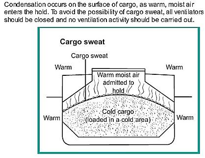
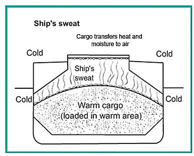
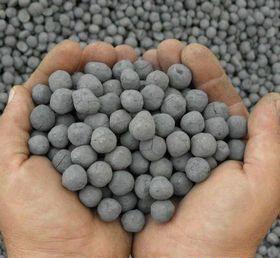


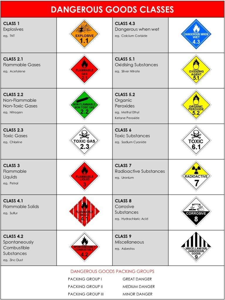
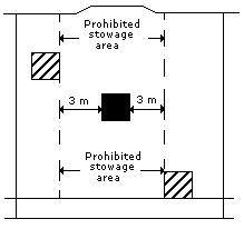
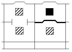
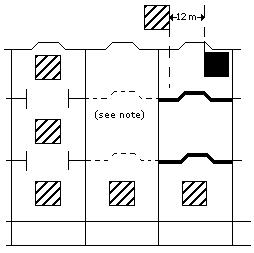
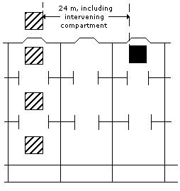


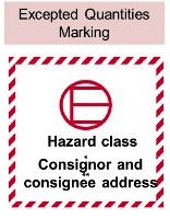


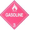


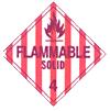


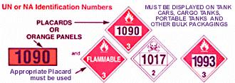 IMDG – Hazardous Materials Warning Placards – UN or NA identification numbers